HIKVISION DS-PDBG8-EG2 Bedienungsanleitung
Quicklinks
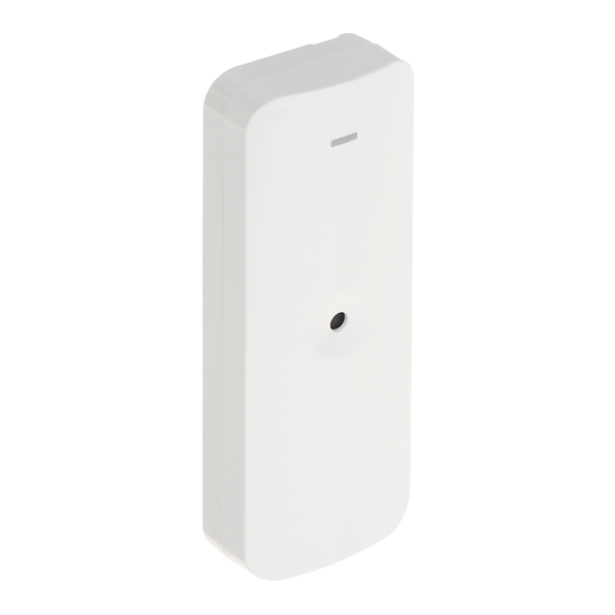
DS-PDBG8-EG2
Wired Glass Break Detector
User Manual
Intrusion Detector - Glass Break Detector
EN 50131-2-7-1:2012+A1+A2
Security Grade 2, Environment Class II
Tested by TÜV Rheinland
English
Appearance
1
1. Front Panel
2. LED Light Pipe
3. PCB
4. Rear Panel
The Printed Circuit Board (PCB)
1. Tamper Resistor Headers
2. Alarm Resistor Headers
3. Sensor
4. Adjustable Resistance (Detection range: 0 to 8 m)
5. Terminal
6. Tamper
7. Alarm LED Latch/Normal
B
B
2s
Latch
Stay On
Normal
8. LED ON/OFF
ON
OFF
R
G
High Frequency Trigger
Low Frequency Trigger
B
R
2s
Alarm
Fault
Resistor Wiring
2
Method 1: Use the jumper to select EOL (End of Line) resistance on
ALARM/TAMPER pins.
Method 2: Add the resistor to ALARM/TAMPER wiring ports.
Note: If EOL wiring is not used, leave the jumpers OFF. Do not force the
jumper if it is not matched the pin. Method 1 & 2 should not be used on the
ALARM/TAMPER at the same time.
a. Alarm Resistance: 1K, 2K2, 4K7, 5K6, 6K8
b. Tamper Resistance: 1K, 2K2, 4K7, 5K6
Connection Type
3
1. Detector
2. Alarm Control Panel
Note: The resistor must be connected in series with one end of the detector.
a. Normally Closed
b. Double End of Line Wiring:
The connection example: Normal: 1K, Alarm: 4.4K, Tamper: Infinite
4
Test
BG (Break Glass) Test
Installation
5
Specification
Sensor
Omnidirectional electret microphone
Power supply
8 to 16 VDC (standard: 12 VDC)
Current consumption
25mA quiescent and maximum at 12V DC
Detection range
8 m (25 ft)
Float, plate, tempered, wired, laminated,
Glass type
double glazing
Glass thickness
2.4 mm to 6.4 mm
Glass size
0.4 m × 0.4 m to 3 m × 3 m
Tamper protection
Front
Blue (alarm), green (flex activation),
LED indicator
red (shatter activation)
Operating temperature
-10°C to 55°C (14°F to 131°F)
Storage temperature
-20°C to 60°C (-4°F to 140°F)
Operating humidity
10% to 90%
Installation
Wall/Ceiling mount
Dimension (H×W×D)
107mm x 38.8mm x 22.5mm
Weight
49.5 g
Warning:
1. Avoid mounting the detector on the same wall as the protected glass
2. Avoid mounting the detector in rooms with noisy equiment(air compressors,
power tools, bells,etc.)
3. Avoid mounting the detectors in humid rooms(bathroom,etc.)
UD21451B-A
1
3
-
0 to 8 m
2
1
1
2
3
4
2
5K6 4K7 2K2 1K
TAMPER
ALARM
1K
-
+
FAULT
TAMPER
ALARM
2K2
EOL
EOL
4K7
5K6
6K8
5K6 4K7 2K2 1K
TAMPER
ALARM
1K
-
+
FAULT
TAMPER
ALARM
2K2
EOL
EOL
4K7
5K6
6K8
3
1
5K6 4K7 2K2 1K
TAMPER
ALARM
-
+
FAULT
TAMPER
ALARM
EOL
EOL
2.2k
2.2k
2.2k
-
+
COM
ZONE3
COM
ZONE2
COM
ZONE1
5
4
B
2 s
Hangzhou Hikvision Digital Technology CO.,Ltd. No.555 Qianmo Road, Binjiang District, Hangzhou 310052, China
+
4
3
8
LED ON
LED OFF
7
Alarm LED Latch
Stay On
6
Alarm LED Normal
5
2s
5K6 4K7 2K2 1K
=
TAMPER
FAULT
TAMPER
ALARM
EOL
EOL
2.2K
5K6 4K7 2K2 1K
TAMPER
=
-
+
FAULT
TAMPER
ALARM
EOL
EOL
2.2K
a
5K6 4K7 2K2 1K
TAMPER
1K
FAULT
TAMPER
ALARM
2K2
EOL
EOL
4K7
5K6
6K8
2.2k
2
COM
ZONE3
COM
ZONE2
COM
2_KA3×25
Français
Apparence
1
38.8 mm
22.5 mm
1. Panneau avant
3. PCB
Circuit imprimé (PCB)
1. Embases de résistance anti-sabotage
3. Capteur
4. Résistance réglable (plage de détection : 0 à 8 m)
5. Borne
6. Anti-sabotage
107.0 mm
Verrou
8. LED ALLUMÉE/ÉTEINTE
Déclencheur haute fréquence
Alarme
Câblage des résistances
2
Méthode 1 : utilisez le cavalier pour sélectionner la résistance d'extrémité de ligne
(EOL) sur les broches ALARME/ANTI-SABOTAGE.
Méthode 2 : ajoutez la résistance aux ports de câblage ALARME/ANTI-SABOTAGE.
Remarque : si vous n'utilisez pas de câblage EOL, les cavaliers doivent rester
désactivés. Ne forcez pas sur le cavalier s'il n'est pas adapté à la broche. Les méthodes
1 et 2 ne doivent pas être utilisées en même temps sur l'ALARME/ANTI-SABOTAGE.
a
ALARM
a. Résistance d'alarme : 1K, 2K2, 4K7, 5K6, 6K8
1K
-
+
b. Résistance anti-sabotage : 1K, 2K2, 4K7, 5K6
2K2
Type de connexion
3
4K7
1. Détecteur
5K6
2. Panneau de contrôle d'alarme
6K8
Remarque : la résistance doit être connectée en série à une des extrémités du détecteur.
a. normalement fermé
b. Câblage d'une double extrémité de ligne :
Exemple de connexion : Normal : 1K, alarme : 4,4K, anti-sabotage : infinie
4
Test
Test de BG (bris de glace)
ALARM
Installation
5
1K
b
2K2
Spécification
4K7
5K6
Capteur
6K8
Alimentation électrique
Consommation de courant
Portée de détection
Type de verre
Épaisseur de verre
b
Dimensions du verre
1
Protection anti-sabotage
Indicateur LED
ALARM
1K
-
+
Température de fonctionnement -10 à 55 °C
2K2
Température de stockage
4K7
Humidité de fonctionnement
5K6
Installation
6K8
Dimensions (L x l x h)
Poids
Deutsch
Aufbau
1
2
1. Frontplatte
Gedruckte Leiterplatte (PCB)
-
+
ZONE1
1. Stiftleisten des Sabotagewiderstands
3. Sensor
4. Einstellbarer Widerstand (Erkennungsbereich: 0 bis 8 m)
5. Anschlussklemmen
Verriegelung
8. LED AN/AUS
Hochfrequenzauslöser
Alarm
Widerstandsverdrahtung
2
Methode 1: Verwenden Sie die Steckbrücke, um Leitungsabschluss-
Widerstand (EOL) an ALARM/SABOTAGE-Kontaktstiften zu wählen.
Methode 2: Schließen Sie den Widerstand an den ALARM/
SABOTAGE-Verdrahtungsanschlüssen an.
Hinweis: Verwenden Sie KEINE Steckbrücken, wenn EOL-Verdrahtung nicht genutzt
wird. Die Steckbrücke darf nicht gewaltsam aufgesteckt werden, wenn sie nicht auf
den Kontaktstift passt. Methode 1 und 2 dürfen nicht gleichzeitig auf den
ALARM/SABOTAGE-Stiftleisten verwendet werden.
a. Alarmwiderstand: 1K, 2K2, 4K7, 5K6, 6K8
b. Sabotage-Widerstand: 1K, 2K2, 4K7, 5K6
2. Conducteur de lumière LED
4. Panneau arrière
2. Embases de résistance d'alarme
7. LED d'alarme : position verrouillée/normale
2 s
S'allume en continu
Normale
MARCHE
ARRÊT
Déclencheur basse fréquence
2 s
Panne
Microphone à électret omnidirectionnel
8 à 16 V CC (standard : 12 V CC)
25 mA au repos et maximale à 12 V CC
8 m
Flotté, plat, trempé, armé, feuilleté et double vitrage
2,4 mm à 6,4 mm
0,4 m × 0,4 m à 3 m × 3 m
Vue de face
Bleu (alarme), vert (activation si choc contre la vitre),
rouge (activation si vitre cassée)
-20 °C à +60 °C
10 à 90 %
Montage mural/au plafond
107 mm x 38,8 mm x 24,5 mm
49,5 g
2. LED-Lichtrohr
3. Leiterplatte
4. Rückwand
2. Stiftleisten des Alarmwiderstands
6. Sabotage
7. Alarm-LED Verriegelung/Normal
2 s
Anwesend Ein
Normal
EIN
AUS
Niederfrequenzauslöser
2 s
Fehler

Verwandte Anleitungen für HIKVISION DS-PDBG8-EG2


Inhaltszusammenfassung für HIKVISION DS-PDBG8-EG2
- Seite 1 Kontaktstift passt. Methode 1 und 2 dürfen nicht gleichzeitig auf den ALARM/SABOTAGE-Stiftleisten verwendet werden. a. Alarmwiderstand: 1K, 2K2, 4K7, 5K6, 6K8 2_KA3×25 b. Sabotage-Widerstand: 1K, 2K2, 4K7, 5K6 UD21451B-A Hangzhou Hikvision Digital Technology CO.,Ltd. No.555 Qianmo Road, Binjiang District, Hangzhou 310052, China...
- Seite 2 Anschlussart Tipo de conexão Italiano Čeština 1. Melder 1. Detector Aspetto Vzhled 2. Alarmzentrale 2. Painel de controle de alarme Hinweis: Der Widerstand muss mit einem Kontakt des Melders in Reihe geschaltet werden. 1. Pannello anteriore 2. Illuminazione tubolare a LED Observação: o resistor deve ser conectado em série com uma extremidade do detector.
- Seite 3 Test Forbindelsestype Polski Türkçe Testul BG (spargere sticlă) 1. Detektor Element Görünüm 2. Alarmkontrolpanel Instalarea 1. Panel przedni 2. Światłowód wskaźnika Bemærk: Modstanden skal serieforbindes med detektorens ene ende. 1. Ön Panel 2. LED Işıklı Boru 3. PCB 4. Arka Panel 3.
- Seite 4 O Manual inclui instruções para utilizar e gerir o produto. As fotografias, os gráficos, as imagens e todas as outras informações doravante apresentadas destinam-se apenas a fins de descritivos e descriptivos y aclaratorios. La información incluida en el manual está sujeta a cambios, sin aviso previo, debido a las actualizaciones de software u otros motivos. Visite el sitio web de Hikvision informazioni contenute nel Manuale sono soggette a modifiche senza preavviso in seguito ad aggiornamenti del firmware o per altri motivi.