Inhaltsverzeichnis
Werbung
Verfügbare Sprachen
Verfügbare Sprachen
Quicklinks
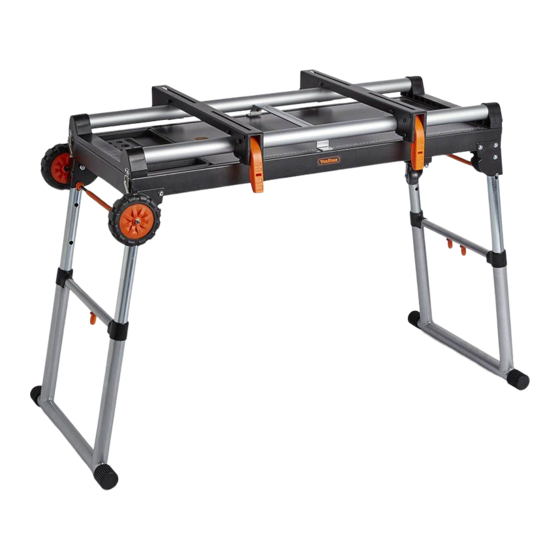
4 IN 1
WORKSTATION
3500102 - Instruction Manual
USE PRECAUTION
INSTRUCTION
For your safety
MANUAL
Read and understand
RISK OF INJURY
EYE PROTECTION
PROTECTIVE GLOVES
Keep hands at a
Must be worn
Must be worn when
safe distance
handling tool
SAFETY INFORMATION
IMPORTANT SAFETY INFORMATION
Safe operation of this accessory requires that you read and understand this manual
carefully before use.
This appliance is not intended for use by persons (including children) with reduced
physical, sensory or mental capabilities, or lack of experience and knowledge, unless
they have been given supervision or instruction concerning use of the appliance by a
person responsible for their safety.
Keep children away from this appliance.
Know your accessory. Read the operator's manual carefully. Learn its applications and
limitations, as well as the specific potential hazards related to this accessory.
If any parts are missing, do not use the stand until the missing parts are replaced.
NOTE This stand is designed for use with mitre saws and slide mitre saws with
mounting dimension not larger than 530mm.
NOTE Maximum weight of the mitre saw and workpiece together must not exceed
150 kg.
Do not modify or use this stand for any purpose for which it is not intended.
Always ensure the mitre saw used is mounted securely and is stable before plugging
in the mitre saw.
This stand is designed to be used on a flat, stable surface. Do not use the product on
an uneven or unstable surface. Be sure to allow enough room to handle and properly
support the workpiece.
Follow the tool mounting instructions carefully, and ensure the tool is fastened
securely.
To reduce the risk of injury from the mitre saw moving or falling off the stand, always
check that all mounting bolts and nuts are securely tightened before moving the
stand or using the tool.
Do not lift any part of the mitre saw that is attached to the stand.
When servicing, use only identical replacement parts. Use of any other parts may
create a hazard or cause product damage.
Save these instructions. Refer to them frequently and use them to instruct others who
may use this accessory.
ALWAYS KEEP WORK AREA CLEAN Cluttered areas and benches invite accidents.
Make sure the floor is clean and not slippery due to wax or sawdust build-up.
CAUTION The assembly pack contains small parts which can pose a choking hazard
to children and pets.
EN
Werbung
Inhaltsverzeichnis

Verwandte Anleitungen für VonHaus 3500102

Inhaltszusammenfassung für VonHaus 3500102
- Seite 1 4 IN 1 SAFETY INFORMATION WORKSTATION IMPORTANT SAFETY INFORMATION 3500102 - Instruction Manual Safe operation of this accessory requires that you read and understand this manual carefully before use. This appliance is not intended for use by persons (including children) with reduced...
- Seite 2 COMPONENTS Ensure All components are present. If any components are missing, do not proceed with assembly. Contact DOMU Brands customer services at hello@domu.co.uk Part Description Stand Handle M6 Nut M6x35 5” Wheel Ø6 Washer Ø8 Washer M8 Spring Washer M8x16 Tool Mount Screw Swivel Wheel...
- Seite 3 ASSEMBLY WARNING Exercise caution. There is a potential for finger pinch/entrapment. Components required to complete this assembly step. • Lay the stand (A) top surface on the floor • Press the Leg Lock Lever and lift leg until the lever clicks into place •...
- Seite 4 ASSEMBLY • Use the M6 Nut (C) and Ø6 Washer (F) to assemble the 5” Wheel (E) to the axle. Components required to complete this assembly step. Use the M6x35 Bolt (D) and M6 Nut (C) to • assemble the Handle (B).
- Seite 5 ASSEMBLY • Insert the Top Tube (M) into the Plastic Base (O) and fix with the Screws (K) Components required to complete this assembly step. • Attach the Central Support (N) to the Top Tube (M) with the Screws (K)
- Seite 6 ASSEMBLY • Put the assembled work top onto the stand and fix it by the 4 lock catches.
- Seite 7 ASSEMBLY SETTING THE HEIGHT • Clench the button inside and pull the bench up and down to adjust to the desired height. • Ensure the locking pin locks securely at the new height.
- Seite 8 MOUNTING A MITRE SAW TO THE STAND Components required to complete this assembly step (not supplied) • Unplug the saw and the saw arm in the downwards position. • Place a tool mount underneath the saw, aligning the mounting holes on the mitre saw base with the slot in the top of the tool mount.
- Seite 9 MOUNTING A MITRE SAW TO THE STAND • Use the Handles located at the rear of the tool mounts to aid in installing or removing saw and bracket assembly • Lift the saw and tool mount assembly, allowing the assembly to tilt slightly toward your body •...
- Seite 10 UNMOUNTING A MITRE SAW FROM THE STAND Raise the Locking Levers (J) to unlock the saw and the tool mounts • • Grasp the handles on either side of the assembly and lift away from the rear rail of the stand to disengage •...
- Seite 11 ASSEMBLY...
- Seite 12 FOLDING THE STAND • Press the Locking Lever until the legs are fully folded...
-
Seite 13: Cleaning & Maintenance
Any unauthorised use may violate worldwide copyright, trademark, and other laws. THANK YOU Thank you for purchasing the 5 in 1 Workstation VonHaus is a registered trademark of DOMU Brands Ltd Made in China for DOMU Brands Ltd M24 2RW. -
Seite 14: Consignes De Sécurité
CONSIGNES DE SÉCURITÉ TRAVAIL 4 EN 1 CONSIGNES IMPORTANTES DE SÉCURITÉ 3500102 - Mode d’emploi Pour manier cet accessoire en toute sécurité, vous devez lire attentivement et comprendre ce manuel avant utilisation. Cet appareil n’a pas été conçu pour être utilisé par des personnes (dont les enfants) souffrant de capacités physiques, sensorielles ou mentales réduites, non plus que par celles qui manquent... - Seite 15 PIÈCES Vérifiez que toutes les pièces sont présentes. S’il manque des pièces, ne commencez pas l’assemblage. Contactez le service à la clientèle de DOMU Brands à hello@domu.co.uk Pièce Description Qté Support x1 Poignée x 1 Écrou M6 x 4 M6x35 x 2 Roulette 5 x 2 Rondelle 6 x 2 Rondelle 8 x 8...
- Seite 16 ASSEMBLAGE ATTENTION Faites preuve de prudence. Vous pourriez vous pincer/coincer les doigts. Pièces nécessaires pour réaliser cette étape d’assemblage. • Couchez la surface supérieure du support (A) sur le sol • Appuyez sur le Levier de Verrouillage du Pied et lever le pied jusqu’à ce que le levier s’enclenche avec un clic •...
- Seite 17 ASSEMBLAGE • Utilisez les Écrous 6 (C) 6 Rondelles (F) pour assembler la Roue 5 (E) sur l’axe. Pièces nécessaires pour réaliser cette étape d’assemblage. • Utilisez les Boulons M6x35 (D) et les Écrous M6 (C) pour monter la Poignée (B).
- Seite 18 ASSEMBLAGE • Insérez le Tube Supérieur (M) dans la Base en plastique (O) puis fixez avec les Vis (K) Pièces nécessaires pour réaliser cette étape d’assemblage. • Attachez le Support central (N) au Tube supérieur (M) avec les Vis (K)
- Seite 19 ASSEMBLAGE • Placez la surface de travail assemblée sur le support et fixez-la avec les 4 loquets de verrouillage.
- Seite 20 ASSEMBLAGE RÉGLAGE DE LA HAUTEUR • Serrez le bouton se trouvant à l’intérieur et tirez l’établi vers le haut et le bas pour le placer à la hauteur souhaitée. • Vérifiez que la cheville de verrouillage est bien bloquée à la nouvelle hauteur.
- Seite 21 MONTER UNE SCIE À ONGLET SUR LE SUPPORT Pièces nécessaires pour réaliser cette étape d’assemblage (non fournies) • Débranchez la scie et avec le bras de scie tourné vers le bas. • Placez un fixe-outil sous la scie, en alignant les trous de fixation sur la base de la scie à...
- Seite 22 MONTER UNE SCIE À ONGLET SUR LE SUPPORT • Utilisez les Poignées situées à l’arrière du fixe-outil pour vous aider à installer et à retirer l’assemblage de la scie et du support • Soulevez l’assemblage de la scie et du fixe-outil en laissant l’assemblage s’incliner légèrement en direction de votre corps •...
- Seite 23 DÉMONTER UNE SCIE À ONGLET SUR LE SUPPORT • Levez les Leviers de verrouillage (J) pour débloquer la scie et les fie-outils • Attrapez les poignées de chaque côté de l’assemblage et soulevez du rail arrière du support pour désengager. •...
- Seite 24 ASSEMBLAGE...
- Seite 25 PLIER LE SUPPORT • Appuyez sur le Levier de verrouillage jusqu’à ce que les pieds soient totalement pliés...
-
Seite 26: Nettoyage Et Entretien
Toute utilisation non autorisée pourrait enfreindre les lois mondiales de droit d’auteur, de marque déposée ainsi que d’autres lois. MERCI Merci d’avoir acheté la Station de travail 5 en 1 VonHaus est une marque déposée de DOMU Brands Ltd Fabriqué en Chine pour DOMU Brands Ltd M24 2RW... -
Seite 27: Sicherheitsinformation
4 IN 1 SICHERHEITSINFORMATION ARBEITS-STATION WICHTIGE SICHERHEITSHINWEISE 3500102 - Bedienungsanleitung Die sichere Bedienung dieses Zubehörs erfordert, dass Sie dieses Handbuch vor dem Gebrauch sorgfältig gelesen und verstanden haben. Dieses Gerät ist nicht für den Gebrauch durch Personen (einschließlich Kinder) mit eingeschränkten physischen, sensorischen oder geistigen Fähigkeiten oder mangelnden... - Seite 28 KOMPONENTEN Stellen Sie sicher, dass alle Komponenten vorhanden sind. Wenn Komponenten fehlen, fahren Sie nicht mit der Montage fort. Kontaktieren Sie DOMU Brands Kundenservice unter hello@domu.co.uk Teil Beschreibung Menge Stand x1 Griff M6 Mutter M6x35 Bolzen 5 Rad x2 6 Unterlegscheibe 8 Unterlegscheibe M8 Federscheibe M8 x 16...
- Seite 29 ZUSAMMENBAU WARNUNG Vorsicht! Es besteht die Gefahr, dass Finger eingeklemmt werden. Komponenten, die für den Abschluss dieses Montageschritts erforderlich sind. • Legen Sie die Standfläche (A) auf den Boden • Drücken Sie auf den Beinverriegelungshebel und heben Sie das Bein an, bis der Hebel einrastet •...
- Seite 30 ZUSAMMENBAU • Verwenden Sie die M6-Mutter (C) und die 6-Unterlegsscheibe (F), um das 5-Rad (E) an der Komponenten, die für den Abschluss dieses Montageschritts erforderlich sind. Achse zu montieren. • Verwenden Sie den M6x35 Bolzen (D) und die M6 Mutter (C), um den Griff (B) zusammenzubauen.
- Seite 31 ZUSAMMENBAU • Das obere Rohr (M) in die Kunststoffbasis (O) einsetzen und mit den Schrauben (K) befestigen Komponenten, die für den Abschluss dieses Montageschritts erforderlich sind. • Befestigen Sie die zentrale Stütze (N) mit den Schrauben (K) am oberen Rohr (M)
- Seite 32 ZUSAMMENBAU • Legen Sie die bestückte Arbeitsplatte auf den Ständer und fixieren Sie sie mit den 4 Schlossverschlüssen.
-
Seite 33: Zusammenbau Einstellen Der Höhe
ZUSAMMENBAU EINSTELLEN DER HÖHE • Drücken Sie den Knopf nach innen und ziehen Sie die Bank auf und ab, um sie auf die gewünschte Höhe einzustellen. • Stellen Sie sicher, dass der Verriegelungsstift sicher in der neuen Höhe einrastet. -
Seite 34: Montage Der Gehrungssägen Auf Dem Stand
MONTAGE DER GEHRUNGSSÄGEN AUF DEM STAND Komponenten, die zur Durchführung dieses Montageschritts erforderlich sind (nicht im Lieferumfang enthalten) • Trennen Sie die Säge und den Sägearm in der unteren Position. • Platzieren Sie eine Werkzeughalterung unter der Säge und richten Sie die Montagelöcher auf der Gehrungssägenbasis mit dem Schlitz an der Oberseite der Werkzeughalterung aus. - Seite 35 MONTAGE DER GEHRUNGSSÄGEN AUF DEM STAND • Verwenden Sie die Griffe an der Rückseite der Werkzeughalterungen, um das Installieren oder Entfernen der Säge- und Halterungsbaugruppe zu erleichtern • Heben Sie die Säge und die Werkzeughalterung an, so dass sich die Einheit leicht zu Ihrem Körper neigen kann •...
-
Seite 36: Abmontierung Der Gehrungssägen
ABMONTIERUNG DER GEHRUNGSSÄGEN • Heben Sie die Werkzeughalterung (J) an, um die Säge und die Werkzeugaufnahmen zu entriegeln • Fassen Sie die Griffe an beiden Seiten der Baugruppe und heben Sie sie von der hinteren Schiene des Ständers ab, um sie zu lösen •... - Seite 37 ZUSAMMENBAU...
- Seite 38 FALTEN DES STÄNDERS • Drücken Sie den Verriegelungshebel, bis die Beine vollständig gefaltet sind...
-
Seite 39: Reinigung/Wartung
Jede nicht autorisierte Nutzung kann weltweite Urheberrechte, Markenrechte und andere Gesetze verletzen. VIELEN DANK Vielen Dank für den Kauf der 5 in 1 Workstation VonHaus ist ein eingetragenes Warenzeichen von DOMU Brands Ltd Made in China für DOMU Brands Ltd. M24 2RW. - Seite 40 INFORMACION DE SEGURIDAD TRABAJO 4 EN 1 INFORMACION DE SEGURIDAD IMPORTANTE 3500102 - Manual de Instrucciones La operación segura de este accesorio requiere que lea y comprenda este manual cuidadosamente antes de usarlo. Este aparato no debe ser utilizado por personas (incluidos niños) con capacidades físicas,...
- Seite 41 COMPONENTES Asegúrese de que todos los componentes estén presentes. Si falta algún componente, no proceda con el ensamblaje. Póngase en contacto con los servicios al cliente de DOMU Brands en hello@domu.co.uk Parte Descripción Cant. Soporte Mango M6 Tuerca M6x35 5 Rueda 6 Arandela 8 Arandela M8 Arandela de Resorte x8...
-
Seite 42: Montaje
MONTAJE ADVERTENCIA Ten cuidado. Existe la posibilidad de atraparse los dedos. Componentes necesarios para completar este paso de montaje. • Coloque la superficie superior del soporte (A) en el piso • Presione la palanca de bloqueo de pierna y levante la pierna hasta que la palanca haga clic en su lugar •... - Seite 43 MONTAJE • Use la M6 Tuerca (C) and 6 Arandela (F) para ensamblar la 5 Rueda (E) al eje. Componentes necesarios para completar este paso de montaje. • Use el M6x35 Tornillo (D) y M6 Tuerca (C) para ensamblar el Mango (B).
- Seite 44 MONTAJE • Inserte el Tubo Tope (M) en la Base de Plástico (O) y ajustelo con los Tornillos (K) Componentes necesarios para completar este paso de montaje. • Adjunte el Soporte Central (N) al Tubo Tope (M) con los Tornillos (K)
- Seite 45 MONTAJE • Coloque la parte superior de trabajo ensamblada en el soporte y arréglela con las 4 capturas de bloqueo.
- Seite 46 MONTAJE AJUSTE DE ALTURA • Apriete el botón dentro y tire del banco hacia arriba y hacia abajo para ajustarlo a la altura deseada. • Asegúrese de que el pasador de bloqueo se traba de forma segura a la nueva altura.
- Seite 47 MONTAJE DE UNA SIERRA INGLETEADORA EN EL SOPORTE Componentes necesarios para completar este paso de montaje (no suministrados) • Desenchufe la sierra y el brazo de la sierra en la posición hacia abajo. • Coloque un soporte de herramienta debajo de la sierra, alineando los orificios de montaje en la base de la sierra ingletadora con la ranura en la parte superior del soporte de la herramienta.
- Seite 48 MONTAJE DE UNA SIERRA INGLETEADORA EN EL SOPORTE • Use las manijas ubicadas en la parte posterior de la herramienta para ayudar a instalar o quitar el conjunto de la sierra y el soporte. • Levante la sierra y el conjunto de montaje de la herramienta, permitiendo que el conjunto se incline ligeramente hacia su cuerpo.
- Seite 49 DESMONTAJE DE UNA SIERRA INGLETEADORA EN EL SOPORTE • Levante las Palancas de bloqueo (J) para desbloquear la sierra y la herramienta de montaje • Sujete las manijas a cada lado del conjunto y levántelo del riel trasero del soporte para desengancharlo •...
- Seite 50 MONTAJE...
- Seite 51 PLEGADO DEL SOPORTE • Presione la palanca de bloqueo hasta que las patas estén completamente dobladas...
-
Seite 52: Limpieza Y Mantenimiento
Cualquier uso no autorizado puede violar los derechos de autor, marcas comerciales y otras leyes en todo el mundo. GRACIAS Gracias por comprar la estación de trabajo 5 en 1 VonHaus es una marca registrada de DOMU Brands Ltd Hecha en China para DOMU Brands Ltd M24 2RW. -
Seite 53: Informazioni Di Sicurezza
INFORMAZIONI DI SICUREZZA LAVORO 4 IN 1 INFORMAZIONI IMPORTANTI SULLA SICUREZZA 3500102 - Manuale di istruzioni Per utilizzare questo accessorio in modo sicuro, leggere e comprendere il presente manuale prima dell’uso. Questo prodotto non è destinato all’utilizzo da parte di soggetti (bambini inclusi) con ridotte capacità... - Seite 54 COMPONENTI Accertarsi della presenza di tutti i componenti. Nel caso in cui un qualsiasi componente dovesse mancare, non procedere con il montaggio. Contattare l’assistenza clienti di DOMU Brands su hello@domu.co.uk Parte Descrizione Q.tà Supporto Manico Dado M6 M6x35 Ruota da 5” Rondella da 6Ø...
- Seite 55 MONTAGGIO ATTENZIONE Prestare attenzione. Pericolo di pizzicamento/intrappolamento delle dita. Componenti richiesti per completare questo step del montaggio. • Appoggiare la superficie superiore del supporto (A) sul pavimento • Premere la Leva di blocco della gamba e sollevare la gamba fino all’inserimento completo della leva.
- Seite 56 MONTAGGIO • Usare il Dado M6 (C) e la Rondella da 6 Ø (F) per montare la Ruota da 5” (E) all’asse. Componenti richiesti per completare questo step del montaggio. • Usare il Bullone M6x35 (D) e il Dado M6 (C) per montare il Manico (B).
- Seite 57 MONTAGGIO • Inserire il Tubo superiore (M) nella Base di plastica (O) e fissare con le Viti (K) Componenti richiesti per completare questo step del montaggio. • Agganciare il Supporto centrale (N) al Tubo superiore (M) con le Viti (K)
- Seite 58 MONTAGGIO • Mettere il piano di lavoro assemblato sul supporto e fissarlo con i 4 blocchi.
- Seite 59 MONTAGGIO IMPOSTAZIONE DELL’ALTEZZA • Stringere il pulsante all’interno e tirare il piano su e giù per regolare all’altezza desiderata. • Accertarsi che i perni di blocco si blocchino in modo sicuro alla nuova altezza.
- Seite 60 MONTAGGIO DI UNA TRONCATRICE SUL SUPPORTO Componenti richiesti per completare questo step del montaggio. • Scollegare l’attrezzo e il braccio dalla posizione verso il basso. • Posizionare l’attacco utensile al di sotto della troncatrice, allineando i fori alla base della troncatrice con le fessure nella parte superiore dell’attacco.
- Seite 61 MONTAGGIO DI UNA TRONCATRICE AL SUPPORTO • Usare i manici posti sul retro degli attacchi per aiutarsi nell’installazione o rimozione della sega e della staffa. • Sollevare la sega e l’attacco, facendolo inclinare delicatamente verso di te. • Agganciare il bordo frontale all’attacco nel binario frontale del supporto.
- Seite 62 SMONTAGGIO DI UNA TRONCATRICE DAL SUPPORTO • Sollevare le Leve di blocco (J) per sbloccare la sega e gli attacchi • Afferrare i manici su entrambi i lati e sollevare dal binario posteriore del supporto per sganciarli. • Con la struttura inclinata leggermente verso di te, solleva la parte anteriore per sganciare dal binario anteriore.
- Seite 63 MONTAGGIO...
- Seite 64 RIPIEGAMENTO DEL SUPPORTO • Premere la Leva di blocco fino a piegare completamente le gambe...
-
Seite 65: Pulizia E Manutenzione
Qualsiasi uso non autorizzato potrebbe violare il copyright a livello mondiale, marchio ed altre leggi. GRAZIE Grazie per aver acquistato la Postazione di lavoro 5 in 1. VonHaus è un marchio registrato di DOMU Brands Ltd Made in Cina per DOMU Brands Ltd M24 2RW...