Seagate Elite 9 Handbuch
Inhaltsverzeichnis
Quicklinks
○
○
○
○
○
○
○
○
○
○
○
Elite 9 Disc Drive
○
○
○
○
○
○
○
○
○
○
○
ST410800N/ND
○
○
○
○
○
○
○
○
○
○
○
ST410800W/WD
○
○
○
○
○
○
○
○
○
○
○
○
○
○
○
○
○
○
○
○
○
○
Installation Guide
○
○
○
○
○
○
○
○
○
○
○
○
○
○
○
○
○
○
○
○
○
○
○
○
○
○
○
○
○
○
○
○
○
○
○
○
○
○
○
○
○
○
○
○
○
○
○
○
○
○
○
○
○
○
○
○
○
○
○
○
○
○
○
○
○
○
○
○
○
○
○
○
○
○
○
○
○
○
○
○
○
○
○
○
○
○
○
○
○
○
○
○
○
○
○
○
○
○
○
○
○
○
○
○
○
○
○
○
○
○
○
○
○
○
○
○
○
○
○
○
○
○
○
○
○
○
○
○
○
○
○
○
○
○
○
○
○
○
○
○
○
○
○
○
○
○
○
○
○
○
○
○
○
○
○
Inhaltsverzeichnis

Verwandte Anleitungen für Seagate Elite 9


Inhaltszusammenfassung für Seagate Elite 9
- Seite 1 ○ ○ ○ ○ ○ ○ ○ ○ ○ ○ ○ ○ ○ ○ ○ ○ ○ ○ Elite 9 Disc Drive ○ ○ ○ ○ ○ ○ ○ ○ ○ ○ ○ ○ ○ ○ ○ ○ ○ ○...
-
Seite 2: Inhaltsverzeichnis
General description ..........12 Initial setup information ........... 18 Kühlung des Systems .......... 29 Installation des Laufwerkes und Anschluß der Kabel ........32 © 1994 Seagate Technology, Inc. All rights reserved Publication Number: 83328850, Rev. B October 1994 Seagate ®... -
Seite 3: Preface
Elite™ 9 SCSI disc drives. It provides support services, performance specifications, and initial setup informa- tion. Additional information is available in the Elite 9 Product Manual (part number 83328860). Contact your Seagate sales representative if you need to order this publication. -
Seite 4: Important Safety Information And Precautions
• Ground yourself to the drive whenever the drive elec- tronics are or will be exposed. Connect yourself to ground with a wrist strap (Seagate part number 12263496). Connection may be made to any grounded metal assembly. As a general rule, remember that you and the drive electronics must all be grounded to avoid potentially damaging static discharges. - Seite 5 Elite 9 Installation Guide, Rev. B read and followed to minimize or eliminate the risk of personal injury. The warnings point out conditions or practices that may endanger you or others. The cautions point out conditions or practices that may damage the unit, possibly making it unsafe for use.
- Seite 6 As a component, this drive is designed to be installed and operated in accordance with UL1950, IEC950, EN60950, CSA C22.2 950, and VDE0805. Seagate takes all reasonable steps to ensure that its products are certifiable to currently accepted stan-...
-
Seite 7: Wichtige Sicherheitshinweise
This unit is a component part and as such is not meant to comply with FCC or similar national requirements as a stand-alone unit. Engineering radiated emissions test results are available through the Seagate Safety Depart- ment to assist the subsystem designer. Wichtige Sicherheitshinweise Vorsicht. - Seite 8 Elite 9 Installation Guide, Rev. B dürfen nur von qualifiziertem Fachpersonal vorgenommen werden. Wir empfehlen die Verfahren in diesem Handbuch als effektive Methoden zur Wartung und Reparatur der Einheit. Einige Verfahren erfordern Spezialwerkzeuge; diese müssen zur sachgemäßen Ausführung der Wartungsarbeiten und aus Sicherheitsgründen den Empfehlungen...
- Seite 9 Elite 9 Installation Guide, Rev. B zuerst sicher, daß das gewählte Verfahren weder Ihre persönliche Sicherheit noch die Leistung der Einheit gefährdet. Beachten Sie in jedem Fall die folgenden Warn-und Vorsichtshinweise: • Führen Sie alle Wartungsarbeiten entsprechend den Anweisungen in diesem Handbuch aus.
- Seite 10 Elite 9 Installation Guide, Rev. B • Befolgen Sie die oben unter “Electrostatic Discharge Protection” angegebenen Sicherheitsmaßnahmen. • Nehmen Sie keine Platinen aus dem Laufwerkgehäuse. Wenn eine Platine defekt ist, muß das gesamte Laufwerk zur Reparatur eingeschickt werden. Die Herausnahme von Platinen durch andere Personen als die für die werkseitige Reparatur zuständigen kann...
- Seite 11 Elite 9 Installation Guide, Rev. B geltenden Standards zu gewährleisten. Zu den typischen Anwendungen dieser Festplattenwerke zählen Systemeinbau durch den Kunden und die Konstruktion von Untersystemen. Sicherheitsbehörden gewähren eine bedingte Zulassung für Komponenten wie das Elite- Festplattenlaufwerk vorbehaltlich der endgültigen Zulassung im Endprodukt.
-
Seite 12: Technical Support Services
Please contact your dealer for technical support and installation troubleshooting. Product technical support is available for all Seagate products by calling the SeaFAX™, SeaFONE™, SeaTDD™, or SeaBOARD™ services. These are toll calls if you dial from outside of the number’s local dialing area. - Seite 13 Elite 9 Installation Guide, Rev. B access this service, which is available from 8:00 . to 5:00 . PST, Monday through Friday. SeaBOARD: The Seagate Technical Support Bulletin Board System (BBS) is available 24 hours a day, 7 days a week. A modem is required to access this service.
-
Seite 14: General Description
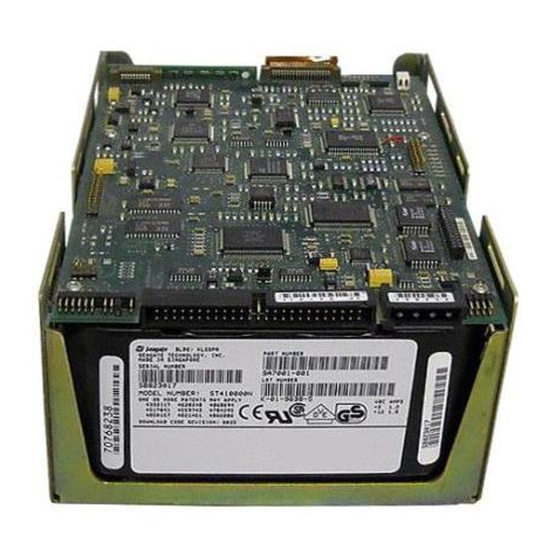
Elite 9 Installation Guide, Rev. B General description Elite 9 SCSI disc drives are high capacity, random- access digital-data storage devices. An Elite 9 drive is illustrated in Figure 1. Specifications and DC power requirements for the drive are listed in a table following the figure. - Seite 15 Elite 9 Installation Guide, Rev. B SCSI I/O Connector DC Power Connector Figure 1. Elite 9 family disc drive (ST410800N shown)
- Seite 16 Elite 9 Installation Guide, Rev. B Characteristics of ST410800 drives N/ND W/WD SCSI-2 Interface Fast Fast & Wide Multi-segmented cache Physical 1,024 Kbytes 1,024 Kbytes Available to user 960 Kbytes 960 Kbytes Capacity Unformatted 10,800 Mbytes 10,800 Mbytes Formatted 9,090 Mbytes 9,090 Mbytes...
- Seite 17 Elite 9 Installation Guide, Rev. B DC power requirements for ST410800N/ND drives Single-ended Differential + + + + + 5V + + + + + 12V + + + + + 5V + + + + + 12V ± ± ± ± ± 5% ±...
- Seite 18 Elite 9 Installation Guide, Rev. B DC power requirements for ST410800W/WD drives Single ended Differential [11] [11] ± ± ± ± ± 5% ± ± ± ± ± 5% ± ± ± ± ± 5% ± ± ± ± ± 5%...
- Seite 19 See the +12V current profile in the Elite 9 Product Manual . This condition occurs when the Motor Start option is en- abled and the drive has not yet received a start motor command.
-
Seite 20: Initial Setup Information
Elite 9 Installation Guide, Rev. B continued from previous page All power-saving features are enabled. Seeking is defined as a third-stroke seek at OD. A com- mand is issued every 23 msec. Read track is defined as repeat reads of track 15 with an 88% duty cycle. - Seite 21 Elite 9 Installation Guide, Rev. B Setting the SCSI ID jumpers Each device on the SCSI chain must have a unique SCSI ID. The host system’s SCSI controller usually uses the highest-numbered ID available (ID7 in non-wide sys- tems); therefore the lower-numbered SCSI IDs are nor- mally used for the other SCSI devices such as this Elite disc drive.
- Seite 22 Elite 9 Installation Guide, Rev. B SCSI I/O Connector DC Power Connector Pin 1 SCSI ID = 0 (factory setting) SCSI ID = 1 SCSI ID = 2 SCSI ID = 3 SCSI ID = 4 SCSI ID = 5...
- Seite 23 Elite 9 Installation Guide, Rev. B Terminating the drive If you are installing the drive in a system that has other SCSI devices installed, terminate only the end devices on the SCSI chain. A SCSI “device” is any disc drive, scanner, tape backup unit, or other piece of hardware connected to your system using the SCSI bus.
- Seite 24 Elite 9 Installation Guide, Rev. B To terminate ST410800N and ST410800W drives, en- able the permanently mounted IC terminators by install- ing a jumper on J4A pins 19 and 20 as shown in Figure 4. If you install one of these models and it is not on the end...
- Seite 25 Elite 9 Installation Guide, Rev. B ST410800ND and ST410800WD (differential) drives are shipped with terminators (part number 15479501) in- stalled on the circuit board. Figure 5 illustrates the locations of the terminators. To remove termination from the drive, carefully lift the terminators from their sockets.
- Seite 26 Figure 6. Setting terminator power jumpers (ST410800N shown) Changing other applicable jumper options Elite 9 drives are designed for use in a variety of systems. Some installations may require you to change one or more of the other jumpers to meet specific system requirements;...
- Seite 27 Elite 9 Installation Guide, Rev. B SCSI I/O Connector DC Power Connector Pin 1 Write Protect Write Enable (factory setting) Reserved LED Connections Connect the anode to the desired LED connector and the cathode to the ground pin. Active LED connector (+)
- Seite 28 Elite 9 Installation Guide, Rev. B Synchronizing spindles in multiple drive configurations If you are installing two or more Elite 9 drives, you may (optionally) synchronize their spindles to reduce the latency associated with switching from one drive to another.
- Seite 29 Elite 9 Installation Guide, Rev. B Figure 9 illustrates a typical synchronized spindle configuration. After connecting each drive with spindle sync cables, you must designate a master spindle sync reference source. This master source is normally a disc drive located on the same SCSI bus as the other drives you want to synchronize with.
- Seite 30 Elite 9 Installation Guide, Rev. B Providing adequate cooling The enclosure design must ensure adequate cooling for the drive. The maximum ambient temperature is 45 The drive’s product manual (83328860) describes how to evaluate the air-flow design. The evaluation consists...
-
Seite 31: Kühlung Des Systems
Elite 9 Installation Guide, Rev. B Kühlung des Systems Die Gehäusekonstruktion muß eine ausreichende Kühlung des Laufwerkes gewährleisten. Die Umgebungstemperatur darf maximal 45 C betragen. Die Produkthandbuch Elite 9 (Dokument 83328860) enthalten Anweisungen zur Beurteilung der Luftstromkonstruktion. Die Beurteilung muß sicherstellen, daß... - Seite 32 Elite 9 Installation Guide, Rev. B Above unit Über der Einheit Under unit Unter der Einheit Note. Air flows in the direction shown (front to back) or in reverse direction (back to front) Hinweis. Luftstrom in der angezeigten Richtung (von vorne nach hinten) oder in umgekehrter...
- Seite 33 Elite 9 Installation Guide, Rev. B Mounting the drive and connecting cables Do not touch the connector pins or any components on the control board without observing static-discharge precautions. Always handle the drive by the frame only. The drive may be mounted in any orientation (horizon- tally, vertically, and any combination thereof);...
-
Seite 34: Installation Des Laufwerkes Und Anschluß Der Kabel
Elite 9 Installation Guide, Rev. B Installation des Laufwerkes und Anschluß der Kabel Beachten Sie beim Handhaben und Anfassen der A n s c h l u ß s t i f t e u n d K o m p o n e n t e n d i e Vorsichtsmaßnahmen zur Verhinderung statischer... - Seite 35 Elite 9 Installation Guide, Rev. B M4 x .70 Metric Threads (4) 6-32 Threads (4) Side C.G. Bottom 6-32 Threads (4) C.G. The maximum screw depth that ± 3.25 0.01 82.55 extends into chassis must not 0.86 ± 0.01 21.84 exceed 0.14 inches.
- Seite 36 Elite 9 Installation Guide, Rev. B 2. Verify that all connections between the drive and the host system are correctly installed. 2. Prüfen Sie, ob alle Verbindungen zwischen dem Laufwerk und dem Host-System korrekt hergestellt sind. 3. Verify that you have correctly installed SCSI ID jump- ers and that you have properly terminated the SCSI bus (see Figures 2, 3, 4, 5, and 6).
- Seite 37 Elite 9 Installation Guide, Rev. B 4. Schließen Sie das 50-polige SCSI-Kabel an den SCSI-Steckverbinder des Laufwerkes an (wie bereits in Abbildung 1 gezeigt). Das Kabel darf nicht gedehnt oder gedrückt werden und es darf den Luftstrom zur Kühlung des Systems nicht behindern.
- Seite 38 Elite 9 Installation Guide, Rev. B Note. Signal ground on the power control board (PCB) and the head and disc assembly (HDA) are con- nected together in this drive and you cannot separate them. The equipment in which you have...
- Seite 39 2. Boot the system from a system floppy disc or from a previously installed hard disc drive if there is one. 3. Format the disc drive. The Elite 9 disc drive is de- signed to operate with a variety of operating systems.
- Seite 40 Elite 9 Installation Guide, Rev. B Seagate Technology, Inc. 920 Disc Drive, Scotts Valley, CA 95066-4544, USA Publication Number: 83328850, Rev. B, Printed in USA...