Herunterladen Inhalt Inhalt Diese Seite drucken

Werbung

Verfügbare Sprachen
  • DE

Verfügbare Sprachen

  • DEUTSCH, seite 30
MANUALE DI ISTRUZIONI
INSTRUCTION MANUAL • BEDIENUNGSANLEITUNG
MANUEL D'INSTRUCTION • MANUAL DE INSTRUCCIONES
SPIN BIKE
LEI002997NOC

Werbung

Inhaltsverzeichnis
loading

Inhaltszusammenfassung für Kasanova LEI002997NOC

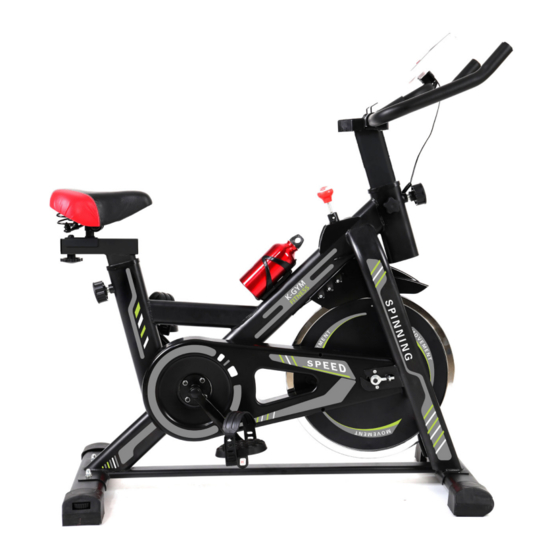
  • Seite 1 MANUALE DI ISTRUZIONI INSTRUCTION MANUAL • BEDIENUNGSANLEITUNG MANUEL D’INSTRUCTION • MANUAL DE INSTRUCCIONES SPIN BIKE LEI002997NOC...
  • Seite 2 SPIN BIKE ATTENZIONE: PESO MASSIMO DELL’UTENTE: 120KG PRIMA DELL’USO, LEGGERE ATTENTAMENTE LE ISTRUZIONI CONTENUTE IN QUESTO MANUALE E CONSERVARLE PER EVENTUALI CONSULTAZIONI FUTURE. INFORMAZIONI SULLA SICUREZZA ATTENZIONE: PRIMA DELL’USO, LEGGERE LE SEGUENTI ISTRUZIONI DI SICUREZZA PER EVITARE IL RISCHIO DI LESIONI GRAVI. IMPORTANTE: QUESTO ATTREZZO É...
  • Seite 3 SPIN BIKE 8. Usare l’attrezzo in conformità a quanto descritto in questo manuale. Se si riscontrano componenti difettosi durante l’assemblaggio dell’attrezzo o se si sente un rumore insolito proveniente dall’attrezzatura durante l’allenamento, interrompere immediatamente l’uso. Non riprendere la sessione di allenamento finché il problema non è...
  • Seite 4: Lista Delle Parti

    SPIN BIKE LISTA DELLE PARTI...
  • Seite 5 SPIN BIKE DIMEN- NOME SPECIFICA Q.TÀ NOME Q.TÀ SIONI Dado di regola- Telaio Montaggio zione Stabilizzatore Bullone a testa Montaggio M8X50 anteriore tonda Stabilizzatore Montaggio Rondella piana Φ8.5 posteriore Reggisella Montaggio Copridado Tubo manubrio Montaggio Rondella piana Φ10.5 Bullone con testa Manubrio Montaggio M8X16...
  • Seite 6: Istruzioni Per Il Montaggio

    SPIN BIKE ISTRUZIONI PER IL MONTAGGIO STEP 1 Piedini di supporto Ruota di trasporto Fissare con la chiave in dotazione (25) lo stabilizzatore anteriore (2) al telaio (1) usando i bulloni a testa tonda (16), le rondelle piane (17) e i copridadi (18), facendo attenzione a stringerli fino in fondo.
  • Seite 7 SPIN BIKE STEP 2 Fissare il pedale destro (12) contraddistinto da una R alla corrispondente pedivella destra situata sul telaio (1) tramite la chiave in dotazione (25). Nota: per fissare il pedale destro, avvitare in senso orario. Allo stesso modo, fissare il pedale sinistro (13) contraddistinto da una L alla corrispondente pedivella sinistra situata sul telaio (1) tramite la chiave in dotazione (25) Nota: per fissare il pedale sinistro, avvitare in senso antiorario.
  • Seite 8 SPIN BIKE STEP 3 Inserire il reggisella (4) nel telaio (1), rilasciando la manopola di regolazione (14) in modo che si inserisca automaticamente nel foro corrispondente del reggisella (4). Allo stesso modo, inserire il tubo manubrio (5) nel telaio (1) e fissarlo con la manopola di regolazione (14) nel foro corrispondente.
  • Seite 9 SPIN BIKE STEP 4 Fissare la slitta sella (7) al reggisella con una rondella piana (19) e un dado di regolazione (15). Montare poi il sellino (8) sulla slitta sella (7), fissandolo e serrandolo a mano. Nota: La possibilità di allentare i dadi di regolazione (15) permette di regolare la posizione della slitta sella (7) prima e dopo averla posizionata, successivamente riavvitare i dadi di regolazione (15).
  • Seite 10 SPIN BIKE STEP 5 Montare il manubrio (6) sul tubo manubrio (5) fissandolo con la rondella piana (17), la rondella elastica (21) e il bullone con testa a cupola (20), serrandoli bene con una chiave a brugola (26).
  • Seite 11 SPIN BIKE STEP 6 Assemblare il supporto computer (10) sul manubrio (6) utilizzando una vite autofilettante (24) e fissarlo con la chiave a brugola (26). Montare quindi il computer (9) sul support computer (10). Inserire il trasmettitore di impulsi (22) nel supporto adeguato sul retro del computer (9). Inserire il cavo di segnale (23) nel supporto sensore sul retro del computer (9).
  • Seite 12 SPIN BIKE STEP 7 Installare il supporto portacellulare (11) sul manubrio (6). ATTENZIONE: prima dell’uso, assicurarsi che tutti i componenti siano ben fissati e che l’attrezzo sia posizionato su una superficie stabile.
  • Seite 13 SPIN BIKE ISTRUZIONI DEL COMPUTER: A, INSTALLAZIONE DELLA BATTERIA Inserire due pile AA da 1.5V nel vano batteria posizionato sul retro del computer (dopo aver inserito le due pile, tutti i valori dovrebbero essere a “0”). B, DESCRIZIONE DELLE FUNZIONI 1, Scansione automatica (SCAN): aprire la schermata o premere il pulsante per selezionare la modalità...
  • Seite 14: Consigli Per L'allenamento

    SPIN BIKE C, ATTENZIONE 1, Se il display elettronico non funzionasse normalmente, provare a reinstallare le pile e controllare che siano inserite con la giusta polarità. 2, Specifiche della batteria: 1 AA 5 1.5V 3, Per eliminare la batteria, rimuoverla dal display elettronico e maneggiarla con attenzione.
  • Seite 15 SPIN BIKE B, Fase di allenamento È la fase di allenamento vera e propria, man mano che ci si allena si noterà una maggiore flessibilità nei muscoli delle gambe. Durante l’allenamento, è fondamentale adattare l’intensità di allenamento alle proprie condizioni fisiche. Prestazione cardiovascolare Esercizi aerobici intermedi Brucia grassi...
  • Seite 16 SPIN BIKE CAUTION: MAX USER WEIGHT: 120KG BEFORE USING THIS EQUIPMENT, CAREFULLY FOLLOW THE INSTRUCTIONS AND READ ALL PRECATION, THEN RETAIN FOR FUTURE REFERENCE. SAFETY INFORMATION WARNING TO REDUCE THE RISK OF SERIOUS INJURY, READ THE FOLLOWING SAFETY INSTRUCTIONS BEFORE USING THE EQUIPMENT. IMPORTANT: THIS UNIT IS INTENDED FOR HOME USE ONLY 1.
  • Seite 17 SPIN BIKE assembling or checking the equipment, or if you hear any unusual noise coming from the equipment during use, stop. Do not use the equipment until the problem has been rectified. 9. Wear suitable clothing whilst using the equipment. Avoid wearing loose clothing which may get caught in the equipment or that may restrict or prevent movement.
  • Seite 18: Parts List

    SPIN BIKE PARTS LIST...
  • Seite 19 SPIN BIKE NAME SPEC. NAME SIZE Main Body Assembly Adjusting Nut Front Stabilizer Assembly Carriage Bolt M8X50 Rear Stabilizer Assembly Flat Washer Φ8.5 Saddle Post Assembly Cover Nut Handle Post Assembly Flat Washer Φ10.5 Handle Frame Assembly Button Head Bolt M8X16 Saddle Adjust- Assembly...
  • Seite 20 SPIN BIKE ASSEMBLY INSTRUCTIONS STEP 1 The Front Stabilizer (2) is fixed on the Main Body (1) with Carriage Bolts (16), Flat washers (17) and Cover nuts (18), and fixed with open Spanner (25). Note: the move wheels of the Front Stabilize(2) are forward,as shown. Similarly, the Rear Stabilizer (3) is fixed on the Main Body (1) with carriage Bolts (16), flat washers (17) and cover nuts (18), and fixed with open Spanner (25).
  • Seite 21 SPIN BIKE STEP 2 Install the Right pedal (12) with R mark on The Main Body (1) and fix it with an open Spanner (25). Note: tighten it clockwise. Similarly, Install the Left pedal (13) with L mark on the Main Body (1) and fixed with an open Spanner (25).
  • Seite 22 SPIN BIKE STEP 3 The Saddle Post (4) is inserted into the Main Body (1), and the Adjusting knob (14) is pulled out so that the Adjusting knob (14) is automatically inserted into the corresponding hole of the Saddle Post (4). Similarly, the Handle Post (5) is inserted into the Main Body (1), and the Adjusting knob (14) is pulled out so that the Adjusting knob (14) is automatically inserted into the corresponding hole of the Handle Post (5).
  • Seite 23 SPIN BIKE STEP 4 The Saddle Adjustment Frame (7) is installed in the Saddle Post (4) and fixed with the Flat washer (19) and an adjusting nut (15). Then the Saddle (8) is arranged on the Saddle Adjustment Frame (7), and is fixed and tightened by Hand Note: Loosening the adjusting nut (15) can adjust the Saddle Adjustment Frame (7) position before and after adjusting to the corresponding position, the adjusting nut (15) needs to be tightened .
  • Seite 24 SPIN BIKE STEP 5 The Handle Frame (6) is fixed on the Handle Post (5) with Flat washers(17), the Spring washers (21) and the Button head bolts (20), and tightened with an inner hexagonal wrench(26).
  • Seite 25 SPIN BIKE STEP 6 The Monitor Holder (10) is pulled and fixed on the Handle Frame (6) with the Self tapping screw (24) and tightened with the inner hexagonal wrench (26). The Monitor (9) is mounted on the Monitor Holder (10). Insert the Pulse Wire(22) into the “pulse”...
  • Seite 26 SPIN BIKE STEP 7 Install the Mobile phone holder (11) on the Handle Frame (6). CAUTION: before using, please reconfirm that each part is tight and firm, and the machine is stable with the ground.
  • Seite 27: Monitor Function

    SPIN BIKE MONITOR FUNCTION A, BATTERY INSTALLATION Load two 1.5V AA battery in the battery box on the back (after each battery replacement, all values will be “0”) B, FUNCTIONAL DESCRIPTION 1, Automatic scanning (SCAN): open the screen or press the button to enter the SCAN state, all the functions of the TIME--SPD--DIST--CAL--ODO--PUL will be automatically displayed on the main screen.
  • Seite 28: Training Instructions

    SPIN BIKE 3, When the battery is scrapped, it must be removed from the electronic watch and handled safely. TRAINING INSTRUCTIONS IN ADDITION TO THE USE OF THE EQUIPMENT CAN ENHANCE PHYSICAL FITNESS AND EXERCISE MUSCLES, BUT ALSO THROUGH A REASONABLE DIET TO PLAY A ROLE IN WEIGHT LOSS.
  • Seite 29 SPIN BIKE B, Training Stage This stage is the formal training phase, after a long period of practice can improve the flexibility of the leg muscles. In the training process, the key is to do the training according to the training condition, and to choose the reasonable training intensity. Note: To keep the heart rate within the corresponding target range for at least 1 minutes of training, most people in the beginning of training lasted 15--20 minutes.
  • Seite 30: Sicherheitshinweise Achtung

    SPIN BIKE ACHTUNG: HÖCHSTGEWICHT DES BENUTZERS: 120KG LESEN SIE VOR DEM GEBRAUCH DIE BEDIENUNGSANLEITUNG SORGFÄLTIG DURCH UND BEWAHREN SIE SIE FÜR SPÄTERE KONSULTATIONEN AUF. SICHERHEITSHINWEISE ACHTUNG LESEN SIE VOR DEM GEBRAUCH DES GERÄTS DIE SICHERHEITSHINWEISE DURCH, UM SCHWERE VERLETZUNGEN ZU VERMEIDEN. WICHTIG: DIESES GERÄT IST AUSSCHLIESSLICH FÜR DEN HEIMGEBRAUCH ENTWORFEN WORDEN 1.
  • Seite 31 SPIN BIKE ungewöhnliche Geräusche beim Trainieren hört, die vom Gerät kommen, den Gebrauch sofort abbrechen. Das Training, solange das Problem nicht gelöst worden ist, nicht wieder aufnehmen. 9. Immer geeignete Kleidung und Sportschuhe beim Trainieren tragen. Keine weite Kleidung tragen, die sich in den beweglichen Teilen des Geräts verfangen oder die Bewegung des Benutzers einschränken kann.
  • Seite 32 SPIN BIKE TEILELISTE...
  • Seite 33 SPIN BIKE SPEZIFIKA- MEN- ABMES- NAME NAME MENGE TION SUNGEN Rahmen Montage Stellmutter Vordere Stütze Montage Schlossschraube M8X50 Flache Unterleg- Hintere Stütze Montage Φ8.5 scheibe Sattelstütze Montage Mutter kappen Flache Unterleg- Lenkerstange Montage Φ10.5 scheibe Rundkopfschrau- Lenker Montage M8X16 Elastische Unter- Sattelschlitten Montage Φ8.5...
  • Seite 34 SPIN BIKE MONTAGEANLEITUNGEN STEP 1 Piedini di supporto Ruota di trasporto Mit dem mitgelieferten Schlüssel (25) die vordere Stütze (2) am Rahmen (1) mit den Schlossschraube (16), den flachen Unterlegscheiben (17) und den Mutter kappen (18) festschrauben, darauf achten, dass alles fest angezogen ist. Hinweis: Die Transporträder der vorderen Stütze (2) müssen vorne, wie in der Abbildung gezeigt, angebracht werden.
  • Seite 35 SPIN BIKE STEP 2 Die rechte Pedale (12), die mit einem R gekennzeichnet ist, an die rechte Tretkurbel am Rahmen (1) mit dem mitgelieferten Schlüssel (25) festschrauben. Hinweis: Die rechte Pedale im Uhrzeigersinn aufschrauben. Auf dieselbe Weise die linke Pedale (13), die mit einem L gekennzeichnet ist, an die linke Tretkurbel am Rahmen (1) mit dem mitgelieferten Schlüssel (25) festschrauben Hinweis: Die linke Pedale gegen den Uhrzeigersinn aufschrauben.
  • Seite 36 SPIN BIKE STEP 3 Die Sattelstütze (4) in den Rahmen (1) einfügen und die Rändelschraube (14) loslassen, damit sie automatisch in das entsprechende Loch in der Sattelstütze (4) gleitet. Auf dieselbe Weise die Lenkerstange (5) in den Rahmen (1) einschieben und mit der Rändelschraube (14) im entsprechenden Loch befestigen.
  • Seite 37 SPIN BIKE STEP 4 Den Sattelschlitten (7) an der Sattelstütze mit einer flachen Unterlegscheiben (19) und einer Stellmutter (15) befestigen. Dann den Fahrradsattel (8) auf dem Sattelschlitten (7) mit der Hand festschrauben. Hinweis: Durch Lösen der Stellmuttern (15) kann man die Position des Sattelschlittens (7) einstellen, bevor und nachdem man ihn aufgesetzt hat, danach die Stellmuttern (15) anziehen.
  • Seite 38 SPIN BIKE STEP 5 Den Lenker (6) auf die Lenkerstange (5) mit der flachen Unterlegscheibe (17), der elastischen Unterlegscheibe (21) und der Rundkopfschraube (20) befestigen, mit dem Inbusschlüssel (26) die Schraube fest anziehen.
  • Seite 39 SPIN BIKE STEP 6 Die Computerhalterung (10) auf dem Lenker (6) mit der selbstschärfenden Schraube (24) festschrauben, mit dem Inbusschlüssel (26) die Schraube fest anziehen. Dann den Computer (9) an die Computerhalterung (10) montieren. Der Impulse Draht (22) in die Halterung hinten am Computer stecken (9). Das Signalkabel (23) in die Sensorhalterung hinten am Computer (9) stecken.
  • Seite 40 SPIN BIKE STEP 7 Die Handyhalterung (11) am Lenker (6) befestigen. ACHTUNG: Vor dem Gebrauch überprüfen, dass alle Teile fest sitzen und dass das Gerät auf einer stabilen Fläche steht.
  • Seite 41: Anleitungen Für Den Computer

    SPIN BIKE ANLEITUNGEN FÜR DEN COMPUTER A, EINSETZEN DER BATTERIE Die beiden Batterien AA 1.5 V in das Batteriefach hinten am Computer einsetzen (nach dem Einsetzen der Batterien müssten alle Werte auf „0“ stehen). B, BESCHREIBUNG DER FUNKTIONEN 1, Automatischer Scan (SCAN): Den Bildschirm öffnen oder die Taste für die Modusauswahl SCAN drücken, auf dem Bildschirm erscheinen alle Funktionen TIME (Zeit) - SPD (Geschwindigkeit) - DIST (Entfernung) - CAL (Kalorien) - ODO (Kilometerzähler) - PUL (Puls).
  • Seite 42: Tipps Für Das Training

    SPIN BIKE C, ACHTUNG 1, Wenn das elektronische Display nicht normal funktioniert, die Batterien herausnehmen und neu einsetzen, dabei genau auf die Pole achten. 2, Batterieangaben: 1 AA 5 1.5V 3, Die Batterie am Ende ihrer Nutzzeit aus dem elektronischen Display nehmen und vorsichtig handhaben.
  • Seite 43: Umweltgerechte Entsorgung

    SPIN BIKE B, Trainingsphase Das ist die richtige Trainingsphase, nach und nach spürt man, wie die Beinmuskeln geschmeidiger werden. Während des Trainings ist es äußerst wichtig, die körperliche Übung seiner körperlichen Form anzupassen, indem man die richtige Trainingsintensität auswählt. Kardiovaskuläre Leistung Aerobic-Zwischenübungen Verbrennt Fette Hinweis:...
  • Seite 44 SPIN BIKE ATTENTION: POIDS MAXIMUM DE L’UTILISATEUR: 120KG AVANT TOUTE UTILISATION, VEUILLEZ LIRE ATTENTIVEMENT LES INSTRUCTIONS CONTENUES DANS CE MANUEL ET LES CONSERVER POUR TOUTE RÉFÉRENCE ULTÉRIEURE CONSIGNES DE SÉCURITÉ ATTENTION AVANT L’UTILISATION, VEUILLEZ LIRE LES CONSIGNES DE SÉCURITÉ SUIVANTES POUR RÉDUIRE LES RISQUES DE BLESSURE GRAVE. IMPORTANT : CE PRODUIT EST DESTINÉ...
  • Seite 45 SPIN BIKE 7. Le niveau de sécurité du vélo spinning ne peut être garanti qu’en cas de contrôle régulier de celui-ci à la recherche d’éventuels dommages ainsi que de traces d’usure. 8. Utilisez toujours l’appareil comme indiqué dans ce manuel. Si vous trouvez des pièces défectueuses lors de l’assemblage ou de l’entretien de l’appareil ou si vous entendez un bruit inhabituel provenant de l’équipement pendant l’utilisation, arrêtez la session d’entraînement.
  • Seite 46: Liste Des Pièces

    SPIN BIKE LISTE DES PIÈCES...
  • Seite 47 SPIN BIKE SPÉCIFICAT- QTÉ TAILLE QTÉ Cadre principal Montage Écrou de serrage Stabilisateur Boulon de Montage M8X50 avant carrosserie Stabilisateur Montage Rondelle plate Φ8.5 arrière Tige de selle Montage Cache-écrou Tige de guidon Montage Rondelle plate Φ10.5 Boulon à tête Guidon Montage M8X16...
  • Seite 48: Notice De Montage

    SPIN BIKE NOTICE DE MONTAGE ÉTAPE 1 Piedini di supporto Ruota di trasporto Fixez le stabilisateur avant (2) sur le cadre principal (1) avec les boulons de carrosserie (16), les rondelles plates (17) et les cache-écrous (18) et serrez-les bien à l’aide de la clé...
  • Seite 49 SPIN BIKE ÉTAPE 2 Fixez la pédale droite (12) marquée par la lettre R sur la manivelle droite correspondante placée sur le cadre principal (1) et vissez-la à l’aide de la clé à fourches fournie (25). Note : pour fixer la pédale droite, tournez-la dans le sens des aiguilles d’une montre. Procédez de même avec l’autre pédale : fixez la pédale gauche (13) marquée par la lettre L sur la manivelle gauche correspondante placée sur le cadre principal (1) et vissez-la à...
  • Seite 50 SPIN BIKE ÉTAPE 3 Fixez la tige de selle (4) sur le cadre principal (1), le bouton de réglage (14) est tiré de sorte qu’il s’insère automatiquement dans le trou correspondant de la tige de selle (4). De même, insérez la tige de guidon (5) dans le cadre principal (1) et fixez-la sur le trou correspondant à...
  • Seite 51 SPIN BIKE ÉTAPE 4 Fixez le levier d’arrêt pour le réglage de la selle (7) sur la tige de selle avec la rondelle plate (19) et l’écrou de serrage (15). Ensuite, fixez la selle (8) sur le levier d’arrêt pour le réglage de la selle (7) et serrez-la à...
  • Seite 52 SPIN BIKE ÉTAPE 5 Fixez le guidon (6) sur la tige de guidon (5) avec la rondelle plate (17), la rondelle élastique (21) et le boulon à tête creuse (20) et serrez-les bien à l’aide d’une clé Allen (26).
  • Seite 53 SPIN BIKE ÉTAPE 6 Fixez le support d’écran (10) sur le guidon (6) avec une vis auto taraudeuse (24) et serrez-le bien à l’aide d’une clé Allen (26). Ensuite, montez l’écran (9) sur le support d’écran (10). Insérez le câble d’impulsions (22) dans le support adéquat à l’arrière de l’écran (9). Insérez le câble de signal (23) dans le support du “capteur”...
  • Seite 54 SPIN BIKE ÉTAPE 7 Fixez le support de téléphone mobile (11) sur le guidon (6). ATTENTION: avant toute utilisation, assurez-vous que toutes les pièces sont bien serrées et que l’appareil est placé sur une surface plate et solide.
  • Seite 55 SPIN BIKE INSTRUCTIONS POUR L’ÉCRAN A, INSTALLATION DE LA BATTERIE Insérez deux piles AA de 1.5V dans le compartiment batterie à l’arrière de l’écran (après avoir inséré les deux piles, toutes les valeurs seront à “0”). B, DESCRIPTION DES FONCTIONS 1, Scan automatique (SCAN) : ouvrez l’écran ou appuyez sur le bouton pour sélectionner le mode SCAN, toutes les fonctions TIME (Temps) –...
  • Seite 56 SPIN BIKE C, ATTENTION 1, Si l’affichage électronique ne fonctionne pas normalement, essayez de replacer les piles et assurez-vous qu’elles sont placées correctement en respectant leur polarité. 2, Spécification de la batterie : 1 AA 5 1.5V 3, Lorsque les piles sont mises au rebut, elles doivent être retirées de la montre électronique et manipulées en toute sécurité.
  • Seite 57 SPIN BIKE B, Phase d’entraînement Il s’agit de la véritable séance d’entraînement, au fur et à mesure que vous vous entraînez vous remarquerez une amélioration de la flexibilité musculaire de vos jambes. Lors de l’entraînement, il est essentiel que vous adaptiez l’intensité de l’exercice à...
  • Seite 58 SPIN BIKE ATENCIÓN: PESO MÁXIMO DEL USUARIO: 120KG ANTES DE SU USO, LEER ATENTAMENTE LAS INSTRUCCIONES DE ESTE MANUAL Y CONSÉRVELAS PARA FUTURAS CONSULTAS. INFORMACIÓN DE SEGURIDAD ATENCIÓN: ANTES DE SU USO, LEER LAS SIGUIENTES INSTRUCCIONES DE SEGURIDAD PARA EVITAR EL RIESGO DE LESIONES GRAVES, ANTES DE UTILIZAR EL APARATO.
  • Seite 59 SPIN BIKE 8. Utilizar la herramienta como se describe en este manual. Si encuentra algún componente defectuoso al montar el equipo o si escucha un ruido inusual proveniente del equipo durante el entrenamiento, deje de usarlo inmediatamente. No reanude su sesión de entrenamiento hasta que el problema se resuelva.
  • Seite 60 SPIN BIKE LISTA DE LAS PARTES...
  • Seite 61 SPIN BIKE ESPECIFI- DIMEN- NOMBRE CANT. NOMBRE CANT. CACIÓN SIONES Tuerca de Marco Montaje regulación Estabilizador Perno cabeza Montaje M8X50 delantero redonda Estabilizador Arandela Montaje Φ8.5 trasero plana Capuchón de sostén sillín Montaje tuercas Arandela Tubo manubrio Montaje Φ10.5 plana Perno de Manubrio Montaje...
  • Seite 62: Instrucciones De Montaje

    SPIN BIKE INSTRUCCIONES DE MONTAJE PASO 1 Piedini di supporto Ruota di trasporto Fijar con la llave suministrada (25) el estabilizador delantero (2) al marco (1) usando los pernos de cabeza redonda (16), las arandelas planas (17) y los capuchónes de tuercas (18), asegurándose de apretarlos hasta el final.
  • Seite 63 SPIN BIKE PASO 2 Fijar el pedal derecho (12) marcado con una R a la correspondiente manivela derecha situada en el marco (1) con la llave suministrada (25). Nota: Para asegurar el pedal derecho, enroscar en el sentido de las agujas del reloj. De la misma manera, fijar el pedal izquierdo (13) marcado con una L a la correspondiente manivela izquierda situada en el cuadro (1) con la llave suministrada (25) Nota: para fijar el pedal izquierdo, atorníllelo en sentido contrario a las agujas del...
  • Seite 64 SPIN BIKE PASO 3 Introducir el sostén sillín (4) en el cuadro (1), soltando la perilla de regulación (14) para que encaje automáticamente en el orificio correspondiente del sostén sillín (4). De la misma manera, insertar el tubo del manubrio (5) en el marco (1) y fijarlo con la perilla de regulación (14) en el agujero correspondiente.
  • Seite 65 SPIN BIKE PASO 4 Fijar la corredera del sillín (7) al sostén sillín con una arandela plana (19) y una tuerca de ajuste (15). Luego montar el sillín (8) en la corredera del sillín (7), asegurándolo y apretándolo a mano. Nota: Aflojando las tuercas de regulación (15) se puede ajustar la posición de la corredera del sillín (7) antes y después de posicionarla, y luego volver a apretar las tuercas de ajuste (15).
  • Seite 66 SPIN BIKE PASO 5 Montar el manubrio (6) en el tubo del manubrio (5) y asegurarlo con la arandela plana (17), la arandela elástica (21) y el perno de cabeza de cúpula (20), apretando con una llave Allen (26).
  • Seite 67 SPIN BIKE PASO 6 Montar el soporte de la computadora (10) en el manubrio (6) con un tornillo autorroscante (24) y asegurarlo con la llave Allen (26). Luego montar la computadora (9) en el soporte de la misma (10). Insertar el cable de pulso (22) en el soporte apropiado en la parte posterior de la computadora (9).
  • Seite 68 SPIN BIKE PASO 7 Instalar el soporte del teléfono móvil (11) en el manubrio (6). ATENCIÓN: Antes del uso, asegurarse de que todos los componentes estén fijados y que el equipo esté colocado en una superficie estable.
  • Seite 69: Instrucciones De La Computadora

    SPIN BIKE INSTRUCCIONES DE LA COMPUTADORA A, INSTALACIÓN DE LA BATERÍA Insertar dos pilas AA de 1,5 V en el compartimento de las pilas situado en la parte posterior de la computadora (después de insertar las dos pilas, todos los valores deben estar en “0”).
  • Seite 70: Consejos Para El Entrenamiento

    SPIN BIKE C, ATENCIÓN 1, Si la pantalla electrónica no funciona normalmente, intente reinstalar las pilas y compruebe que están colocadas con la polaridad correcta. 2, Especificaciones de la batería: 1 AA 5 1.5V 3, Para eliminar la batería, quítela de la pantalla electrónica y manéjela con cuidado. CONSEJOS PARA EL ENTRENAMIENTO ADEMÁS DE UTILIZAR EL EQUIPO PARA MEJORAR LA CONDICIÓN FÍSICA Y FORTALECER LOS MÚSCULOS, ES NECESARIO SEGUIR UNA DIETA SANA Y...
  • Seite 71 SPIN BIKE B, Fase de entrenamiento Esta es la fase de entrenamiento real, a medida que entrene notará más flexibilidad en los músculos de las piernas. Cuando se entrena, es esencial adaptar el ejercicio a su condición física eligiendo la intensidad de entrenamiento adecuada. Rendimiento cardiovascular Ejercicios aeróbicos intermedios Quema grasa...
  • Seite 72 ELR000500NOC 220V ~ 50Hz - 80W Manuale d’istruzione- Instruction manual- Bedienungsanleitung - Mode d’emploi- Manual de instrucciones MADE IN P.R.C. Importato da/imported by/importé de/importado de/importiert von KASANOVA SPA VIALE MONTEROSA 91 - 20862 ARCORE (MB) ITALY...

Inhaltsverzeichnis