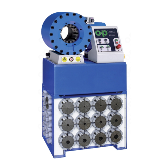
Herunterladen Inhalt Inhalt Diese Seite drucken
Inhaltsverzeichnis

Werbung

Verfügbare Sprachen

Verfügbare Sprachen

Manuale d'uso
e manutenzione
00008MGI
000132GI
Cod.:
MATRICOLA
1
Pag.:
IstruzIonI orIGInalI
ANNO
AVVERTIMENTO!
Chiunque usi questo apparecchio è
obbligato a leggre queste istruzioni,
ne va della sua sicurezza.
1
Cap.:

Werbung

Inhaltsverzeichnis
loading

Inhaltszusammenfassung für OP TUBOMATIC H135 EL

  • Seite 1 000132GI Cap.: Cod.: Pag.: Manuale d’uso e manutenzione 00008MGI IstruzIonI orIGInalI MATRICOLA ANNO AVVERTIMENTO! Chiunque usi questo apparecchio è obbligato a leggre queste istruzioni, ne va della sua sicurezza.
  • Seite 2 Copiare il contenuto senza modificarlo e riportando OP come titolare del copyright. OP si riserva il diritto di apportare modifiche o miglioramenti alla relativa documentazione senza obbligo di preavviso. Richieste di autorizzazioni, ulteriori copie di questo manuale o di informazioni tecniche sullo stesso, devono essere indirizzate a: OP s.r.l.
  • Seite 3 000133GI Cap.: Cod.: Pag.: SOMMARI E INDICI 1 - Premessa ..................... 2 soMMarI E InDICI ............................ 3 Indice numerico dei riferimenti ....................... 5 Il DoCuMEnto E I DEstInatarI ......................6 scopo e struttura del documento ......................6 Caratteristiche del personale ......................... 7 sIMBolI E sEGnalEtICa ........................
  • Seite 4 000133GI Cap.: Cod.: Pag.: 6 - Strumentazione ..................26 ConDIzIonI GEnEralI .......................... 26 Equipaggiamento ..........................27 - Magazzino e cambio rapido brevettato: ..................... 27 tabella: morsetti di raccordatura mm / pollici ..................27 7 - Funzionamento ..................28 ConDIzIonI GEnEralI .......................... 28 Messa in servizio ..........................
  • Seite 5 000133GI Cap.: Cod.: Pag.: Indice numerico dei riferimenti 01, centralina idraulica......................12, 16, 22, 25, 41 04, cilindro oleodinamico ........................15, 22, 41 06, morsetti ................ 15, 16, 19, 20, 25, 27, 28, 34, 35, 36, 37, 39, 41 07, golfari ................................15 08, motore ..........................
  • Seite 6 000003BI Cap.: Cod.: Pag.: IL DOCUMENTO E I DESTINATARI Il presente documento è destinato a figure professionali che per espe- rienza o qualifica sanno operare in conformità alle più comuni norme di sicurezza ed alle specifiche competenze; si presuppone che ogni persona abbia le conoscenze base relative al suo ruolo.
  • Seite 7 000003BI Cap.: Cod.: Pag.: Caratteristiche del personale la persona che si occupa del funzionamento della macchina, deve avere ricevuto un training professionale specifico oppure possedere un’adeguata esperienza maturata su macchine di questo tipo. Qualora, per qualsiasi motivo, all’atto dell’installazione e/o avviamento dell’impianto NON sia stato effettuato un training di addestramento, il °C >...
  • Seite 8 000005BI Cap.: Cod.: Pag.: SIMBOLI E SEGNALETICA sul manuale e/o in alcuni casi sulla macchina, le zone di pericolo vengono indicate con segnaletica, targhette, simboli o icone che rap- presentano il pericolo o l’obbligo. ad esempio l’obbligo di consultazione del documento, che deve essere reperibile per futuri utilizzi e non deve essere in alcun modo deteriorata.
  • Seite 9: Campo Di Impiego

    Cod.: Pag.: CAMPO DI IMPIEGO la OP s.r.l. declina ogni responsabilità per danni di qualunque tipo che dovessero derivare da operazioni non corrette o imprudenti. La macchina NON DEVE essere utilizzata da personale inesperto, oppure esperto ma che svolga operazioni sulla macchina non in accordo con quanto descritto nel presente manuale e nelle documentazioni allegate.
  • Seite 10 - Usare la macchina o parti di essa con pressioni più elevate di quelle tarate e stabilite dal costruttore. la OP s.r.l. declina ogni responsabilità per danni di qualunque tipo che dovessero derivare da operazioni non corrette o imprudenti. L’attrezzatura, se usata in modo improprio, può essere pericolosa, può...
  • Seite 11: Condizioni Generali

    000008AI Cap.: Cod.: Pag.: 2 - Caratteristiche CONDIZIONI GENERALI La descrizione delle caratteristiche della macchina consente di individuare i componenti principali della stessa, per affinare la terminologia tecnica utilizzata nel manuale. la terminologia tecnica viene raccolta nel capitolo soMMarI E InDICI. nel capitolo CarattErIstICHE si troveranno informazioni sulla com- posizione macchina, le caratteristiche, le dimensioni e l’identificazione.
  • Seite 12: Caratteristiche Tecniche

    000134FI Cap.: Cod.: Pag.: DESCRIZIONE MACCHINA E REGOLAZIONI Caratteristiche tecniche Forza di pressatura ..........315 ton (345 us tons) lunghezza morsetti .............. 100 mm apertura dei morsetti ............Ø + 43 mm (aggiungere questo valore al diametro minimo del morsetto che si vuole utilizzare, il risultato è...
  • Seite 13 000134FI Cap.: Cod.: Pag.: Disegni di ingombro le misure sono espresse in mm. sul manuale vengono indicate Ingresso allacciamento linea elettrica le misure di massima e dove necessario le distanze di sicurezza o ingombri necessari alla manutenzione. le misure precise della macchina Posizione operatore o posto di lavoro e/o atrezzatura sono riportate sui disegni di progetto eventualmente...
  • Seite 14 (stracci, scatole, attrezzature ecc..). I dati tecnici riportati sul presente manuale non sostituiscono comunque quelli riportati sulle targhette a bordo macchina. ® MODEL oP srl SERIAL N° VIa DEl sErPEntE, 97 25131 BrEsCIa (ItalY) tel. +39.030.35.80.401 YEAR Fax +39.030.35.80.838...
  • Seite 15 000136CI Cap.: Cod.: Pag.: Descrizione macchina e impianti Questa macchina consente di raccordare, tramite un sistema di pressa- tura, raccordi metallici con tubi oleopneumatici ad alta o bassa pressione compatibili con il campo di impiego e le caratteristiche tecniche. la macchina è composta essenzialmente da: - Gruppo pressatura Il gruppo di pressatura è...
  • Seite 16 000136CI Cap.: Cod.: Pag.: - Centralina idraulica la centralina idraulica 01 è posta nella parte inferiore della macchina ed è predisposta del serbatoio, livello, tappo di carico con asta per livello olio e tappo di scarico. sul coperchio sono montati i componenti oleodinamici, valvole ed elettrovalvole, nonchè...
  • Seite 17 000012CI Cap.: Cod.: Pag.: 3 - Antinfortunistica e Sicurezze CONDIZIONI GENERALI La macchina è stata costruita secondo le più severe norme antinfortu- nistiche e corredata dei dispositivi di sicurezza idonei alla protezione di componenti e operatori. Per ovvie ragioni non è possibile prevedere la molti- tudine di installazioni e di ambienti in cui la macchina sarà...
  • Seite 18 000012CI Cap.: Cod.: Pag.: ZONE ED OPERAZIONI A RISCHIO Condizioni d’installazione la macchina non può essere installata all'aperto o in condizioni ambien- tali avverse (sole, pioggia, vento, ecc..); inoltre devono essere rispettate le distanze di sicurezza per evitare situazioni di pericolo. Accertarsi inoltre dell'assenza di eventuali interferenze elettromagnetiche.
  • Seite 19 000012CI Cap.: Cod.: Pag.: Macchina in movimento la macchina in funzione rappresenta un potenziale pericolo per cui è assolutamente VIEtato farla funzionare a vuoto, fare manutenzione oppure effettuare pulizie con la macchina in funzione. La macchina in funzione ha necessariamente mo- vimenti di pressatura a vista, che per ovvie ragioni operative non possono essere protetti attivamente;...
  • Seite 20: Rischi Residui

    000013BI Cap.: Cod.: Pag.: RISCHI RESIDUI nonostante le avvertenze e i sistemi di sicurezza che il Costruttore ha adottato, restano sempre alcuni rischi residui non eliminabili . Questi rischi vengono elencati nella tabella seguente con alcuni sug- gerimenti per prevenirli. Tabella: rischi residui ANALISI DEL RISCHIO E DESCRIZIONE RIMEDIO SUGGERITO...
  • Seite 21: Sollevamento E Trasporto

    000014BI Cap.: Cod.: Pag.: 4 - Sollevamento e Trasporto CONDIZIONI GENERALI Sollevamento Dove indicato e/o dove predisposto sono inseriti e/o inseribili dei golfari ai quali si può ancorare direttamente un gancio (se adatto al passaggio) o agganciare dei grilli come rappresentato in figura. Il sollevamento deve essere effettuato esclusivamente da personale specializzato (imbracatori, gruisti, auto- trasportatori, ecc...)
  • Seite 22 000137DI Cap.: Cod.: Pag.: SOLLEVAMENTO SPECIFICO GRUPPI Il sollevamento va effettuato rispettando le condizioni generali descritte precedentemente ed ancorandosi alle posizioni previste sul manuale, sulla macchina o sugli imballi. la macchina è composta da un gruppo soltanto che comprende la centralina idraulica 01, il cilindro oleodinamico 04, cassetta elettrica 22 e pannello comandi 13.
  • Seite 23: Verifiche Preliminari

    000016CI Cap.: Cod.: Pag.: 5 - Installazione CONDIZIONI GENERALI Modalità d’installazione l’installazione della macchina deve essere eseguita in funzione delle esigenze del Cliente e del luogo in cui la macchina verrà installata. L’operazione deve essere effettuata da personale spe- cializzato; è comunque opportuno rispettare quanto detto nel presente manuale.
  • Seite 24 000016CI Cap.: Cod.: Pag.: - Verificare che il motore 08 giri dopo avere collegato la spina. nel caso il motore non giri, procedere effettuando i seguenti controlli: 1. Controllare che il pulsante di emergenza non sia bloccato. 2. Controllare che la presa di corrente a muro corrisponda ai poli della presa macchina.
  • Seite 25 000099BI Cap.: Cod.: Pag.: Procedura di installazione l’installazione viene effettuata tenendo in debita considerazione quanto esposto precedentemente e seguendo per ordine la seguente procedura: - Posizionare e livellare la macchina. - Pulire in particolare le parti mobili che sfregano fra loro, eventualmente lubrificandole, come descritto nel capitolo MANUTENZIONE.
  • Seite 26 000018AI Cap.: Cod.: Pag.: 6 - Strumentazione CONDIZIONI GENERALI Conoscere a fondo la struMEntazIonE è una delle prime regole per evitare danni alla macchina e all’operatore. Pertanto si consiglia di leggere attentamente quanto descritto nel manuale e in caso di incertezza o discor- danza di informazioni richiedere notizie più...
  • Seite 27 000138CI Cap.: Cod.: Pag.: Equipaggiamento “N” la macchina può essere dotata di dispositivi (oPtIonal) che agevo- lano la preparazione o la lavorazione come ad esempio: - la pinza “N” per il cambio morsetti economico (oPtIonal) - dispenser portagusci “R” (oPtIonal) per cambio morsetti econo- mico.
  • Seite 28 000308AI Cap.: Cod.: Pag.: 7 - Funzionamento CONDIZIONI GENERALI Prima di procedere al controllo dei movimenti e delle funzioni della macchina è necessario effettuare una serie di verifiche essenziali e conoscere a fondo il capitolo struMEntazIonE e le funzioni che vengono abilitate dai comandi, nonché...
  • Seite 29: Pannello Comandi

    000089DI Cap.: Cod.: Pag.: PANNELLO COMANDI PULSANTE “START” PULSANTE “STOP” PULSANTE DI ARRESTO DI EMERGENZA PULSANTE DI APERTURA PULSANTE DI CHIUSURA LED VERDE - PROXIMITY 1 “RAGGIUNGIMENTO QUOTA” LED ROSSO - PROXIMITY 1 GUASTO “RALLENTA- MENTO” LED ROSSO - PROXIMITY 2 GUASTO” “RAGGIUNGI- MENTO QUOTA”...
  • Seite 30 000089DI Cap.: Cod.: Pag.: DESCRIZIONE COMANDI DEL PANNELLO • E01 - PULSANTE “START”: Questo pulsante va premuto all’ ini- zio della fase di lavoro, dopo un arresto d’ emergenza o dopo un assenza di corrente. • E02 - PULSANTE “STOP”: Premendo questo pulsante si ha l’ar- resto immediato della raccordatrice •...
  • Seite 31 000089DI Cap.: Cod.: Pag.: • E11 - POTENZIOMETRO DI REGOLAZIONE RIAPERTURA: regola la riapertura della macchina. N.B.: Se il potenziometro E11 viene posizionato su meno la regolazione viene disabilitata. • E12 - POTENZIOMETRO TEMPO DI PRESSATURA : Consente di regolare il tempo di pressatura. Il tempo di pressatura è...
  • Seite 32: Caratteristiche

    000089DI Cap.: Cod.: Pag.: DESCRIZIONE COMANDI DEL NONIO nonio di regolazione 21: - Per ottenere il diametro di pressatura si deve agire sul volantino di regolazione: girandolo verso destra si ha una diminuzione del diame- tro di pressatura; girandolo verso sinistra si ottiene un aumento del diametro di pressatura.
  • Seite 33: Procedura Operativa

    000089DI Cap.: Cod.: Pag.: PROCEDURA OPERATIVA 1. Accertarsi quale sia il diametro finale di pressatura ( il diametro finale è fornito dai costruttori dei raccordi; seguire le loro indica- zioni) e inserire la serie di morsetti opportuna (tabella di Morsetti di raccordatura) nel capitolo “struMEntazIonE”.
  • Seite 34 000088BI Cap.: Cod.: Pag.: SOSTITUZIONE DEI MORSETTI MANUALE Inserimento e rimozione dei morsetti con cambio manuale 1. Far retrocedere il pistone, in modo da arrivare a fine corsa; quindi arrestare la macchina disinserendo l’”Interruttore generale”. 2. Inserire l’apposita chiave “T” agganciando il dado frontale situato sul portamorsetti, tirare frontalmente per far sganciare e fuoriuscire il morsetto dalla sua sede.
  • Seite 35 000088BI Cap.: Cod.: Pag.: SOSTITUZIONE DEI MORSETTI CON CAMBIO RAPIDO ECONOMICO Rimozione dei morsetti con cambio rapido economico N.B. Avviare la macchina prima di iniziare la procedura di cambio rapido. 1. regolare il nonio di regolazione 21 sullo zero. 2. Premere il pulstante di chiusura E05 Far avanzare il pistone, in modo da arrivare con i morsetti chiusi.
  • Seite 36 000088BI Cap.: Cod.: Pag.: INSERIMENTO DEI MORSETTI CON CAMBIO RAPIDO ECONOMICO N.B. questo sistema, essendo sprovvisto di guida di centraggio, richiede più attenzione da parte dell’ope- ratore che dovrà assicurarsi che il cambio rapido sia posizionato correttamente in fase di inserimento. N.B.
  • Seite 37 000088BI Cap.: Cod.: Pag.: SOSTITUZIONE DEI MORSETTI CON CAMBIO RAPIDO BREVETTATO Rimozione dei morsetti con cambio rapido brevettato N.B. Avviare la macchina prima di iniziare la procedura di cambio rapido. 1. regolare il nonio di regolazione 21 sullo zero. 2. Far avanzare il pistone premendo E05, in modo da arrivare con i morsetti chiusi a pacco.
  • Seite 38 000088BI Cap.: Cod.: Pag.: 5. Sfilare la pinza brevettata 11 dalla flangia anteriore. 6. Infilare i morsetti nei gusci 12 tenendo presente che i perni devono scorrere nella guida ricavata sul guscio stesso, e quindi fare una piccola rotazione in senso orario. 7.
  • Seite 39 000088BI Cap.: Cod.: Pag.: INSERIMENTO DEI MORSETTI CON CAMBIO RAPIDO BREVETTATO N.B. Avviare la macchina prima di iniziare la procedura di cambio rapido.. 1. Verificare che la macchina sia completamente aperta con il nonio di regolazione 21 regolato sullo zero. 2.
  • Seite 40 °C > 80 000021BI Cap.: Cod.: Pag.: °C 8 - Manutenzione STOP IMPORTANT IMPORTANT PULIRE E LUBRIFICARE CONDIZIONI GENERALI TO CLEAN AND TO LUBRIFICATE Le operazioni di manutenzione e lubrificazione vanno eseguite a mac- china ferma e togliendo qualsiasi tipo di alimentazione (elettrica, pne umatica, etc), se non diversamente indicato.
  • Seite 41: Manutenzione Ordinaria

    000090AI Cap.: Cod.: Pag.: Manutenzione ordinaria SIMBOLI E FREQUENZA DESCRIZIONE MANUTENZIONE E CONTROLLI - Effettuare giornalmente la pulizia dell’ambiente e del posto di lavoro, 24 h delle targhette tecniche e antinfortunistiche, dei pannelli di comando e in generale di tutta la macchina (esempio una maniglia unta o sporca può...
  • Seite 42 000024AI Cap.: Cod.: Pag.: Lubrificanti e simboli Tabella: lubrificanti e simboli Rif. Simbolo Descrizione Lubrificante UNI 7164 DIN 30600 ICONA ISO 34978 ISO 7000 olIo MoBIl oIl DtE 25 HM46 idraulico aGIP oso 46 olIo MoBIl VaCtra 4 G220 per guide aGIP EXIDIa HG320 olIo tEllus sHEll 22...
  • Seite 43 000025AI Cap.: Cod.: Pag.: STOCCAGGIO E SMANTELLAMENTO Stoccaggio macchina o sosta prolungata Qualora la macchina non venga utilizzata immediatamente o venga stivata per lunghi periodi verificare che sia correttamente imballata. Lo stoccaggio deve essere effettuato in luoghi chiusi, ma ben ventilati e che non presentino particolari caratteristiche dannose ai componenti della macchina, in particolare quelli elettronici.
  • Seite 44 000035AI Cap.: Cod.: Pag.: 9 - Catalogo Ricambi CONDIZIONI GENERALI Per la richiesta delle parti di ricambio comunicare: - Macchina Modello - Matricola - numero del particolare - numero di pagina - Descrizione del particolare - Quantità desiderata - Per il materiale elettrico indicare inoltre: tensione (Volt) e frequenza (Hz).
  • Seite 45 000139CI Cap.: Cod.: Pag.:...
  • Seite 46 000139CI Cap.: Cod.: Pag.:...
  • Seite 47 000139CI Cap.: Cod.: Pag.: Pos. Code/CODICE Pos. Code/CODICE GUARNIPOMPA001 TUBH130ELS23712 POMPAINGR11263 TUBH130ELS23715 OMTND16 TUBH135ELS23417 TAPPOCAR112000 TUBH135ELS23418 TUBH144ELS19434 OMTRG14 MASSELLO014 OMTRG13 V92Z004 OMTA300 RACCRIGIDO026 OMTLS300 BOCCOLA1018318 CONSOL000 FERV02405 N021208 PP012D NIPPLOCIL029 RONDBONDED38000 FILTROASP008 RONDBONDED34000 NIPPLOCON003 NIPPLOCIL000 RACCRIGIDO025 NIPPLOCIL010 FILTROASP004 NIPPLOCIL021 ME075HP001 DUDS5S7C...
  • Seite 48 000139CI Cap.: Cod.: Pag.: Pos. Code/CODICE TUBH130ELS23734 TUBH130ELS23757 TUBH130ELS23735...
  • Seite 49 000139CI Cap.: Cod.: Pag.: Pos. Code/CODICE Pos. Code/CODICE Pos. Code/CODICE TUBH130ELS23701 TUBH135ELS23403 FASCIAG370000 TUBH130ELS23784 FASCIAG250003 TUBH135ELS23405 TUBH80S13503 RASCHIA250001 TUBH135ELS23404 TUB265S001013 GUARNI370000 TUBH135ELS23406 TUBH80ELS13502 TUBH135ELS23407 RACCPNE10000 TUBH144ELS19405 TUBH135ELS23408...
  • Seite 50 000139CI Cap.: Cod.: Pag.: Pos. Code/CODICE Pos. Code/CODICE INDICATOREPOS003 TUBH135ELS23410 MANOPOLAMD51 TUBH135ELS23413 FE107434 TUBH135ELS23416 MOLLA92533125 TUBH130ELS23722 ELXS1N08PB340 TUBH130ELS23726 TUBH130ELS23728...
  • Seite 51 000139CI Cap.: Cod.: Pag.:...
  • Seite 52 000139CI Cap.: Cod.: Pag.:...
  • Seite 53 000093AI Cap.: Cod.: Pag.: 10 - Elenco allegati oltre al presente manuale d’uso e manutenzione, in allegato e/o a richiesta viene fornita (se applicabile) la seguente documentazione: - Dichiarazione di conformità; - Schemi elettrici; - Schemi idraulici; - Schemi pneumatici; - Istruzioni per il cambio voltaggio;...
  • Seite 54 000825BI Cap.: Cod.: Pag.:...
  • Seite 55: Dichiarazione Di Conformita

    Dichiariamo che il Fascicolo tecnico è costituito presso oP s.r.l Via del serpente 97, 25131 BrEsCIa We declare that the technical documentation is established c/o oP s.r.l. Via del serpente 97, 25131 BrEsCIa La persona responsabile del fascicolo tecnico è il Sig. Massimo Ziliani Resp. Ufficio Tecnico.
  • Seite 56 000825BI Cap.: Cod.: Pag.:...
  • Seite 57: Hydraulic System Diagram

    000140AI Cap.: Cod.: Pag.: SCHEMA IDRAULICO HYDRAULIC SYSTEM DIAGRAM...
  • Seite 58 000141AI Cap.: Cod.: Pag.: SCHEMA ELETTRICO ELECTRIC SYSTEM DIAGRAM...
  • Seite 59 000141AI Cap.: Cod.: Pag.: SCHEMA ELETTRICO ELECTRIC SYSTEM DIAGRAM...
  • Seite 60 000141AI Cap.: Cod.: Pag.: SCHEMA ELETTRICO ELECTRIC SYSTEM DIAGRAM...
  • Seite 61 000075AI Cap.: Cod.: Pag.: ISTRUZIONI PER IL CAMBIO VOLTAGGIO INSTRUCTION ON HOW TO CHANGE THE SUPPLY VOLTAGE 50 Hz 60Hz collegamento ∆ collegamento ∆ tensione minima 215 V tensione minima 215 V tensione massima 240 V tensione massima 290 V collegamento Ү...
  • Seite 62 000097AI Cap.: Cod.: Pag.: ISTRUZIONI PER IL LAVAGGIO ED INGRASSAGGIO TUBOMATIC INSTRUCTIONS FOR CLEANING AND GREASING TUBOMATIC 1. Regolare il fine corsa sullo zero. 2. Chiudere la macchina facendo avanzare il pistone. 3. agganciare la pinza ai dadi posti sul porta morsetti. 1.
  • Seite 63 000097AI Cap.: Cod.: Pag.: 7. Collegare l’aria compressa Max 7 bar alla pistola. 8. togliere carter frontale. 7. Connect the compressed air Max 7 bars per pump. 8. remove the front safety guard. 9. Svitare raccordo posizionato sotto flangia. 9. Unfasten fitting located under the flange. 10.
  • Seite 64 000097AI Cap.: Cod.: Pag.: 12. lavare dalla parte posteriore l’interno della macchina. 12. Clean the inner part of the machine from the rear side. 13. Soffiare. 13. Blow. 14. Ripetere l’operazione n°12 e n°13 fino a che non si noterà una fuoriuscita di liquido di lavaggio di colore chiaro quindi il più...
  • Seite 65: Accessories

    000097AI Cap.: Cod.: Pag.: 17. ad ingrassaggio terminato chiudere la macchina. 17. Sfilare la pinza facendo leva leggermente verso il basso. 17. togliere i 2 spessori. 17. Ingrassare gli otto settori anteriori del portamorsetti. 17. Fare un paio di cicli d’apertura e chiusura macchina a vuoto 17.
  • Seite 66: Cambio Filtro

    000098CI Cap.: Cod.: Pag.: CAMBIO FILTRO E OLIO OIL AND FILTER CHANGE CaMBIo FIltro 1. Quando si sostituiscono i filtri è consigliabile cambiare anche l’ olio. 2. sollevare il coperchio del serbatoio come indicato nella prossima figura. 3. Svitare i filtri indicati e rimuoverli. 4.
  • Seite 67 000098CI Cap.: Cod.: Pag.: SCHEMA PER CAMBIO OLIO E FILTRO OIL AND FILTER CHANGE DIAGRAM TAPPO DI CARICO CON ASTINA FILLING CAP WITH DIPSTICK FILTRO FILTER TAPPO DI SCARICO OLIO ( SUL RETRO ) DRAINING PLUG ( ON THE REAR )
  • Seite 68 001032AI Pag.: Cap.: Cod.: MANUALE DELL’INDICATORE DI POSIZIONE ELETTRONICO DD51-E Indicatori di posizione elettronici a comando diretto ISTRUZIONI D’USO ELESA S.p.A. Via Pompei, 29 20900 Monza (MB) Italia Tel. +39 039 2811.1 Fax +39 039 836351 info@elesa.com • • • •...
  • Seite 69 001032AI Pag.: Cap.: Cod.: DD51-E Indicatori di posizione elettronici a comando diretto 1. Istruzioni di sicurezza 3. Installazione Il prodotto è stato progettato e costruito in conformità alle normative vigenti. 1. Eseguire un foro Ø 6x10 mm di profondità nel corpo della macchina con Il prodotto esce dalla fabbrica pronto per l’uso e conforme alle norme di interasse 22 mm dall’albero per l’alloggiamento del piolino posteriore di sicurezza.
  • Seite 70: Selezione Dell'unità Di Misura

    001032AI Pag.: Cap.: Cod.: DD51-E Indicatori di posizione elettronici a comando diretto 7. Modalità di lavoro 0 _ 0 _ _ È possibile modi care la funzione della combinazione Selezione modalità di misura assoluta / incrementale di tasti impostando il parametro 0_0__ Premere il tasto per selezionare la modalità...
  • Seite 71: Programmazione Dei Parametri

    001032AI Pag.: Cap.: Cod.: DD51-E Indicatori di posizione elettronici a comando diretto 8. Modalità di programmazione 8.2 Programmazione dei parametri Premere il tasto per 3 secondi Premere il tasto per 3 secondi per accedere alla modalità di Inserire la password 22011 (solo se PASS = On ) programmazione.
  • Seite 72 001032AI Pag.: Cap.: Cod.: DD51-E Indicatori di posizione elettronici a comando diretto I parametri disponibili e le relative descrizioni sono riportate nella seguente tabella. Opzioni Valore Opzioni Valore Parametro Descrizione Parametro Descrizione disponibili Standard disponibili Standard Senso di rotazione --o senso orario Password ON : il sistema richiede l’inserimento PASS...
  • Seite 73 000132GG Chapter: Code: Page: Operating and maintenance manual 00008MGG SERIAL N. YEAR WARNING! For safety reasons these instructions must be carefully read by anyone who makes use this equipment.
  • Seite 74 Printing this document or part of it without modifying it. Copying the content without modifying it, indicating OP as the copyright owner. OP reserves the right to make any modification or improvement to this document at any time, without any previ- ous notice.
  • Seite 75 000133GG Cap.: Code.: Page.: CONTENTS AND INDEXES 1 - Introduction ....................2 COntEnts anD inDEXEs ........................3 reference number index ........................5 tHE DOCuMEnt anD intEnDED rEaDErs ..................6 scope and structure of the document ....................6 Personnel characteristics ........................7 sYMBOls anD siGns ..........................
  • Seite 76 000133GG Cap.: Code.: Page.: 6 - Instrumentation ..................26 GEnEral COnDitiOns .......................... 26 Equipping ............................. 27 - Magazine and quick change tools ...................... 27 table: Hose crimping dies mm / inch ....................27 7 - Operation ....................28 GEnEral COnDitiOns .......................... 28 Commissioning .............................
  • Seite 77 000133GG Cap.: Code.: Page.: Reference number index 01, hydraulic unit ........................12, 16, 22, 25, 41 04, hydraulic cylinder ..........................15, 22, 41 06, dies ................15, 16, 19, 20, 25, 27, 28, 34, 35, 36, 37, 39, 41 07, lugs ................................15 08, motor ..........................
  • Seite 78 000003BG Chapter: Code: Page: THE DOCUMENT AND INTENDED READERS this document is intended to be read by professionals whose experience or qualifications allow them to work in conformity with the most common safety standards and specific skills. It is presupposed that each person has the basic knowledge required for their role.
  • Seite 79 000003BG Chapter: Code: Page: Personnel characteristics the person tasked with operating the machine must have received specific professional training or have adequate experience with ma- chines of this type. If, for any reason, when installing and/or starting the plant training has nOt been given the Client is obliged to ask for it and/or make sure that °C >...
  • Seite 80: Symbols And Signs

    000005BG Chapter: Code: Page.: SYMBOLS AND SIGNS in some cases the danger zones are indicated in the manual and/or on the machine in some cases, using signs, plates, symbols, or icons that represent the danger or the obligation. For example, the obligation of consulting the document, which must be available for future use and must not be deteriorated in any way.
  • Seite 81: Range Of Use

    Code: Page: RANGE OF USE OP s.r.l. does not accept any responsibility for any type of damage that may result from incorrect or imprudent operations. The machine MUST NOT be used by unskilled person- nel or experts that do work on the machine that does not comply with the contents of this manual and the annexed documentation.
  • Seite 82 - use the machine it parts thereof at pressures higher than those set and established by the manufacturer. OP s.r.l. does not accept any responsibility for any type of damage that may result from incorrect or imprudent operations. If used incorrectly the equipment can be dangerous, or...
  • Seite 83: General Conditions

    000008AG Chapter: Code: Page: 2 - Characteristics GENERAL CONDITIONS The description of the machine’s characteristics ma- kes it possible to identify its main components and refine the technical terminology used in the manual. the technical terminology is covered in the COntEnts anD inDEXEs chapter.
  • Seite 84: Technical Characteristics

    000134FG Chapter: Code: Page: MACHINE DESCRIPTION AND SETTINGS Technical characteristics Pressing force..............315 tonnes Die length ................100 mm Die opening ............... Ø + 43 mm (Add this value to the minimum diameter of the die you wish to use to obtain the maximum opening in the die) Working capacity on 6 spirals (2 piece) ..........2”...
  • Seite 85 000134FG Chapter: Code: Page: Drawing showing overall dimensions the measurements are expressed in mm. the manual indicates the maximum Electrical line connection entrance. measurements and where necessary the safety distances or spaces required for maintenance. the exact measu- rements of the machine and/or equi- Operator’s position or workstation.
  • Seite 86 NOT be hidden by any objects or items (rags, boxes, equipment, etc.). the technical details given in this manual do not replace those shown on the information plates on the machine. ® MODEL OP srl SERIAL N° VIA DEL SERPENTE, 97 25131 BRESCIA (ITALY) tel. +39.030.35.80.401 YEAR Fax +39.030.35.80.838...
  • Seite 87 000136CG Chapter: Code: Page: Machine and plant description This machine uses a pressing system to join metal hosefittings to high and low pressure oil pneumatic pipes at a pressure that is suitable for the range of use and technical characteristics. in essence the machine comprises: - Pressing unit the pressing unit is made up of a hydraulic cylinder 04 supported by...
  • Seite 88: Hydraulic Unit

    000136CG Chapter: Code: Page: - Hydraulic unit the hydraulic unit 01 is housed on the lower part of the machine. This unit has a level gauge, filling cap, and oil draining cap. The oil hydraulic components, valves and solenoid valves are fitted on the cover, as well as the motor 08 to which the pumps 09 and related submerged filters 10 are connected.
  • Seite 89 000012CG Chapter: Code: Page: 3 - Accident Prevention and Safety GENERAL CONDITIONS this machine is built according to the most severe accident prevention standards and is fitted with safety devices that are suitable for protecting components and operators. For obvious reasons it is not possible to foresee the multitude of installations and environments in which the machine will be installed, and so the Client must provide the Manufacturer with adequate information...
  • Seite 90: Installation Conditions

    000012CG Chapter: Code: Page: RISK ZONES AND OPERATIONS Installation conditions this machine must not be installed out in the open or under adverse ambient conditions (sun, rain, wind, etc.). The safety distances must also be respected to avoid dangerous situations. Also make sure that there is no electromagnetic in- terference.
  • Seite 91 000012CG Chapter: Code: Page: Machine moving When moving the machine poses a potential danger and so it is com- pletely FORBIDDEN to run it empty, do maintenance, or clean it when the machine is running. When the machine is working of necessity it has pressing movements that can be seen and that for obvious operating reasons cannot be actively pro- tected.
  • Seite 92: Residual Risks

    000013BG Chapter: Code.: Page.: RESIDUAL RISKS Despite the warnings and safety systems that the Manufacturer has adopted, there are still some residual risks that cannot be eliminated. These risks are listed in the table below, with some suggestions to avoid them. Table: Residual risks RISK ANALYSIS AND DESCRIPTION SUGGESTED SOLUTION...
  • Seite 93 000014BG Chapter: Code: Page: 4 - Lifting and Transportation GENERAL CONDITIONS Lifting Where indicated and/or provided for, lugs 07 are inserted and/or can be inserted to which a hook or shackle (of correct size) can be anchored correctly, as shown in the figure. Lifting is only to be done by specialist personnel (riggers, crane operators, haulage contractors, etc.).
  • Seite 94 000137DG Chapter: Code: Page: SPECIFIC LIFTING OF UNITS lifting is to be done according to the general conditions described previously and anchoring to the points indicated in the manual on the machine or the packaging. the machine is normally made up of a multiple unit or element that includes the hydraulic unit 01, the hydraulic cylinder 04, branch box 22 and control panel 13.
  • Seite 95: Preliminary Checks

    000016CG Chapter: Code: Page: 5 - Installation GENERAL CONDITIONS Means of installation the machine must be installed to suit the Client’s needs and the place in which the machine is to be installed. This operation must be carried out by specialist per- sonnel.
  • Seite 96 000016CG Chapter: Code: Page: - the motor 08 doesn’t work when the switch is connected : 1. Check whether the emergency button is locked. 2. Check whether the wall switch corresponds to the machine's switch poles. 3. Check whether the fuse of the wall switch is burnt.
  • Seite 97: Installation Procedure

    000099BG Chapter: Code: Page: Installation procedure The installation is done bearing in mind the comments made above, and following the procedure below in the order indicated: - Position and level the machine. - Clean especially the moving parts that rub against one another and lubricate if necessary as described in the MaintEnanCE chapter.
  • Seite 98 000018AG Chapter: Code: Page: 6 - Instrumentation GENERAL CONDITIONS Full knowledge of the instruMEntatiOn is one of the prime rules to avoid damage the machine and the operator. We therefore recommend reading this manual carefully and if there is any uncertainty or discrepancy in the information, ask the manufacturer for more specific information.
  • Seite 99 000138CG Chapter: Code: Page: Equipping “N” The machine can be equipped with (OPTIONAL) devices that facilitate preparation or machining, such as, for example: - Change tool “N” for replacing the dies in economic mode. (OPTIONAL) - the shell carrying dispenser “R” (OPTIONAL) - the patented quick change tool 11 for changing the dies in rapid mode ”...
  • Seite 100 000308AG Chapter: Code: Page: 7 - Operation GENERAL CONDITIONS Before starting to control the machine’s movements and functions a se- ries of essential checks must be carried out and a thorough knowledge must be gained of the instruMEntatiOn chapter and the functions that are enabled by the commands, as well as the positioning of the stOP buttons and the EMErGEnCY devices.
  • Seite 101: Control Panel

    000089DG Chapter: Code: Page: CONTROL PANEL “START” BUTTON “STOP” BUTTON “EMERGENCY STOP” “OPEN” BUTTON “CLOSE” BUTTON GREEN LED - PROXIMITY 1 “WORKING DIMENSION” RED LED - PROXIMITY 1 FAILURE “SLOWDOWN” RED LED - PROXIMITY 2 FAILURE “WORKING DI- MENSION” RED LED - MOTOR ENGINE OVERHEATED LAMP WHITE - MACHINE POWERED POTENTIOMETER FOR REOPENING REGULATION CRIMPING TIME POTENTIOMETER...
  • Seite 102 000089DG Chapter: Code: Page: DESCRIPTION OF PANEL CONTROLS: • E01 - “START” BUTTON: this button should be pressed to start working after an emergency stop or after a power outage. • E02 - “STOP” BUTTON: When this button is pressed the fitting machine stops immediately.
  • Seite 103 000089DG Chapter: Code: Page: • E11 – POTENTIOMETER FOR REOPENING REGULATION: it sets the reopening of the machine. Note: When the potentiometer E11 is positioned on minus, the regulation is disabled. • E12 - CRIMPING TIME POTENTIOMETER: it allows to define the crimping time.
  • Seite 104 000089DG Chapter: Code: Page: VERNIER DIAL CONTROLS vernier dial 21: - Use the knurled adjusting ring nut to obtain the required diameter, turning it clockwise to reduce the swaging diameter or counterclockwise to increase it. Use the knurled flywheel to adjust the pressing diameter (pos. D) and the electronic position indicator display (pos.
  • Seite 105: Operating Procedure

    000089DG Chapter: Code: Page: OPERATING PROCEDURE 1. Decide the final crimp diameter required (the final crimp diameter is supplied by the producers of the fittings; follow their instructions) and insert the proper set of dies (see chapter “ISTRUMENTATION”) 2. Insert the hose with the fittings and bush, already prefitted, between the dies.
  • Seite 106 000088BG Chapter: Code: Page: MANUAL DIES REPLACEMENT Insert and remove die with manual change tool 1. Open the machine completely, then stop the machine and disconnecting power with the “Power switch” 2. insert the suitable wrench “T” hooking the front nut placed on the dieholder, draw frontally so as to unhook and release the die from its housing.
  • Seite 107: Die Replacement With Standard Quick Change Tool

    000088BG Chapter: Code: Page: DIE REPLACEMENT WITH STANDARD QUICK CHANGE TOOL Die removal with standard quick change tool N.B. Start the machine before beginning the quick change die process. 1. adjust the vernier dial 21 to zero. 2. Push the button E05. Make the piston move forward so as to arrive with the closed dies.
  • Seite 108: Die Insertion With Standard Quick Change Tool

    000088BG Chapter: Code: Page: DIE INSERTION WITH STANDARD QUICK CHANGE TOOL N.B. This device, being without a centering guide, requires more attention by operator that must make sure that quick change is correctly positioned during insertion. N.B. Start the machine before beginning the quick change die process.
  • Seite 109: Die Replacement With Patented Quick Change Tool

    000088BG Chapter: Code: Page: DIE REPLACEMENT WITH PATENTED QUICK CHANGE TOOL Die removal with patented quick change tool N.B. Start the machine before beginning the quick change die process. 1. adjust the vernier dial 21 to zero. 2. Push the button E05. Make the piston move forward so as to arrive with the closed dies.
  • Seite 110 000088BG Chapter: Code: Page: 5. Draw the patented quick change tool out of the holes of the front flange. 6. Insert the dies in the shell, considering that the pins should slide in the guide obtained on the same shells 12, then rotate lightly clockwise.
  • Seite 111: Die Insertion With Patented Quick Change Tool

    000088BG Chapter: Code: Page: DIE INSERTION WITH PATENTED QUICK CHANGE TOOL N.B. Start the machine before beginning the quick change die process. 1. Verify that the machine is completely open with the vernier dial 21 set to zero. 2. Chose the new set of dies and then insert the patented quick change tool taking care that the 8 pins tally in the front holes of the dies 06.
  • Seite 112 °C > 80 000021BG Chapter: Code: Page: °C 8 - Maintenance STOP IMPORTANT IMPORTANT PULIRE E LUBRIFICARE GENERAL CONDITIONS TO CLEAN AND TO LUBRIFICATE Maintenance and lubrication operations are to be carried out with the machine stopped and power supply switched off, unless otherwise indicated.
  • Seite 113 000090AG Chapter: Code: Page: Routine maintenance SYMBOLS AND FREQUENCY DESCRIPTION OF MAINTENANCE AND CHECKS - Each day clean the working environment and workplace, technical 24 h and accident prevention information plates, control panels and the whole machine in general (e.g. an oily or dirty handle may give rise to a dangerous situation).
  • Seite 114: General Check

    000024AG Chapter : Code : Page: Lubricants and symbols Table: lubricant e symbols Ref. Symbol Description Lubricant UNI 7164 DIN 30600 ICON ISO 34978 ISO 7000 MOBil Oil DtE 25 HM46 Hydraulic aGiP OsO 46 MOBil VaCtra 4 G220 lubricating for guide aGiP EXiDia HG320 tEllus sHEll 22 For lubrication...
  • Seite 115: Ensure That The In Inoperative Or Stored Machine Is Completely Open

    000025AG Chapter: Code: Page: STORAGE AND DISASSEMBLY Storing the machine or prolonged stoppage if the machine is not to be used immediately or is to be stored for long periods of time, check that it is packed correctly. it must be stored in closed spaces that are well ventilated and that do not present characteristics that are harmful to the machine’s components, especially the electronic parts.
  • Seite 116 000035AG Chapter: Code: Page: 9 - Spare Parts Catalog GENERAL CONDITIONS By request for spare parts please mention: - type of machine - serial number - Part number of the spare part - Page number - item description - required quantity - For the electric material please mention in addition: the voltage (Volt) and the frequency (Hz) For warranty coverage purposes only original spare...
  • Seite 117 000139CG Chapter: Code: Page:...
  • Seite 118 000139CG Chapter: Code: Page:...
  • Seite 119 000139CG Chapter: Code: Page: Pos. Code/CODICE Pos. Code/CODICE GUARNIPOMPA001 TUBH130ELS23712 POMPAINGR11263 TUBH130ELS23715 OMTND16 TUBH135ELS23417 TAPPOCAR112000 TUBH135ELS23418 TUBH144ELS19434 OMTRG14 MASSELLO014 OMTRG13 V92Z004 OMTA300 RACCRIGIDO026 OMTLS300 BOCCOLA1018318 CONSOL000 FERV02405 N021208 PP012D NIPPLOCIL029 RONDBONDED38000 FILTROASP008 RONDBONDED34000 NIPPLOCON003 NIPPLOCIL000 RACCRIGIDO025 NIPPLOCIL010 FILTROASP004 NIPPLOCIL021 ME075HP001 DUDS5S7C...
  • Seite 120 000139CG Chapter: Code: Page: Pos. Code/CODICE TUBH130ELS23734 TUBH130ELS23757 TUBH130ELS23735...
  • Seite 121 000139CG Chapter: Code: Page: Pos. Code/CODICE Pos. Code/CODICE Pos. Code/CODICE TUBH130ELS23701 TUBH135ELS23403 FASCIAG370000 TUBH130ELS23784 FASCIAG250003 TUBH135ELS23405 TUBH80S13503 RASCHIA250001 TUBH135ELS23404 TUB265S001013 GUARNI370000 TUBH135ELS23406 TUBH80ELS13502 TUBH135ELS23407 RACCPNE10000 TUBH144ELS19405 TUBH135ELS23408...
  • Seite 122 000139CG Chapter: Code: Page: Pos. Code/CODICE Pos. Code/CODICE INDICATOREPOS003 TUBH135ELS23410 MANOPOLAMD51 TUBH135ELS23413 FE107434 TUBH135ELS23416 MOLLA92533125 TUBH130ELS23722 ELXS1N08PB340 TUBH130ELS23726 TUBH130ELS23728...
  • Seite 123 000139CG Chapter: Code: Page:...
  • Seite 124 000139CG Chapter: Code: Page:...
  • Seite 125 000093AG Chap: Code: Page: 10 - List of annexes In addition to this operating and maintenance manual, the following do- cumentation is supplied as annexes and/or upon request (if applicable): - Wiring diagrams - Hydraulic diagrams - Pneumatic diagrams - Declaration of conformity - instruction on how to change the supply voltage - Instruction on how to change the filter and for cleaning and greasing ( H Version)
  • Seite 126 000825BG Chap.: Code: Page:...
  • Seite 127 Dichiariamo che il Fascicolo Tecnico è costituito presso OP s.r.l Via del Serpente 97, 25131 BRESCIA We declare that the technical documentation is established c/o OP s.r.l. Via del serpente 97, 25131 BRESCIA La persona responsabile del fascicolo tecnico è il Sig. Massimo Ziliani Resp. Ufficio Tecnico.
  • Seite 128 000825BG Chap.: Code: Page:...
  • Seite 129 000140AG Chap.: Code: Page: SCHEMA IDRAULICO HYDRAULIC SYSTEM DIAGRAM...
  • Seite 130 000141AG Chap.: Code: Page: SCHEMA ELETTRICO ELECTRIC SYSTEM DIAGRAM...
  • Seite 131 000141AG Chap.: Code: Page: SCHEMA ELETTRICO ELECTRIC SYSTEM DIAGRAM...
  • Seite 132 000141AG Chap.: Code: Page: SCHEMA ELETTRICO ELECTRIC SYSTEM DIAGRAM...
  • Seite 133 000075AG Chap.: Code: Page: ISTRUZIONI PER IL CAMBIO VOLTAGGIO INSTRUCTION ON HOW TO CHANGE THE SUPPLY VOLTAGE 50 Hz 60Hz collegamento ∆ collegamento ∆ tensione minima 215 V tensione minima 215 V tensione massima 240 V tensione massima 290 V collegamento Ү...
  • Seite 134 000097BG Chap.: Code: Page: ISTRUZIONI PER IL LAVAGGIO ED INGRASSAGGIO TUBOMATIC INSTRUCTIONS FOR CLEANING AND GREASING TUBOMATIC 1. Regolare il fine corsa sullo zero. 2. Chiudere la macchina facendo avanzare il pistone. 3. agganciare la pinza ai dadi posti sul porta morsetti. 1.
  • Seite 135 000097BG Chap.: Code: Page: 7 Collegare l’aria compressa Max 7 bar alla pistola. 8 togliere carter frontale. 7 Connect the compressed air Max 7 bars per pump. 8 remove the front safety guard. 9 Svitare raccordo posizionato sotto flangia. 9 Unfasten fitting located under the flange. 10 avvitare il raccordo a 90°.
  • Seite 136 000097BG Chap.: Code: Page: 12 lavare dalla parte posteriore l’interno della macchina. 12 Clean the inner part of the machine from the rear side. 13 Soffiare. 13 Blow. 14 Ripetere l’operazione n°12 e n°13 fino a che non si noterà una fuoriuscita di liquido di lavaggio di colore chiaro quindi il più...
  • Seite 137: Accessories

    000097BG Chap.: Code: Page: 17 ad ingrassaggio terminato chiudere la macchina. 17 Sfilare la pinza facendo leva leggermente verso il basso. 17 togliere i 2 spessori. 17 ingrassare gli otto settori anteriori del portamorsetti. 17 Fare un paio di cicli d’apertura e chiusura macchina a vuoto 17 Once through with greasing, close the machine.
  • Seite 138: Filter Change

    000098CG Chap.: Code: Page: CAMBIO FILTRO E OLIO FILTER AND OIL CHANGE CaMBiO FiltrO 1. Quando si sostituiscono i filtri è consigliabile cambiare anche l’ olio. 2. Sollevare il coperchio del serbatoio come nella prossima figura. 3. Svitare i filtri indicati e rimuoverli. 4.
  • Seite 139 000098CG Chap.: Code: Page: SCHEMA PER CAMBIO OLIO E FILTRO OIL AND FILTER CHANGE DIAGRAM TAPPO DI CARICO CON ASTINA FILLING CAP WITH DIPSTICK FILTRO FILTER TAPPO DI SCARICO OLIO ( SUL RETRO ) DRAINING PLUG ( ON THE REAR )
  • Seite 140 001032AG Cap.: Cod.: Pag.: DIRECT DRIVE ELECTRONIC POSITION INDICATOR DD51-E Direct drive electronic position indicators INSTRUCTIONS FOR USE ELESA S.p.A. Via Pompei, 29 20900 Monza (MB) Italia Tel. +39 039 2811.1 Fax +39 039 836351 info@elesa.com • • • •...
  • Seite 141 001032AG Cap.: Cod.: Pag.: DD51-E Direct drive electronic position indicators 1. Safety Instructions 3. Assembly The product has been designed and manufactured in accordance with the 1. Drill a Ø 6x10 mm hole in the body of the machine with a 22 mm centre current regulations.
  • Seite 142: Battery Replacement

    001032AG Cap.: Cod.: Pag.: DD51-E Direct drive electronic position indicators 7. Operating mode 0 _ 0 _ _ It is possible to change the function of the keys Absolute / incremental measuring mode selection combination by setting the parameter 0_0__ Press the key to select the absolute or incremental measuring mode.
  • Seite 143: Programming Parameters

    001032AG Cap.: Cod.: Pag.: DD51-E Direct drive electronic position indicators 8. Programming mode 8.2 Programming parameters Press the key for 3 seconds Press the key for 3 seconds to enter the programming mode. Depending Enter the password 22011 (only if PASS = On ) on the setting of PASS parameter, the system may require you to enter a password.
  • Seite 144 001032AG Cap.: Cod.: Pag.: DD51-E Direct drive electronic position indicators The available parameters and their descriptions are listed in the following table. Available Standard Available Standard Parameter Description Parameter Description options value options value Rotation --o clockwise Setting of YES : the parameters are set to the rESEt direction o-- counterclockwise...
  • Seite 145: Betriebs - Und Warstungshandbuch

    000132GD Kap.: Kodex: Seite: Betriebs - und warstungshandbuch 00008MGD OriGinalanleitunG SERIENNUMMER JAHR WARNHINWEIS! Jeder nutzer muss vor Gebrauch der Maschine aus Sicherheitsgründen diese anleitung lesen.
  • Seite 146: Einleitung

    Drucken des gesamten Dokuments oder Teile desselben in seiner ursprünglichen Form. Kopieren des Inhalts, ohne diesen zu verändern, unter Angabe von OP als Inhaber der Urheberrechte. OP behält sich das Recht vor, ohne Ankündigung Änderungen oder Verbesserungen an der entsprechenden Dokumentation vorzunehmen.
  • Seite 147 000133GD Kap.: Kodex: Seite: INHAlt UND INDEx 1 - Einleitung ..................... 2 inhalt unD inDex ........................... 3 numerisches inhaltverzeichnis ......................5 unterlaGen unD Deren BeStiMMunG ..................6 Zweck und aufbau der unterlage ......................6 eigenschaften des personals ......................... 7 SYMBOle unD hinWeiSSChilDer ...................... 9 einSatZBereiCh ............................
  • Seite 148 000133GD Kap.: Kodex: Seite: 6 - Instrumentierung ..................30 allGeMeine BeDinGunGen ....................... 30 ausstattung ............................31 - lager und patentierter Schnellaustausch: ..................31 tabelle aufgeführt sind: armaturenbacken mm / inch ................31 7 - Betrieb ......................32 inBetrieBnahMe Der MaSChine ..................... 32 inbetriebnahme ............................
  • Seite 149 000133GD Kap.: Kodex: Seite: Numerisches Inhaltverzeichnis 01, hydraulikzentrale ....................... 14, 18, 26, 29, 46 04, hydraulikzylinder ..........................17, 26, 46 06, Pressbacken ..............17, 18, 21, 23, 29, 31, 33, 39, 40, 41, 43, 44, 46 07, transportringe ...............................17 08, Motor ..........................14, 18, 28, 32, 67 09, Pumpe ..............................18, 46 10, Tauchfilter ...............................18, 46 11, patentierte Zange ........................
  • Seite 150: Unterlagen Und Deren Bestimmung

    000003BD Kap.: Kodex : Seite : UNtERlAGEN UND DEREN BEStIMMUNG Dieses handbuch ist für Fachpersonal bestimmt, das aufgrund er- fahrung und Qualifikation in Übereinstimmung mit den allgemeinen Sicherheitsvorschriften handelt; es wird davon ausgegangen, dass jede Person in Bezug auf ihre arbeit über entsprechende Grundkenntnisse verfügt.
  • Seite 151: Um Personen- Und Sachschäden Zu Vermeiden

    000003BD Kap.: Kodex : Seite : Die in diesem handbuch gegebenen hinweise ersetzen nicht die Si- cherheitsvorschriften und die technischen Daten für installation und Betrieb, die direkt auf das Produkt angewendet werden, und auch nicht die regeln der normalen Vernunft und die im land der installation geltenden Sicherheitsvorschriften.
  • Seite 152 000003BD Kap.: Kodex : Seite : Es ist absolut verboten, die Maschine durch Personen bedienen zu lassen, die Alkohol, Drogen u/o Rau- schgift zu sich nehmen. Das mit dem Betrieb der Maschine beauftragte Personal muss grundsätzlich die persönliche Schutzausrüstung anwenden, die aufgrund der im installationsland vorgesehenen Gesetze vorgeschrieben sind oder vom arbeitgeber zur Verfügung gestellt werden, wie : Gehörschutz, lederhandschuhe, Schutzbrille usw.
  • Seite 153: Symbole Und Hinweisschilder

    000005BD Kap.: Kodex : Seite : SYMBOlE UND HINWEISSCHIlDER an der Maschine und/oder, in einigen Fällen, lediglich im handbuch, sind die Gefahrenzonen durch Schilder, Symbole, ikonen oder hinweisschil- der gekennzeichnet, die das Risiko oder die jeweilige Pflicht darstellen. Es besteht die Verpflichtung zum Lesen der Dokumentation, die für künftigen Gebrauch zur Verfügung gehalten und gegen Beschädigung geschützt werden muss.
  • Seite 154 000005BD Kap.: Kodex : Seite : CE-Kennzeichnung zur Entsorgungspflicht von elektrischen und elektronischen Produkten in geeigneten Mülldeponien und Sammelstellen zur Vermeidung von umweltverschmutzung.
  • Seite 155: Einsatzbereich

    Kap.: Kodex : Seite : EINSAtZBEREICH Die Firma OP s.r.l. übernimmt keine haftung für Schäden jeglicher art, die auf nicht korrekte Operationen oder leichtigkeit zurückzuführen sind. Die Maschine DARF NICHT von unerfahrenem Personal benutzt werden oder von erfahrenem Personal, wel- ches jedoch Operationen an der Maschine durchführt,...
  • Seite 156: Absolut Untersagt Sind

    000007AD Kap.: Kodex : Seite : Unsachgemässe Verwendung es ist absolut verboten, die Maschine in einem nicht mit dem einsatzbereich konformen Feld zu gebrauchen. ABSOlUt UNtERSAGt SIND: Die Maschine oder Maschinenteile zu benutzen, ohne vorher die Gebrauchs- und Wartungsanleitung gelesen und richtig verstanden zu haben.
  • Seite 157: Allgemeine Bedingungen

    000008AD Kap.: Kodex : Seite : 2 - Merkmale AllGEMEINE BEDINGUNGEN Die Beschreibung der Maschineneigenschaften ermöglicht die Hauptkomponenten besser zu erken- nen und um die technische Terminologie besser zu beherrschen, benutzen Sie bitte das Handbuch. Die technische terminologie ist im Kapitel ZuSaMMenFaSSunGen unD inhaltSVerZeiChniSSe enthalten.
  • Seite 158: Maschinenbeschreibung Und - Einstellungen

    000134FD Kap.: Kodex: Seite: MASCHINENBESCHREIBUNG UND - EINStEllUNGEN technische Eigenschaften Presskraft .................315 ton Klemmlänge ................100 mm Klemmöffnung ..............Ø + 43 mm (dieser Wert muss dem Minimaldurchmesser der Klemme zugeordnet werden, die man benutzen möchte; das ergebnis ist die maximale Öffnung der Klemme).
  • Seite 159 000134FD Kap.: Kodex: Seite: Abmesszeichnungen Die abmessungen sind in mm angegeben. im handbuch werden die Maximalmas- eingang anschluss elektrische leitung se angeben als auch die notwendigen Sicherheitsabstände oder notwendige Wartungsabmessungen. Die präzisen Bedienerposition oder arbeitsplatz Maschinenmasse u/o Werkzeuge sind auf den Projektzeichnungen angege- ben, die auf anfrage geliefert werden können.
  • Seite 160: Maschinenidentifikation Als Auch Des Herstellers

    Vorschriften der europäischen Gemeinschaft im hinblick auf die Maschinensicherheit. Die in diesem handbuch angegebenen tech- nischen Daten treten keinesfalls an die Stelle der angaben auf den Schildern der Maschine. ® MODEl OP Srl SERIAl N° Via Del SerPente, 97 25131 BreSCia (italY) tel. +39.030.35.80.401 YEAR Fax +39.030.35.80.838...
  • Seite 161: Maschinen- Und Anlagenbeschreibung

    000136CD Kap.: Kodex: Seite: Maschinen- und Anlagenbeschreibung Diese Maschine erlaubt durch ein Presssystem Metallarmaturen mit öldynamischen Schläuchen und hohem und niedrigem Druck zu verar- beiten; dies selbstverständlich in Übereinstimmung mit den technischen eigenschaften. Die Maschine setzt sich vom Grund her wie folgt zusammen. - Pressgruppe Die Pressgruppe besteht aus einem hydraulikzylinder 04 mit einfacher Wirkung, der auf einem festen Rahmen aufliegt.
  • Seite 162 000136CD Kap.: Kodex: Seite: - Hydrauklikzentrale Die hydraulikzentrale 01 befindet sich im unteren Teil der Maschine. Die Maschine ist mit einem tank, Pegel, einlassstutzen mit Ölmessstab und ablassventil ausgestattet. auf dem Deckel sind hydraulische Komponenten, Ventile und elektro- ventile montiert, sowie der hauptmotor 08, woran die Pumpe 09 mit bezüglichen Tauchfilter 10 angeschlossen sind.
  • Seite 163: Unfallvorbeugung Und Sicherheit

    000012CD Kap.: Kodex : Seite : 3 - Unfallvorbeugung und Sicherheit AllGEMEINE BEDINGUNGEN Die Maschine ist nach den strengsten unfallverhütungsnormen gebaut worden und mit den entsprechenden Sicherheitsvorrichtungen zum Schutz der Komponenten und Bediener ausgestattet worden. Aus bekannten Gründen können nicht alle Installation- sarten oder Bereiche, in denen die Maschine installiert wird, vorausgesehen werden;...
  • Seite 164: Gefahren-Und Operationsbereich

    000012CD Kap.: Kodex : Seite : GEFAHREN-UND OPERAtIONSBEREICH Installationsbedingungen Die Maschine darf nicht in offenen Bereichen oder schädlichen Umwelt- bedingungen installiert werden (Sonne, regen, Wind...); außerdem muss der Sicherheitsabstand eingehalten werden, um Gefahrensitua- tionen zu vermeiden. Darüber hinaus muss sichergestellt werden, dass keine elektromagnetischen Störungen vorliegen.
  • Seite 165: Arbeitskleidung Des Bedienerpersonals

    000012CD Kap.: Kodex : Seite : Arbeitskleidung des Bedienerpersonals Das Personal darf die Maschine oder Geräte KeineSFallS mit bloßen Füßen oder nassen händen betreiben. Das Personal darf keine Kleidungsstücke mit langen Ärmeln, Bändern oder Gürteln tragen, die die persönliche Sicherheit beeinträchtigen könnten.
  • Seite 166: Geräuschentwicklung

    000012CD Kap.: Kodex : Seite : Beleuchtung des Arbeitsplatzes Der arbeitsplatz muss ausreichend beleuchtet sein, um den ablauf in Sicherheit aller arbeitsmaßnahmen als auch der Wartung zu garan- tieren. Die Beleuchtung muss stroboskopische Effekte, Blendung, Stress oder Schattenbereiche vermeiden. ANM.: Bei einigen Modellen ist ein Spiegel montiert, mit dem man die armaturarbeiten kontrollieren kann, wenn man den Pressvorgang dur- chführt und die armatur auf der anderen Seite zur Bedienerstellung ist.
  • Seite 167: Analyse Des Risikos Und Beschreibung

    000013BD Kap.: Kodex : Seite : VERBlEIBENDE GEFAHREN Obwohl hinweise und Sicherheitssysteme bestehen, die der erbauer eingesetzt hat, verbleiben einige restgefahren, die nicht eliminiert werden können. Diese Gefahren werden in der folgenden tabelle mit einigen erläuterungen aufgezeigt, um diesen vorzubeugen. tabelle Restgefahren ANAlYSE DES RISIKOS UND BESCHREIBUNG EMPFOHlENE BESEItIGUNG...
  • Seite 168 000013BD Kap.: Kodex : Seite : Korrekte Beleuchtung schaffen Schlechte oder fehlende Beleuchtung am arbeitsplatz einen korrekten Sicherheitsabstand Installation in engen Räumen, die eine ausreichende Bewe- einhalten gungsfreiheit oder Fluchtwege vom arbeitsplatz in Gefahrensituationen nicht gewährleisten Zusatzkurse vom hersteller oder deren Schlechte Personalschulung oder des Bedienerpersonals, die mit Vertreter anfragen der Maschine arbeiten...
  • Seite 169: Anhebung Und Transport

    000014BD Kap.: Kodex : Seite : 4 - Anhebung und transport AllGEMEINE BEDINGUNGEN Heben Soweit vorgesehen, sind hubösen eingesetzt und/oder einsetzbar, an denen direkt ein haken (soweit größenmäßig geeignet) oder ein u-Bügel angebracht werden kann, wie in der abbildung dargestellt. Die Anhebung darf nur von spezialisiertem Fachperso- nal vorgenommen werden.(Hebefachleute, Kranführer, Spediteure, etc...)
  • Seite 170 00137DD Kap.: Kodex: Seite: SPEZIFISCHES ANHEBEN GRUPPEN Das anheben muss unter einhaltung der vorher beschriebenen all- gemeinen Bedingungen ausgeführt werden und die Verankerungen müssen an den auf den Gruppen oder Verpackungen vorgesehenen Stellen erfolgen. Die Maschine besteht aus nur einer Gruppe, die die hydraulikzentrale 01, den hydraulikzylinder 04, den Schaltkasten 22 und die Steuerfeld 13 enthalten.
  • Seite 171 000016CD Kap.: Kodex : Seite : 5 - Installation AllGEMEINE BEDINGUNGEN Installationsmodalität Die installation der Maschine muss in abhängigkeit von den erforder- nissen des Kunden und des installationsorts vorgenommen werden. Die Tätigkeit darf nur von Fachpersonal und unter Einhaltung der in diesem Handbuch aufgeführten Anweisungen, ausgeführt werden.
  • Seite 172 000016CD Kap.: Kodex : Seite : - Die richtige Drehrichtung der Motor 08 überprüfen. - auf der elektroversorgungslinie einen entsprechenden Kurzschluss- oder Überspannungsschutz einbauen; es wird auch ein Schutz zu möglichen zu niedrigen Spannungen empfohlen. Die Maschine wird mit einem bereits angeschlossen Kabel ohne Stecker geliefert.
  • Seite 173 000099BD Kap.: Kodex : Seite : Installationsablauf Bei der installation muss man auf die vorher beschriebenen hinweise achten, als auch Schritt für Schritt folgende arbeitsschritte durchführen: - Maschine aufstellen und ausgleichen. - Die beweglichen Maschinenelemente sind besonders sorgfältig zu reinigen, da sie untereinander Reibungsfläche haben; diese teile gegebenenfalls schmieren, so wie im Kapitel „WartunG“...
  • Seite 174: Instrumentierung

    000018AD Kap.: Kodex : Seite : 6 - Instrumentierung AllGEMEINE BEDINGUNGEN Die inStruMente bis in kleinste Detail zu kennen, ist eine der ersten regeln, um Maschinen- und Personenschäden zu vermeiden. Aus diesem Grund empfehlen wir das hier vorliegen- de Handbuch aufmerksam zu lesen und im Fall von Unklarheiten oder Abweichungen genauere Informa- tionen beim Erbauer anzufragen.
  • Seite 175 - lager und patentierter Schnellaustausch: Die Maschine ist mit einem System für den Schnellaustausch der Pressbacken 06 ausgestattet, bestehend aus dem Möbel mit lager (OP- tiOnal), welches die Führungen 12 mit den Pressbacken enthält und aus einer patentierten Zange 11, die den austausch aller Pressbacken in einem einzigen Vorgang erlaubt;...
  • Seite 176: Betrieb

    000308AD Kap.: Kodex : Seite : 7 - Betrieb INBEtRIEBNAHME DER MASCHINE Bevor die Kontrolle der Bewegungen und der Maschinenfunktionen vorgenommen wird, muss eine reihe grundlegender Überprüfungen durchgeführt und eine gründliche Kenntnis der inStruMentierunG und der Funktionen, die durch die Bedienelemente freigegeben werden, sowie der Stopp- und notstoppvorrichtungen angeeignet werden.
  • Seite 177 000308AD Kap.: Kodex : Seite : Gebrauch - Kontrollieren, dass sich keine Fremdpersonen im arbeitsbereich befinden. - Wieder erneut Spannung mit dem hauptschalter IG schalten. - Sich über die korrekte Funktion der Sicherheitsvorrichtungen vergewis- sern als auch über die einhaltung der beschriebenen anweise (siehe Kapitel unFallVOrSOrGe).
  • Seite 178: Elektronisches Steuerfeld

    000089DD Kap.: Kodex : Seite : ElEKtRONISCHES StEUERFElD DRUCKKNOPF “StARt” SCHlIESSUNG “StOP” NOtFAllDRUCKKNOPF ÖFFNUNG SCHlIESSUNG GRUNE lED - PROxIMItY 1 “POSItION ERREICHt” ROtE lED - PROxIMItY 1 DEFEKt “ABBREMSEN” ROtES lED - PROxIMItY 2 “POSItION ERREICHt” DEFEKt ROtE lED - ÜBERHItZUNG DES MOtORS WEISSE lAMPE –...
  • Seite 179: Beschreibung Der Bedienelemente

    000089DD Kap.: Kodex : Seite : BESCHREIBUNG DER BEDIENElEMENtE • E01 - DRUCKKNOPF “StARt”: Diese taste vor Beginn der Bear- beitungsphase, nach einem not-aus oder nach einem Stromausfall drücken. • E02 - SCHlIESSUNG “StOP”: Bei Druck auf diese taste wird die Presse gestoppt.
  • Seite 180: E11 - Potentiometer Zur Öffnungswegregelung: Re

    000089DD Kap.: Kodex : Seite : • E11 - POtENtIOMEtER ZUR ÖFFNUNGSWEGREGElUNG: re- guliert den Öffnungsweg der Pressbacken nach dem Pressvorgang. N.B.: Wenn das Potentiometer E11 auf „ – “ gestellt wird, ist die Regulierung des Öffnungsweges abge- schaltet. • E12 - Potentiometer zur Haltezeitregelung: Die haltezeit kann auf einen Wert zwischen 0 und 10 Sekunden (zwischen „...
  • Seite 181: Funktionsbeschreibung Der Schaltungseinheit

    000089DD Kap.: Kodex : Seite : FUNKtIONSBESCHREIBUNG DER SCHAltUNGSEINHEIt handrad 21: - Zum erreichen des erforderlichen Pressdurchmesser muss man den Drehknopf verwenden: beim Drehen im uhrzeigersinn wird der Pressdurchmesser vermindert, beim Drehen gegen den uhrzeigersinn wird er erhöht. um den Pressdurchmesser einzustellen muss man das handrad (Pos. D) und das Display des elektronischen Positionsanzeigers (Pos.
  • Seite 182 000089DD Kap.: Kodex : Seite : BEDIENUNGSANlEItUNG 1. Den zu erreichenden endgültigen Pressdurchmesser überprüfen (der endgültige Durchmesser wird von den herstellern der Verbin- dungsstücke angegeben). Die geeignete Backenserie einsetzen (tabelle aufgeführt sind: armaturenbacken mm / inch - Kap.6: “instrumentierung”). 2. Den Schlauch mit dem schon vormontierten Verbindungsstück und der hülse zwischen die Backen einführen.
  • Seite 183: Auswechsel Der Manuellen Pressbacken

    000088BD Kap.: Kodex : Seite : AUSWECHSEl DER MANUEllEN PRESSBACKEN 1. Den Kolben bis zum anschlag einfahren. Danach durch ausschalten des “hauptschalters” die Maschine anhalten. 2. Den im lieferumfang enthaltenen “t” Schlüssel einführen und den vorderen Bolzen am Backenhalter befestigen. Die Backe nach vorn ziehen, sodass sie sich löst und aus ihrem Sitz tritt.
  • Seite 184: Schnellwechsel Der Pressbacken

    000088BD Kap.: Kodex : Seite : SCHNEllWECHSEl DER PRESSBACKEN Backenabnahme mit normalen Schnellwechsel N.B.: die Maschine vorher starten, bevor man die Modus Schnellwechsel wählt. 1. Das gerändelten handrad 21 auf null einstellen. 2. Die taste E05 „Schließung“ drücken. Den Kolben ausfahren, sodass die Pressbacken kompakt geschlossen sind.
  • Seite 185 000088BD Kap.: Kodex : Seite : Einführung der Pressbacken mit normalen Schnellwechsel N.B.: dieses System, da es keine Zentrierführung be- sitzt, fordert von Seiten des Bedieners mehr Aufmer- ksamkeit; er muss sich vergewissern, dass der Schnel- lwechsel korrekt auf die Einführungsphase gestellt ist. N.B.: die Maschine vorher starten, bevor man den Modus Schnellwechsel wählt.
  • Seite 186: Austausch Der Pressbacken Mit Patentiertem Schnellwechsel

    000088BD Kap.: Kodex : Seite : AUStAUSCH DER PRESSBACKEN MIt PAtENtIERtEM SCHNEllWECHSEl Backenabnahme mit patentiertem Schnellwechsel N.B.: die Maschine vorher starten, bevor man den Modus Schnellwechsel wählt. 1. Das gerändelte handrad 21 auf null einstellen. 2. Den Kolben durch Drücken der taste e05 ausfahren, so dass die Pressbacken kompakt geschlossen sind 3.
  • Seite 187 000088BD Kap.: Kodex : Seite : 5. Die patentierte Zange 11 aus den Bohrungen Vorderflansches herausziehen. 6. Die Pressbacken 06 in die Führungen 12 einsetzen. Darauf achten, dass die Stifte korrekt in der Führung an der Schale laufen und an- schließend leicht im uhrzeigersinn drehen.
  • Seite 188: Einführung Der Pressbacken Mit Patentiertem Schnellwechsel

    000088BD Kap.: Kodex : Seite : EINFÜHRUNG DER PRESSBACKEN MIt PAtENtIERtEM SCHNEllWECHSEl N.B. die Maschine vorher starten, bevor man den Mo- dus Schnellwechsel wählt 1. Überprüfen, dass die Maschine komplett geöffnet ist, wobei das gerändelte handrad 21 auf null gestellt sein muss. 2.
  • Seite 189: Wartung

    °C > 80 000021BD Kap.: Kodex : Seite : °C 8 - Wartung STOP IMPORTANT IMPORTANT PULIRE E LUBRIFICARE AllGEMEINE BEDINGUNGEN TO CLEAN AND TO LUBRIFICATE Wartungs- und Schmierungsarbeiten müssen bei stehender Maschine und nach abschalten der Stromversorgung durchgeführt werden. Soweit keine weiteren hinweise vorliegen: x°...
  • Seite 190: Laufende Wartung

    000090AD Kap.: Kodex : Seite : laufende Wartung HÄUFIGKEIt UND SYMBOlE WARtUNGSBESCHREIBUNG UND KONtROllEN - täglich das umfeld und den arbeitsplatz reinigen, als auch die tech- 24 h nischen hinweisschilder oder unfallvorsorgeschilder, die Steuerfelder und generell die gesamte Maschine (ein schmieriger oder schmutziger Griff kann eine gefährliche Situation hervorrufen).
  • Seite 191 000024AD Kap.: Kodex : Seite : Schmiermittel und Symbole tabelle der Schmiermittel und Wartungsarbeiten Betr. Symbol Beschreibung Schmiermittel UNI 7164 DIN 30600 IKONE ISO 34978 ISO 7000 Öl MOBil Oil Dte 25 hM46 hydrauliköl aGiP OSO 46 Öl MOBil VaCtra 4 G220 Schmiermittel für Führungsbahnen aGiP exiDia hG320...
  • Seite 192: Lagerung Und Entsorgung

    Sollte die Maschine nicht sofort eingesetzt oder für längere Zeit ein- gelagert werden, so muss die einwandfreie Verpackung geprüft und Kontakt mit OP s.r.l. aufgenommen werden, um die lagerungsvorschrif- ten zu erfahren. Selbstverständlich muss die lagerung in geschlossenen, jedoch gut belüfteten räumlichkeiten erfolgen, die keine besonders schädlichen...
  • Seite 193 000025AD Kap.: Kodex : Seite : tabelle: Entsorgung Produkte KOMPONENtE ....................HERStEllUNGSMAtERIAl Puffbatterie ........................ nickel/litium/Blei/Säuren PC-Bildschirm ..................Glas/Kupfer/unter Druck stehendes Gas rahmen ....................elektrisch verschweißter Stahl Fe37 Gehäuse ....................tahl/lackiertes und behandeltes Blech lack ..............................ral..Motoren ....................
  • Seite 194: Ersatzteile

    000035AD Kap.: Kodex : Seite .: 9 - Ersatzteile AllEGEMEINE BEDINGUNGENI Zur nachfrage von ersatzteilen folgende informationen angeben: - Maschinenmodell - Matrikelnummer - teilenummer - Seitenzahl - teilebeschreibung - Gewünschte Menge - Für elektroteile weiter angeben: Spannung (Volt) und Frequenz (hz). Um die Garantie in Anspruch nehmen zu können, dür- fen nur original Ersatzteile verwendet werden.
  • Seite 195 000139CD Kap.: Kodex: Seite:...
  • Seite 196 000139CD Kap.: Kodex: Seite:...
  • Seite 197 000139CD Kap.: Kodex: Seite: Pos. Code/CODICE Pos. Code/CODICE GUARNIPOMPA001 TUBH130ELS23712 POMPAINGR11263 TUBH130ELS23715 OMTND16 TUBH135ELS23417 TAPPOCAR112000 TUBH135ELS23418 TUBH144ELS19434 OMTRG14 MASSELLO014 OMTRG13 V92Z004 OMTA300 RACCRIGIDO026 OMTLS300 BOCCOLA1018318 CONSOL000 FERV02405 N021208 PP012D NIPPLOCIL029 RONDBONDED38000 FILTROASP008 RONDBONDED34000 NIPPLOCON003 NIPPLOCIL000 RACCRIGIDO025 NIPPLOCIL010 FILTROASP004 NIPPLOCIL021 ME075HP001 DUDS5S7C...
  • Seite 198 000139CD Kap.: Kodex: Seite: Pos. Code/CODICE TUBH130ELS23734 TUBH130ELS23757 TUBH130ELS23735...
  • Seite 199 000139CD Kap.: Kodex: Seite: Pos. Code/CODICE Pos. Code/CODICE Pos. Code/CODICE TUBH130ELS23701 TUBH135ELS23403 FASCIAG370000 TUBH130ELS23784 FASCIAG250003 TUBH135ELS23405 TUBH80S13503 RASCHIA250001 TUBH135ELS23404 TUB265S001013 GUARNI370000 TUBH135ELS23406 TUBH80ELS13502 TUBH135ELS23407 RACCPNE10000 TUBH144ELS19405 TUBH135ELS23408...
  • Seite 200 000139CD Kap.: Kodex: Seite: Pos. Code/CODICE Pos. Code/CODICE INDICATOREPOS003 TUBH135ELS23410 MANOPOLAMD51 TUBH135ELS23413 FE107434 TUBH135ELS23416 MOLLA92533125 TUBH130ELS23722 ELXS1N08PB340 TUBH130ELS23726 TUBH130ELS23728...
  • Seite 201 000139CD Kap.: Kodex: Seite:...
  • Seite 202 000139CD Kap.: Kodex: Seite:...
  • Seite 203: Liste Der Anlagen

    000093AD Kap.: Kodex : Seite : 10 - liste der Anlagen neben dem vorliegenden anwendungs- und Wartungshandbuch wird in der anlage und / oder auf anfrage folgende Dokumentation mitge- liefert: - Declaration of conformity - elektrische und elektronische Schaltpläne.; - Schemen der hydraulikanlagen.; - Schemen der Pneumatikanlagen;...
  • Seite 204 000825BD Kap.: Kodex : Seite :...
  • Seite 205: Direttiva Macchine

    Dichiariamo che il Fascicolo tecnico è costituito presso OP s.r.l Via del Serpente 97, 25131 BreSCia We declare that the technical documentation is established c/o OP s.r.l. Via del serpente 97, 25131 BreSCia La persona responsabile del fascicolo tecnico è il Sig. Massimo Ziliani Resp. Ufficio Tecnico.
  • Seite 206 000825BD Kap.: Kodex : Seite :...
  • Seite 207: Schemen Der Hydraulikanlagen Hydraulic System Diagram

    000140AD Kap.: Kodex: Seite: SCHEMEN DER HYDRAUlIKANlAGEN HYDRAUlIC SYStEM DIAGRAM...
  • Seite 208: Elektrische Und Elektronische Schaltplän Electric System Diagram

    000141AD Kap.: Kodex: Seite: ElEKtRISCHE UND ElEKtRONISCHE SCHAltPlÄN ElECtRIC SYStEM DIAGRAM...
  • Seite 209 000141AD Kap.: Kodex: Seite: ElEKtRISCHE UND ElEKtRONISCHE SCHAltPlÄN ElECtRIC SYStEM DIAGRAM...
  • Seite 210 000141AD Kap.: Kodex: Seite: ElEKtRISCHE UND ElEKtRONISCHE SCHAltPlÄN ElECtRIC SYStEM DIAGRAM...
  • Seite 211 000075AD Kap.: Kodex : Seite : ANWEISUNGEN ZUM ÄNDERN SPANNUNG INStRUCtION ON HOW tO CHANGE tHE SUPPlY VOltAGE 50 hz 60hz Verbindung ∆ Verbindung ∆ minimale Spannung 215 V minimale Spannung 215 V maximale Spannung 240 V maximale Spannung 290 V Verbindung Ү...
  • Seite 212 000097BD Kap.: Kodex : Seite: SCHMIERUNGSANWEISUNGEN tUBOMAtIC inStruCtiOnS FOr GreaSinG tuBOMatiC 1. Das hubende auf null stellen. 2. Die Maschine durch das Vorschieben des Kolbens schließen. 3. Die Spannklammer an die Muttern des Klemmenträgers anklinken. 1. Set stop at position zero. 2.
  • Seite 213 000097BD Kap.: Kodex : Seite: 7. Die Druckluft mit max. 7 bar an die Pistole anschließen. 8. Das vordere Gehäuse entfernen. 7. Connect the compressed air Max 7 bars per pump. 8. remove the front safety guard. 9. Das unter dem Flansch liegende Verbindungsstück aufschrauben. 9.
  • Seite 214 000097BD Kap.: Kodex : Seite: 12. Das innere der Maschine von der rückseite aus reinigen. 12. Clean the inner part of the machine from the rear side. Durchblasen.. 13. Blow. 14. Schritt 12 und 13 solange wiederholen bis aus dem vorderen Ver- bindungsstück des vorderen Flanschs nur noch Reinigungsflüssigkeit, die klar und damit möglichst sauber ist, austritt.
  • Seite 215: Spannklammer Zum Feststellen Der Klemmenträger

    000097BD Kap.: Kodex : Seite: 17. nach abschluss des Schmiervorgangs die Maschine schließen. 17. Die Spannklammer durch einen leichten Druck nach unten abzie- hen. 17. Die 2 Distanzscheiben entfernen. 17. Die acht vorderen Sektoren des Klemmenträgers schmieren. 17. Mehrere Öffnung- und Schließvorgänge im Leerlauf durchführen. 17.
  • Seite 216 000098CD Kap.: Kodex: Seite: FIltER ERSAtZ UND Öl WECHSElN FIltER AND OIl CHANGE FIltER ERSAtZ 1. Beim Filterersatz ist es ratsam auch den Öl zu wechseln 2. Den Deckel des tanks anheben; siehe nachfolgende abbildung. 3. Den Filter aufdrehen und wegschaffen. 4.
  • Seite 217 000098CD Kap.: Kodex: Seite: EINTRITTSVERSCHLUSS MIT KLEINER STANGE FILLING CAP WITH DIPSTICK FILTER ENTWEASSERUNG – STOPPER ( IM HINTEREN TEIL ) DRAINING PLUG ( ON THE REAR )
  • Seite 218 001032AD Kap.: Kodex: Seite: DIRECt DRIVE ElECtRONIC POSItION INDICAtOR DD51-E Direct drive electronic position indicators INSTRUCTIONS FOR USE ELESA S.p.A. Via Pompei, 29 20900 Monza (MB) Italia Tel. +39 039 2811.1 Fax +39 039 836351 info@elesa.com • • • •...
  • Seite 219 001032AD Kap.: Kodex: Seite: DD51-E Direct drive electronic position indicators 1. Safety Instructions 3. Assembly The product has been designed and manufactured in accordance with the 1. Drill a Ø 6x10 mm hole in the body of the machine with a 22 mm centre current regulations.
  • Seite 220 001032AD Kap.: Kodex: Seite: DD51-E Direct drive electronic position indicators 7. Operating mode 0 _ 0 _ _ It is possible to change the function of the keys Absolute / incremental measuring mode selection combination by setting the parameter 0_0__ Press the key to select the absolute or incremental measuring mode.
  • Seite 221 001032AD Kap.: Kodex: Seite: DD51-E Direct drive electronic position indicators 8. Programming mode 8.2 Programming parameters Press the key for 3 seconds Press the key for 3 seconds to enter the programming mode. Depending Enter the password 22011 (only if PASS = On ) on the setting of PASS parameter, the system may require you to enter a password.
  • Seite 222 001032AD Kap.: Kodex: Seite: DD51-E Direct drive electronic position indicators The available parameters and their descriptions are listed in the following table. Available Standard Available Standard Parameter Description Parameter Description options value options value Rotation --o clockwise Setting of YES : the parameters are set to the rESEt direction o-- counterclockwise...

Inhaltsverzeichnis