Herunterladen Inhalt Inhalt Diese Seite drucken

Werbung

Verfügbare Sprachen

Verfügbare Sprachen

PL500-PL600-PL700
Modular PLC - PLC modulare - SPS-Modul
User manual - Manuale installatore - Installationsanleitung

Werbung

Inhaltsverzeichnis
loading

Inhaltszusammenfassung für Pixsys PL500

  • Seite 1 PL500-PL600-PL700 Modular PLC - PLC modulare - SPS-Modul User manual - Manuale installatore - Installationsanleitung...
  • Seite 3: Inhaltsverzeichnis

    Table of contents Safety guidelines ........................5 Organization of safety notices ................. 6 Safety Precautions ....................... 6 Precautions for safe use....................7 Environmental policy / WEEE ..................8 Model identification ......................... 8 Technical data ..........................8 General characteristics ....................8 Hardware characteristics ...................
  • Seite 4 Inhalt Sicherheitsvorschriften ......................33 Bedeutung der Sicherheitshinweise ..............34 Bestimmungsgemäße Verwendung ..............34 Umweltschutz und Entsorgung / Richtlinie WEEE ..........36 Identifizierung der Modelle ....................36 Technische Daten ........................36 Allgemeine Merkmale ....................36 Hardware ........................36 Software ........................37 Abmessungen und Installation ................... 37 Montagefolge des PLC sowie der Erweiterungsmodule PLE500 ....38 Elektrische Anschlüsse ......................39 Einstellung der DIP Schalter (innen) ...................42 Bedeutung der Statusleuchten (LED) ..............44...
  • Seite 5: Safety Guidelines

    The PLC Pixsys PL500-PL600-PL700 / PLE500 range features a modular and flexible structure. The PL500 CPU is a control unit and connectivity node, complete with serial RS485 and RS232 (Modbus RTU), Ethernet (Modbus TCP/IP) and CanOpen and is based on an ARM CORTEX A8 -1 GHz microprocessor.
  • Seite 6: Organization Of Safety Notices

    Warning! in property damage. To maintain safety in the event of malfunction of the Digital Controller, take appropriate safety measures, such as installing a monitoring device on a separate line. 6 - PL500-PL600-PL700 - User manual...
  • Seite 7: Precautions For Safe Use

    • The device must be protected by a fuse 5A (cl. 9.6.2). • Wipe off any dirt from the Digital Controller with a soft dry cloth. Never User manual - PL500-PL600-PL700 - 7...
  • Seite 8: Environmental Policy / Weee

    Temperature: 0-45°C; humidity 35...95 RH% Operating conditions without condensation Container DIN43880, 54 x 90 x 64 mm Container: PC UL94V0 self-extinguishing Materials Front panel: PC UL94V0 self-extinguishing Protection IP20 (container and terminals) Weight Approx. 130 g. 8 - PL500-PL600-PL700 - User manual...
  • Seite 9: Hardware Characteristics

    10.000 words Unlimited Timer, meter, PID functions Unlimited PLC code size Unlimited Dimensions and installation 54 mm (3 DIN mod.) 64 mm Attacco a guida DIN EN50022 Din rail mounting guide EN50022 Hutschienenmontageanleitung EN50022 User manual - PL500-PL600-PL700 - 9...
  • Seite 10: Mounting Sequence Of The Plc And Of The Ple500 Expansion Modules

    10 11 12 13 14 15 16 17 18 19 20 21 22 23 24 Proceed with mounting all the modules according to the requested order until the plc is completely formed. 9 10 10 - PL500-PL600-PL700 - User manual...
  • Seite 11: Electric Connections

    EC marking of the regulator does not exempt the manufacturer of the system from the safety and conformity obligations imposed for the machine as a whole. Power supply 12..24 VDC ± 10% SUPPLY 12..24Vdc User manual - PL500-PL600-PL700 - 11...
  • Seite 12 TXD RXD RS485 / COM2 serial RS485 MASTER: 120Ω terminator 470Ω polarizer RS485 MASTER: Only 470Ω Polarizer RS485 SLAVE: Only 120Ω Terminator Ethernet 10/100 Mbit Ethernet port to program the development software and network connectivity. 12 - PL500-PL600-PL700 - User manual...
  • Seite 13 PLE / DIN bus Bus connector to be lodged in the hollow of the DIN rail to connect any I/O module to the PL500. For the mounting sequence see paragraph 2.2. USB 2.0 port for Backup / Restore of the mass archiving functionalities and applications (the memory must be formatted in FAT/FAT32).
  • Seite 14: Dip Switch Settings (Internal)

    If set to OFF (default position) the IP address is 192.168.0.99 (or the last one manually assigned using the TdControlPanel for the version PL500-335-1AD- WEB) or the Pixsys “DeviceFinder” utility for the other models. DHCP If set to ON, force the assignment of the IP address of the PLC through the DHCP function;...
  • Seite 15: Meaning Of The Status Lights (Led)

    The LED indicates the presence of activity on the ETH2 ETH2 network The LED indicates the presence of activity on the wi-fi WIFI network STOP The LED on indicates that the PLC is in the STOP status User manual - PL500-PL600-PL700 - 15...
  • Seite 16: Graphic Interface - Webserver Function

    SD HC memory (dip SD on ON) Graphic interface – Webserver function The PLC PL500, in the PL500-335-1AD-WEB variation, provides both a graphical interface and the chance to develop synoptics thanks to the integrated runtime Movicon 11 CE. It is possible to access the graphic interface through any “VNC client” or through the Webserver HTML5 function integrated in Movicon.
  • Seite 17 User guide LogicLab, Movicon and Codesys software PL500 PL600 PL700 Notes / Updates User manual - PL500-PL600-PL700 - 17...
  • Seite 18 18 - PL500-PL600-PL700 - User manual...
  • Seite 19: Norme Di Sicurezza

    Introduzione La gamma di PLC Pixsys PL500-PL600-PL700 / PLE500 è caratterizzata da una struttura modulare e flessibile. La CPU PL500 sostanzialmente si configura come unità di controllo e nodo di connettività, completa di seriali RS485 e RS232 (Modbus RTU), Ethernet (Modbus TCP/IP) e CanOpen ed è basata su micropro- cessore ARM CORTEX A8 -1 GHz.
  • Seite 20: Organizzazione Delle Note Di Sicurezza

    Per mantenere Warning! la sicurezza, in caso di malfunzionamento, adottare misure di sicurezza appropriate; ad esempio con l’installazione di un dispositivo di monitoraggio indipendente e su una linea separata. 20 - PL500-PL600-PL700 - Manuale d’uso...
  • Seite 21: Precauzioni Per L'uso Sicuro

    • Un interruttore o un sezionatore deve essere posizionato vicino al regolatore. L’interruttore o il sezionatore deve essere facilmente raggiungibile dall’ope- ratore e deve essere contrassegnato come mezzo di disconnessione per il controller. Manuale d’uso - PL500-PL600-PL700 - 21...
  • Seite 22: Tutela Ambientale E Smaltimento Dei Rifiuti / Direttiva Weee

    Temperatura: 0...45°C; umidità 35...95 RH% senza Condizioni operative condensa Contenitore DIN43880, 54 x 90 x 64 mm Contenitore: PC UL94V0 auto-estinguente Materiali Pannello frontale: PC UL94V0 auto-estinguente Protezione IP20 (contenitore e terminali) Peso Circa 130 g. 22 - PL500-PL600-PL700 - Manuale d’uso...
  • Seite 23: Caratteristiche Hardware

    10.000 words Illimitate Funzioni timer, Illimitate contatore, PID Dimensione codice PLC Illimitato Dimensioni ed installazione 64 mm 54 mm (3 DIN mod.) Attacco a guida DIN EN50022 Din rail mounting guide EN50022 Hutschienenmontageanleitung EN50022 Manuale d’uso - PL500-PL600-PL700 - 23...
  • Seite 24: Sequenza Di Montaggio Dei Plc E Dei Moduli Di Espansione Ple500

    10 11 12 10 11 12 13 14 15 16 17 18 19 20 21 22 23 24 Procedere con il montaggio di tutti i moduli nell’ordine richiesto fino alla completa composizione del plc. 9 10 24 - PL500-PL600-PL700 - Manuale d’uso...
  • Seite 25: Collegamenti Elettrici

    Si evidenzia che il regolatore è concepito per essere assemblato ad altre macchine e dunque la marcatura CE del regolatore non esime il costruttore dell’impianto dagli obblighi di sicurezza e conformità previsti per la macchina nel suo complesso. Alimentazione 12..24 VDC ± 10% SUPPLY 12..24Vdc Manuale d’uso - PL500-PL600-PL700 - 25...
  • Seite 26 Seriale RS485 / COM2 RS485 MASTER: Terminatore 120Ω Polarizzatore 470Ω RS485 MASTER: Solo Polarizzatore 470Ω RS485 SLAVE: Solo Terminatore 120Ω Ethernet Porta Ethernet 10/100 Mbit per la programmazione dal software di sviluppo e connettività di rete. 26 - PL500-PL600-PL700 - Manuale d’uso...
  • Seite 27 (il Led verde interno si accende). Attendere il completamento della procedura di Backup (Led verde interno si spegne). Spegnere il PLC, togliere la memoria MicroSD o USB e riaccendere il device. Manuale d’uso - PL500-PL600-PL700 - 27...
  • Seite 28: Impostazioni Dip Switch (Interni)

    PL500-335-1AD-WEB) oppure l’utility Pixsys “DeviceFinder” per gli altri modelli. DHCP Se impostato su ON, forza l’assegnazione dell’indirizzo IP del PLC attraverso la funzione DHCP, pertanto tale servizio deve essere abilitato nella rete dove risiede il device. 28 - PL500-PL600-PL700 - Manuale d’uso...
  • Seite 29: Significato Delle Spie Di Stato (Led)

    Il led indica che il programma del PLC prevede l’uso della COM3 linea seriale COM3 ETH1 Il led indica la presenza di attività sulla rete ETH1 ETH2 Il led indica la presenza di attività sulla rete ETH2 Manuale d’uso - PL500-PL600-PL700 - 29...
  • Seite 30: Interfaccia Grafica - Funzione Webserver

    SD (dip SD su ON) Interfaccia grafica – funzione Webserver Il PLC PL500, nella versione PL500-335-1AD-WEB, rende disponibile un’interfac- cia grafica e la possibilità di sviluppare sinottici grazie al runtime Movicon 11 CE integrato. L’interfaccia grafica è accessibile attraverso un qualsiasi programma “VNC client”...
  • Seite 31 Guida all’utilizzo dei software LogicLab, Codesys e Movicon PL500 PL600 PL700 Note / Aggiornamenti Manuale d’uso - PL500-PL600-PL700 - 31...
  • Seite 32 32 - PL500-PL600-PL700 - Manuale d’uso...
  • Seite 33: Einleitung

    Einleitung Die SPS-Modulserie Pixsys PL500-PL600-PL700 / PLE500 ist durch eine modulare und flexible Struktur gekennzeichnet. Die CPU PL500 ist im wesentlichen als Steuereinheit und Konnektivitäts- knotenpunkt ausgeführt, komplett mit seriellen Schnittstellen RS485 und RS232 (Modbus RTU), Ethernet (Modbus TCP/IP) und CanOpen. Sie basiert auf einem Mikroprozessor ARM CORTEX A8-1 GHz.
  • Seite 34: Bedeutung Der Sicherheitshinweise

    Produktes zu vermeiden. Verwenden Sie den Digitalregler nicht über die Nennwerte hinaus. • Das Gerät ist nur für den Gebrauch in Innenräumen bestimmt. Es darf nicht im Freien oder an folgenden Orten verwendet bzw. aufbewahrt werden: 34 - PL500-PL600-PL700 - Installationsanleitung...
  • Seite 35 Substanzen oder andere organische Lösungsmittel enthalten, da es zu Verformungen oder Verfärbungen kommen kann. • Die Anzahl der Schreibvorgänge im nichtflüchtigen Speicher ist begrenzt. Dies ist zu berücksichtigen, wenn Sie den EEprom-Schreibmodus verwenden, z.B. bei der Änderung von Daten bei seriellen Kommunikationen. Installationsanleitung - PL500-PL600-PL700 - 35...
  • Seite 36: Umweltschutz Und Entsorgung / Richtlinie Weee

    Richtlinie 2012/19/EU müssen Altgeräte getrennt gesammelt werden, um umweltfreundlich wiederverwendet oder recycelt zu werden. Identifizierung der Modelle Die Serie PL500 ist in 2 Ausführungen erhältlich: PL500-335-1AD PLC DIN Rail 1 Ethernet, 1 RS485, 1 RS232, 1 CANopen PLC DIN Rail 1 Ethernet, 1 RS485, 1 RS232, 1 CANopen...
  • Seite 37: Software

    Anzahl nicht-flüchtige 10.000 Datenwörter unbegrenzt Datenwörter Funktionen Timer, unbegrenzt Zählwerk, PID Länge PLC-Code unbegrenzt Abmessungen und Installation 64 mm 54 mm (3 DIN mod.) Attacco a guida DIN EN50022 Din rail mounting guide EN50022 Hutschienenmontageanleitung EN50022 Installationsanleitung - PL500-PL600-PL700 - 37...
  • Seite 38: Montagefolge Des Plc Sowie Der Erweiterungsmodule Ple500

    Steckbuchse nach rechts. Alle Feldbusse zusammenhaken und auf die DIN-Schiene schieben. Die verschiedenen Module in die Slots der Feldbusse einführen, wobei man bei dem PLC beginnt und dann nach rechts mit den I/O-Modulen weitermacht. 38 - PL500-PL600-PL700 - Installationsanleitung...
  • Seite 39: Elektrische Anschlüsse

    Es wird darauf hingewiesen, dass der Regler für die Montage an anderen Maschinen ausgelegt ist. Daher befreit die EC-Kennzeichnung des Reglers den Hersteller der Anlage nicht von seinen Verpflichtungen bezüglich Sicherheit und Konformität, die für die Maschine als Ganzes vorgesehen sind. Installationsanleitung - PL500-PL600-PL700 - 39...
  • Seite 40: Stromversorgung

    Serielle Schnittstelle RS232 / COM1 Den eventuellen Kabelschirm an die Klemme 3 anschliessen. TXD RXD Serielle Schnittstelle RS485 / COM2 RS485 MASTER: Abschlusswiderstand 120Ω Polarisator 470Ω RS485 MASTER: Nur Polarisator 470Ω RS485 SLAVE: Nur Abschlusswiderstand 120Ω 40 - PL500-PL600-PL700 - Installationsanleitung...
  • Seite 41 Entwicklungssoftware und der Netzwerkverbindung. PLE / DIN bus Bus-Verbinder: dieser ist in der Rille der DIN-Schiene zu lagern, um die eventuellen I/O-Module an den PL500 anzuschliessen. Zur Montage siehe Abschnitt 2.2. USB-Eingang 2.0 für Backup / Restore der Anwendungen und Massenspeicherfunktionen (die Memory muss in FAT/ FAT32 formatiert sein).
  • Seite 42: Einstellung Der Dip Schalter (Innen)

    Warten, bis der Backup-Vorgang beendet ist (das innere grüne Led schaltet sich aus). Den PLC ausschalten, die Speicherkarte MicroSD bzw. USB entfernen und das Gerät wieder einschalten. Einstellung der DIP Schalter (innen) IP-Adresse STOP Unterbricht die Ausführung des PLC-Programmes. 42 - PL500-PL600-PL700 - Installationsanleitung...
  • Seite 43 • Steht der Schalter auf OFF (Default), dann lautet die IP-Adresse 192.168.0.99 (bzw. die Adresse, die als letzte unter Verwendung des TdControlPanel für die Version PL500-335-1AD-WEB manuell eingestellt wurde) oder das Pixsys-Programm „DeviceFinder“ für die anderen Modelle. DHCP Position ON: die IP-Adresse des PLC wird über die Funktion DHCP zugeordnet.
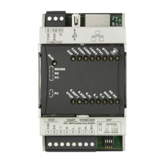
  • Seite 44: Bedeutung Der Statusleuchten (Led)

    Die LED zeigt an, dass ein oder mehrere Analogeingänge der E.AI PLCEXP-Busmodule außerhalb des Bereichs liegen Die leuchtende LED zeigt einen Software- / Hardwarefehler an den PLCEXP-Buserweiterungsmodulen an Die leuchtende LED zeigt an, dass sich in der SPS ein Software- / Hardwarefehler befindet. 44 - PL500-PL600-PL700 - Installationsanleitung...
  • Seite 45: Grafikschnittstelle - Webserver-Funktion

    SD-Speicher ausgeführt wird (SD auf EIN ) Grafikschnittstelle – Webserver-Funktion Der PLC PL500 in der Version PL500-335-1AD-WEB bietet dank der integrierten Movicon 11 CE-Laufzeit eine grafische Oberfläche und die Möglichkeit, Synoptiken zu entwickeln. Auf die grafische Oberfläche kann über jedes „VNC-Client“...
  • Seite 46 Notizen 46 - PL500-PL600-PL700 - Installationsanleitung...
  • Seite 48 Vor Verwendung des Gerätes sind die hier enthaltenen Informationen bezüglich Sicherheit und Einstellung aufmerksam zu lesen. Proc. Cont. Eq. E498498 PIXSYS s.r.l. www.pixsys.net sales@pixsys.net - support@pixsys.net online assistance: http://forum.pixsys.net via Po, 16 I-30030 Mellaredo di Pianiga, VENEZIA (IT) Tel +39 041 5190518 2300.10.257-RevD...

Diese Anleitung auch für:

Pl600Pl700

Inhaltsverzeichnis