Herunterladen Inhalt Inhalt Diese Seite drucken

Werbung

Verfügbare Sprachen

Verfügbare Sprachen

EDKLM3−XXX−001
.6a[
Global Drive
ELM3−030H004, ELM3−0140H010, ELM3−007H025,
ELM3−004H055
Motorfilter
Motor filter
Filtre moteur
Montageanleitung
Mounting Instructions
Instructions de montage
l

Werbung

Inhaltsverzeichnis
loading

Inhaltszusammenfassung für Lenze ELM3-030H004

  • Seite 1 EDKLM3−XXX−001 .6a[ Montageanleitung Mounting Instructions Instructions de montage Global Drive ELM3−030H004, ELM3−0140H010, ELM3−007H025, ELM3−004H055 Motorfilter Motor filter Filtre moteur...
  • Seite 2 Lesen Sie zuerst diese Anleitung und die Dokumentation zum Grundgerät, bevor Sie mit den Arbeiten beginnen! Beachten Sie die enthaltenen Sicherheitshinweise. Please read these instructions and the documentation of the standard device before you start working! Observe the safety instructions given therein! Lire le présent fascicule et la documentation relative à...
  • Seite 3 ELM3−001...
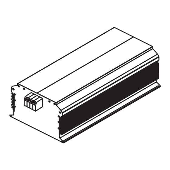
  • Seite 4 0Abb. 0Tab. 0 Lieferumfang Anzahl Beschreibung Filter Montageanleitung Elemente am Filter Position Beschreibung Anschlussklemmen Eingang (U, V, W, PE, +UG, −UG; bei einigen Typen: zusätzlich T1, T2) Anschlussklemmen Ausgang (U1, V1, W1, PE) Typenschild Gültigkeit Diese Anleitung ist gültig für ƒ...
  • Seite 5 Für Motorleitungen gilt die Einhaltung der EMV−Grenzwerte nur für die leitungsgebundene Störaussendung. ƒ beim Einsatz von Motoren, deren Isolationssysteme nicht für den Umrichterbetrieb geeignet sind. Bei Lenze−Motoren sind die Isolationen mit einer hohen thermischen Reserve aufgebaut. Beachten Sie: ƒ Der Betrieb ist nur zulässig mit einer U/f− oder U/f −Kennliniensteuerung und mit...
  • Seite 6: Dokumenthistorie

    Dokumenthistorie Materialnummer Version Beschreibung .6a[ 01/2014 TD15 Überarbeitung 13216458 11/2007 TD29 abgespaltene Neuauflage, EDKLM3−XXX−001 und EDKLM3−XXX−002 ersetzen EDKELM3223 (00466373) Tipp! Informationen und Hilfsmittel rund um die Lenze−Produkte finden Sie im Download−Bereich unter http://www.Lenze.com EDKLM3−XXX−001 DE/EN/FR 1.1...
  • Seite 7: Inhaltsverzeichnis

    Inhalt Sicherheitshinweise ..........Definition der verwendeten Hinweise .
  • Seite 8: Sicherheitshinweise

    Sicherheitshinweise Definition der verwendeten Hinweise Sicherheitshinweise Definition der verwendeten Hinweise Um auf Gefahren und wichtige Informationen hinzuweisen, werden in dieser Dokumenta- tion folgende Piktogramme und Signalwörter verwendet: Sicherheitshinweise Aufbau der Sicherheitshinweise: Gefahr! (kennzeichnet die Art und die Schwere der Gefahr) Hinweistext (beschreibt die Gefahr und gibt Hinweise, wie sie vermieden werden kann) Piktogramm und Signalwort...
  • Seite 9: Restgefahren

    Sicherheitshinweise Restgefahren Anwendungshinweise Piktogramm und Signalwort Bedeutung Wichtiger Hinweis für die störungsfreie Funktion Hinweis! Nützlicher Tipp für die einfache Handhabung Tipp! Verweis auf andere Dokumentation Restgefahren Gefahr! Gefährliche elektrische Spannung Alle Leistungsanschlüsse führen sowohl bei gestopptem Motor als auch bis zu 3 Minuten nach Netz−Ausschalten gefährliche elektrische Spannung.
  • Seite 10: Technische Daten

    Technische Daten Allgemeine Daten und Einsatzbedingungen Technische Daten Allgemeine Daten und Einsatzbedingungen Normen Konformität Niederspannungsrichtlinie (2006/95/EG) Schutz Schutzart EN 60529 IP 20 nicht im Anschlussbe- reich der Klemmen NEMA 250 Berührschutz nach Typ 1 Isolationsfestigkeit EN 61800−5−1 Überspannungskategorie III Reduzierung ab 2000 m: Überspannungskategorie II Ableitstrom EN 61800−5−1 >...
  • Seite 11 Technische Daten Allgemeine Daten und Einsatzbedingungen Montagebedingungen Montageort im Schaltschrank Montageposition möglichst nahe am Grundgerät Einbaulage senkrecht Einbaufreiräume oben und unten > 80 mm seitlich > 10 mm Anschlussleitungen « möglichst kurz, geschirmt Grundgerät Filter « abhängig von der Schaltfrequenz Filter Motor 4 kHz: <...
  • Seite 12: Bemessungsdaten

    Technische Daten Bemessungsdaten Bemessungsdaten Spannung Phasen max. Strom [A] Induktivität   [mH] bis +40 °C bis +55 °C ELM3−030H004 ELM3−014H010 ± 10 % ELM3−007H025 15.6 ELM3−004H055 34.4  Temperatur im Schaltschrank Schutz der Motorwicklung Begrenzung Motorüberspannung [kV] du/dt [V/ ELM3−030H004 ELM3−014H010 <...
  • Seite 13: Mechanische Daten

    Technische Daten Mechanische Daten Mechanische Daten Bauform 1 ELM3−003a Alle Maße in Millimeter. Maße [mm] Masse [kg] ELM3−030H004 ELM3−014H010 266.5 ELM3−007H025 EDKLM3−XXX−001 DE/EN/FR 1.1...
  • Seite 14 Technische Daten Mechanische Daten Bauform 2 6.5 (M6) ELM3−003b Alle Maße in Millimeter. Masse [kg] ELM3−004H055 EDKLM3−XXX−001 DE/EN/FR 1.1...
  • Seite 15: Mechanische Installation

    Mechanische Installation Wichtige Hinweise Mechanische Installation Wichtige Hinweise ƒ Der Montageort muss den in den Technischen Daten genannten Einsatzbedingungen immer entsprechen (^ 10). Ggf. zusätzliche Maßnahmen ergreifen. ƒ Die Montageplatte des Schaltschranks muss folgende Eigenschaften aufweisen: – elektrisch leitfähig – lackfrei ƒ...
  • Seite 16: Elektrische Installation

    Elektrische Installation Wichtige Hinweise Elektrische Installation Wichtige Hinweise ƒ Die Installation muss – den in den Technischen Daten genannten Einsatzbedingungen immer entsprechen (^ 10). – nach EN 60204−1 ausgeführt werden. ƒ Bei der Auswahl des Leitungstyps beachten: – Die verwendeten Leitungen müssen den geforderten Approbationen am Einsatzort entsprechen (z.
  • Seite 17: Anschlussdaten

    Elektrische Installation Anschlussdaten Anschlussdaten [Nm] [AWG] [mm] [lb−in] ELM3−030H004 0.6 ... 0.8 0.2 ... 4 0.25 ... 4 0.5 ... 1.5 24 ... 10 5.3 ... 7.1 ELM3−014H010 1.5 ... 1.8 ELM3−007H025 0.2 ... 6 0.25 ... 6 0.5 ... 4 24 ...
  • Seite 18: Montageschritte

    Elektrische Installation Montageschritte Montageschritte So schließen Sie das Filter an: 1. Schaltschrank spannungsfrei schalten und gegen Wiedereinschalten sichern. 2. Mindestens 3 Minuten warten, dann Spannungsfreiheit des Grundgerätes prüfen. 3. Filter−Eingangsleitung und Filter−Ausgangsleitung gemäß Anschlussplan verdrahten. – Anzugsmoment beachten. 4. DC−Zwischenkreisleitung (+UG/−UG) gemäß Anschlussplan verdrahten. –...
  • Seite 19 Elektrische Installation Montageschritte EDKLM3−XXX−001 DE/EN/FR 1.1...
  • Seite 20 0Fig. 0Tab. 0 Scope of supply Quantity Description Filter Mounting Instructions Elements on the filter Position Description Input terminals (U, V, W, PE, +UG, −UG; in some types also T1, T2) Output terminals (U1, V1, W1, PE) Nameplate Validity These instructions are valid for ƒ...
  • Seite 21 Motor cables must comply with EMC limit values only with regard to conducted interference emission. ƒ When operating motors whose insulation systems are not suitable for inverter operation. Lenze motors have insulations with greater thermal reserves. Please note: ƒ Operation is only permissible if a V/f or V/f characteristic control and a switching frequency of 4 ...
  • Seite 22: Document History

    Description .6a[ 01/2014 TD15 Revision 13216458 11/2007 TD29 Separate reprint, EDKELM3223 is replaced by EDKLM3−XXX−001 and EDKLM3−XXX−002 (00466373). Tip! Information and auxiliary devices related to the Lenze products can be found in the download area at http://www.Lenze.com EDKLM3−XXX−001 DE/EN/FR 1.1...
  • Seite 23 Contents Safety instructions ..........Definition of notes used .
  • Seite 24: Safety Instructions

    Safety instructions Definition of notes used Safety instructions Definition of notes used The following pictographs and signal words are used in this documentation to indicate dangers and important information: Safety instructions Structure of safety instructions: Danger! (characterises the type and severity of danger) Note (describes the danger and gives information about how to prevent dangerous situations)
  • Seite 25: Residual Hazards

    Safety instructions Residual hazards Application notes Pictograph and signal word Meaning Important note to ensure troublefree operation Note! Useful tip for simple handling Tip! Reference to another documentation Residual hazards Danger! Dangerous voltage All power connections carry dangerous voltages both if the motor is at standstill and after up to 3 minutes after mains switch off.
  • Seite 26: Technical Data

    Technical data General data and operating conditions Technical data General data and operating conditions Standards Conformity Low−voltage Directive (2006/95/EC) Protection Type of protection EN 60529 IP 20 Not in the wire range of NEMA 250 Protection against contact to the terminals type 1 Insulation resistance EN 61800−5−1...
  • Seite 27 Technical data General data and operating conditions Mounting conditions Mounting location In the control cabinet Mounting position As close as possible to the standard device Mounting position vertical Free spaces at the top and at the > 80 mm bottom to the sides >...
  • Seite 28: Rated Data

    Technical data Rated data Rated data Voltage Phases Max. current [A] Inductance Type up to +40 °C up to +55 °C [mH]   ELM3−030H004 ELM3−014H010 ± 10 % ELM3−007H025 15.6 ELM3−004H055 34.4  Temperature in the control cabinet Protection of the motor winding Limitation of the motor overvoltage [kV] Type...
  • Seite 29: Mechanical Data

    Technical data Mechanical data Mechanical data Design 1 ELM3−003a All dimensions in millimetres. Dimensions [mm] Mass Type [kg] ELM3−030H004 ELM3−014H010 266.5 ELM3−007H025 EDKLM3−XXX−001 DE/EN/FR 1.1...
  • Seite 30 Technical data Mechanical data Design 2 6.5 (M6) ELM3−003b All dimensions in millimetres. Mass Type [kg] ELM3−004H055 EDKLM3−XXX−001 DE/EN/FR 1.1...
  • Seite 31: Mechanical Installation

    Mechanical installation Important notes Mechanical installation Important notes ƒ The mounting location must always fulfill the operating conditions specified in the Technical data. (^ 26). If necessary, take additional measures. ƒ The mounting plate of the control cabinet must be: –...
  • Seite 32: Electrical Installation

    Electrical installation Important notes Electrical installation Important notes ƒ Installation must – always be in accordance with the operating conditions specified in the Technical data (^ 26). – be carried out to EN 60204−1. ƒ Please observe the following when selecting the cable type: –...
  • Seite 33: Connection Data

    Electrical installation Connection data Connection data [Nm] [AWG] [mm] [lb−in] ELM3−030H004 0.6 ... 0.8 0.2 ... 4 0.25 ... 4 0.5 ... 1.5 24 ... 10 5.3 ... 7.1 ELM3−014H010 1.5 ... 1.8 ELM3−007H025 0.2 ... 6 0.25 ... 6 0.5 ...
  • Seite 34: Mounting Steps

    Electrical installation Mounting steps Mounting steps How to connect the filter: 1. De−energise the control cabinet and fuse it against re−energisation. 2. Wait for at least 3 minutes before checking the standard device for isolation from supply. 3. Wire the filter input cables and the filter output cables according to the connection plan.
  • Seite 35 Electrical installation Mounting steps EDKLM3−XXX−001 DE/EN/FR 1.1...
  • Seite 36: Equipement Livré

    0Fig. 0Tab. 0 Equipement livré Nombre Description Filtre Instructions de montage Eléments du filtre Position Description Bornes d’entrée (U, V, W, PE, +UG, −UG ; sur certains types : également T1, T2) Bornes de sortie (U1, V1, W1, PE) Plaque signalétique Validité...
  • Seite 37 ƒ Utilisation de moteurs dotés de systèmes d’isolement inadaptés à un fonctionnement avec variateur. Sur les moteurs Lenze, les systèmes d’isolement disposent d’une réserve thermique importante. Noter les points suivants : ƒ...
  • Seite 38 Description .6a[ 01/2014 TD15 Edition revue 13216458 11/2007 TD29 Réédition segmentée, EDKLM3−XXX−001 et EDKLM3−XXX−002 remplacent EDKELM3223 (00466373) Conseil ! Toutes les informations relatives aux produits Lenze peuvent être téléchargées sur notre site à l’adresse suivante : http://www.Lenze.com EDKLM3−XXX−001 DE/EN/FR 1.1...
  • Seite 39 Sommaire Consignes de sécurité ..........Définition des conventions utilisées .
  • Seite 40: Consignes De Sécurité

    Consignes de sécurité Définition des conventions utilisées Consignes de sécurité Définition des conventions utilisées Pour indiquer des risques et des informations importantes, la présente documentation utilise les mots et pictogrammes suivants : Consignes de sécurité Présentation des consignes de sécurité Danger ! (Le pictogramme indique le type de risque.) Explication...
  • Seite 41: Remarque Importante

    Consignes de sécurité Dangers résiduels Consignes d’utilisation Pictogramme et mot associé Explication Remarque Remarque importante pour assurer un fonctionnement correct importante ! Conseil utile pour faciliter la mise en œuvre Conseil ! Renvoi à une autre documentation Dangers résiduels Danger ! Tension électrique dangereuse Une tension électrique dangereuse circule dans tous les raccordements de puissance, même à...
  • Seite 42 Consignes de sécurité Dangers résiduels Danger ! Tension électrique dangereuse Le courant de fuite vers la terre (PE) est > 3.5 mA CA ou > 10 mA CC. Risques encourus : Mort ou blessures graves en cas de contact accidentel avec l’appareil en ƒ...
  • Seite 43: Spécifications Techniques

    Spécifications techniques Caractéristiques générales et conditions d’utilisation Spécifications techniques Caractéristiques générales et conditions d’utilisation Normes Conformité Directive Basse Tension (2006/95/CE) Protection Indice de protection EN 60529 IP 20 Pas dans la zone de raccordement des NEMA 250 Protection contre contacts bornes accidentels selon type 1 Résistance d’isolement...
  • Seite 44 Spécifications techniques Caractéristiques générales et conditions d’utilisation Conditions de montage Lieu de montage Armoire électrique Position de montage Le plus près possible de l’appareil de base Orientation de Verticale montage Espaces de montage En haut et en bas > 80 mm Sur le côté...
  • Seite 45: Caractéristiques Assignées

    Spécifications techniques Caractéristiques assignées Caractéristiques assignées Tension Phases Courant max. [A] Inductance Type Jusqu’à +40 Jusqu’à +55 [mH]   °C °C ELM3−030H004 ELM3−014H010 ± 10 % ELM3−007H025 15.6 ELM3−004H055 34.4  Température dans l’armoire électrique Protection du bobinage moteur Limitation de la surtension du moteur [kV]...
  • Seite 46: Caractéristiques Mécaniques

    Spécifications techniques Caractéristiques mécaniques Caractéristiques mécaniques Forme de construction 1 ELM3−003a Cotes en [mm] Cotes [mm] Poids Type [kg] ELM3−030H004 ELM3−014H010 266.5 ELM3−007H025 EDKLM3−XXX−001 DE/EN/FR 1.1...
  • Seite 47 Spécifications techniques Caractéristiques mécaniques Forme de construction 2 6.5 (M6) ELM3−003b Cotes en [mm] Poids Type [kg] ELM3−004H055 EDKLM3−XXX−001 DE/EN/FR 1.1...
  • Seite 48: Installation Mécanique

    Installation mécanique Remarques importantes Installation mécanique Remarques importantes ƒ Le lieu de montage doit toujours respecter les conditions d’utilisation indiquées dans les spécifications techniques (^ 43). Si besoin est, prendre des mesures supplémentaires. ƒ La plaque de montage de l’armoire électrique doit être : –...
  • Seite 49: Installation Électrique

    Installation électrique Remarques importantes Installation électrique Remarques importantes ƒ L’installation doit – toujours respecter les conditions d’utilisation indiquées dans les spécifications techniques (^ 43) ; – répondre aux exigences de la norme EN 60204−1. ƒ Lors du choix du type de câble, tenir compte des points suivants : –...
  • Seite 50: Données De Raccordement

    Installation électrique Données de raccordement Données de raccordement [Nm] [AWG] [mm] [lb−in] ELM3−030H004 0.6 ... 0.8 0.2 ... 4 0.25 ... 4 0.5 ... 1.5 24 ... 10 5.3 ... 7.1 ELM3−014H010 1.5 ... 1.8 ELM3−007H025 0.2 ... 6 0.25 ... 6 0.5 ...
  • Seite 51: Opérations De Montage

    Installation électrique Opérations de montage Opérations de montage Pour raccorder le filtre, procéder comme suit : 1. Couper la tension dans l’armoire électrique et s’assurer que toute mise sous tension est exclue. 2. Attendre au moins 3 minutes puis s’assurer que l’appareil de base est hors tension. 3.
  • Seite 52 © 01/2014 Lenze Drives GmbH Service Lenze Service GmbH Postfach 10 13 52 Breslauer Straße 3 D−31763 Hameln D−32699 Extertal Germany Germany +49 5154 82−0 0080002446877 (24 h helpline) Ê Ê +49 5154 82−2800 +49 5154 82−1112 š š Lenze@Lenze.com Service@Lenze.com...

Diese Anleitung auch für:

Elm3-007h025Elm3-004h055Elm3-0140h010

Inhaltsverzeichnis