Velleman VM129 Anleitung
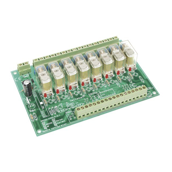
8-kanal-relaiskarte

Verwandte Anleitungen für Velleman VM129


Inhaltszusammenfassung für Velleman VM129
- Seite 24 Die Garantie kann nur beansprucht werden, wenn das Produtk mit der Originalrechnung abgegeben wird. Die Verpflichtungen der VELLEMAN COMPONENTS AG beschränken sich auf die Aufhebung der Fehler, oder, nach freier Wahl der VELLEMAN COMPONENTS AG , auf den Austausch oder die Reparation der fehlerhaften Teile.
-
Seite 25: Spezifikationen & Technische Daten
Spezifikationen und Technische kenndaten SPEZIFIKATIONEN & TECHNISCHE DATEN SPEZIFIKATIONEN : 8 hochwertige Relaiskontakte, 5A/230Vac max. Relaisausgänge sind über VDRs vor Überspannung geschützt LED-Bestätigung auf jedem Relaiskontakt 8 'drive'-Eingänge mit offenen Kollektoren oder normalen Schaltern zu verwenden Sehr geeignet zur Anwendung mit unserer Computer-Schnittstellenkarte VM110 oder unserem Infrarotempfänger VM122. TECHNISCHE DATEN : •... -
Seite 26: Speisung
Speisung SPEISUNG Wählen Sie einen geeigneten Ort für die Installation der Einheit. Wahrscheinlich werden Sie die Einheit in der Nähe eines Sicherungskastens MAINS installieren. Ein geeignetes Gehäuse für DIN-Schienenmontage ist lieferbar (Bestellnummer B8006). 1 x 12V / 500mA INPUT B8006 Optional Din rail enclosure Die Abbildungen auf den nächsten Seiten zeigen Anschlussbeispiele mit verschiedenen Eingangsmöglichkeiten. -
Seite 27: Eingangsanschluss-Beispiele
15-channel infrared receiver 'VM122' : Der Schaltplan (Abb. 1.0) zeigt wie Sie mögliche Relais Schnittstellenkarte VM122 VM122 VM129 anschließen können. Figure 1.0 1 x 12V / 500mA Die 15 Ausgänge dieses Moduls sind “open- RS232 collector"-Ausgänge. Das bedeutet, dass es... - Seite 28 Ausgangsanschluss - Beispiel USB Interface Board 'VM110' : Mit normalen Schaltern : RS232 RS232 VM129 V out VM110 V out +12V +12V PWM2 DAC2 PWM1 DAC1 CLAMP INPUTS INPUTS Figure 3.0 Figure 2.0...
-
Seite 29: Ausgangsanschluss-Beispiel
Ausgangsanschluss - Beispiel AUSGANGSANSCHLUSS-BEISPIEL 230V 230V... -
Seite 30: Sicherheits- Und Warnhinweise
Sicherheits– und Warnhinweise WARNUNG Lassen Sie Reparaturen durch Fachleute erfolgen Installieren Sie das Modul nicht in einer Umgebung mit stehendem oder fließendem Wasser oder in einer sehr feuchten Umgebung SICHERHEITSHINWEISE Gehen Sie behutsam mit dem Modul um. Es fallen lassen, kann die Leiterplatte und das Gehäuse beschädigen. Überschreiten Sie nie die in den technischen Daten erwähnten Eingangsgrößen. - Seite 38 Notes / Nota's / Notierungen / Cuenta...