Werbung
Quicklinks
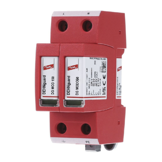
DEHNguard modular DG M TN 150 (FM)
II IEC 61643-11...
DE Einbauanleitung
2 EN 61643-11...
GB Installation instructions
IT Istruzioni di montaggio
FR Instructions de montage
NL Montagehandleiding
ES Instrucciones de montaje
PT Instruções de montagem
DK Monteringsvejledning
SE Monteringsanvisning
FI Asennusohje
GR Οδηγίε συναρ ολόγηση
PL Instrukcja montażu
1
CZ Montážní návod
TR Kurulum Talimatları
RU
0 mm
CN 安装说明
HU Szerelési útmutató
JP 設置説明書
DG M TN 150 (FM)
F1
L
N
F2
S
2
*)
*)
*) DG MOD 150
S
PE
3
S
4
LPZ 0
LPZ 0
LPZ 1
A
B
DEHNguard
DG M TN 150 (FM)
2 / II
DEHNguard
DG M TN 150 (FM)
3 / III
PZ 2
4 Nm
3
2
L'
N'
LPZ 2
LPZ 3
3 / III
1
U
/ Tol.: ±10%
N
U
C
max.
I
2
SCCR
I
max
ϑ
I
PE
IP
1
)
L x W x H
1
DEHNguard modular
DG M TN 150 (FM)
F1 ≤ 125 A gG
F1
F2
F1 > 125 A gG
F2
F2 ≤ 125 A gG
11 14
12
DG MOD 150
11 14
12
DG MOD 150
11 14
12
www.dehn-international.com
1686 / 07.19 / 3006406
DG M TN 150 (FM)
DG MOD 150
120 V (50/60 Hz)
150 V (50/60 Hz)
125 A gG
50 kA
rms
40 kA
-40°C ... + 80°C
5% ... 95%
< 0.4 mA
min.
□
L, N,PE
20
max.
□
L, N,PE
□
90 mm x 36 mm x 73 mm
DEHNguard modular
DG M TN 150 (FM)
F1
S
/ mm²
S
2
3
A gG
25
4
35
4
40
4
50
6
63
10
80
10
100
16
125
16
> 125
16
DEHNguard modular
DG M TN 150 FM
U
N
11
14
12
0.2 Nm
www.dehn.de
© COPYRIGHT 2019 DEHN SE + Co KG protected by ISO 16016
12 mm
12 mm
12 mm
1.5 mm²
25 mm²
35 mm²
16 mm² Cu
≥15.5 mm
/ mm²
S
/ mm²
F2
4
A gG
6
6
---
6
6
---
6
6
---
6
6
---
10
10
---
10
10
---
16
16
---
16
16
---
16
16
125
/ I
N
AC:
250 V / 0.5 A
DC:
250 V / 0.1 A
125 V / 0.2 A
75 V / 0.5 A
max. 1.5 mm²
Werbung

Verwandte Anleitungen für Dehn guardmodular DG M TN 150


Inhaltszusammenfassung für Dehn guardmodular DG M TN 150
- Seite 1 125 V / 0.2 A 75 V / 0.5 A 2 / II DEHNguard DG M TN 150 (FM) 3 / III 0.2 Nm max. 1.5 mm² 11 14 www.dehn.de www.dehn-international.com © COPYRIGHT 2019 DEHN SE + Co KG protected by ISO 16016...
- Seite 2 Use a local equipotential bonding bar if possible. For proper operation the SPD must be connected to a low impedance ground. Remote Contact Signaling: In case of a device with remote contact signaling make sure that the torque is as indicated in the technical data. The remote status indicator (SPDT contact) shall SPD classifiaction Type 4 Component Assemblies be connected to NEC Class 2 circuits only! Problem Diagnostics: If there should be any problem please contact your local DEHN representative.