Herunterladen Inhalt Inhalt Diese Seite drucken
RISCO Group EL-5829 Bedienungsanleitung

RISCO Group EL-5829 Bedienungsanleitung

2-wege funk-lcd-bedienteil mit lcd-display

Werbung

Verfügbare Sprachen
  • DE

Verfügbare Sprachen

2-Way Wireless
LCD Keypad
Model: EL-5829
Installation and User Guide

Werbung

Inhaltsverzeichnis
loading

Inhaltszusammenfassung für RISCO Group EL-5829

  • Seite 1 2-Way Wireless LCD Keypad Model: EL-5829 Installation and User Guide...
  • Seite 2 Language Page...
  • Seite 3: What's In The Box

    Installation Instructions 2. Installation Registration The EL-5829 keypad must identify itself to the system receiver. This is done by registering the keypad to the iConnect 2-Way, as follows. Set the system to Registration mode. Go to the main menu and select [9]>[1]>[3] (Programming >...
  • Seite 4: Wall Mounting

    Deleting a Keypad ➢ To delete a wireless keypad from the system: Set the system to Delete mode. Go to the main menu and select [9]>[1]>[3] (Programming > Devices > Keypads). Select a keypad (1 - 4). Select the Delete menu. Press >...
  • Seite 5 To mount the keypad: ➢ Release the mounting bracket. Attach the mounting bracket to the wall using the supplied screws (see figure 1). Mounting Mounting Mounting Mounting Mounting hole for tamper Figure 1 Attach the wireless keypad to the mounting bracket by sliding the keypad down onto the bracket‘s four hooks (see figure 2).
  • Seite 6 Figure 2 Attach the housing screw at the bottom of the front cover (see figure 3). Figure 3 Note: To use the back tamper, the back-tamper screw must be installed.
  • Seite 7 3. Main User Operations Control Keys Operation In Normal Operation mode: Used for Away (Full setting). In Normal Operation mode: Used for Stay arming (Part Setting). In Normal Operation mode: used to enter the menus with code. Long press: activates quick registration Used also to terminate commands and confirm data to be stored.
  • Seite 8: Emergency Keys

    Emergency Keys The following operations will send emergency notifications to the alarm monitoring station. Operation Pressing both keys simultaneously for at least two seconds activates a Fire alarm Pressing both keys simultaneously for at least two seconds activates an Emergency alarm Pressing both keys simultaneously for at least two seconds activates a Police (Panic) alarm.
  • Seite 9: Visual Indicators

    4. Visual Indicators The following visual indicators are displayed on the LCD panel: Icon Indication Operation System is operating properly from AC power and backup battery is in good condition Slow flash Control Panel/Keypad low battery Power Rapid flash Control Panel AC loss System trouble System is operating normally Trouble / Tamper...
  • Seite 10: Replacing Batteries

    5. Replacing Batteries When the batteries need to be replaced the indicator will flash. ➢ To replace the batteries: From the control panel, long press to enter replace battery mode. Remove the keypad from the wall. Open the battery compartment (see Figure 4). Figure 4 Pull out the batteries and replace them with new ones.
  • Seite 11 Figure 5 Close the battery compartment and put back the keypad to its place. 6. Keypad Settings Note: The following settings must be defined individually for each keypad connected to the system. ➢ To define keypad settings when idle follow this procedure: Press for five seconds until the Keypad Settings menu appears.
  • Seite 12 Press Press the keys to adjust the level settings. Press to save the adjustment. Press to exit the keypad settings.
  • Seite 13: Technical Specification

    E4US299KP0TA WL Shield KP 433MHz RED Compliance Statement Hereby, RISCO Group declares that this equipment is in compliance with the essential requirements and other relevant provisions of Directive 2014/53/EU. For the CE Declaration of Conformity please refer to our website:...
  • Seite 14: Contenu De L'emballage

    Instructions d'installation 2. Installation Enregistration Le clavier EL-5829 doit s’identifier sur le récepteur du système. Pour cela, il est nécessaire d'enregistrer le clavier sur le système bidirectionnel iConnect en procédant comme suit : Configurez le système sur le mode d’enregistrement.
  • Seite 15 Ouvrez le compartiment à piles et insérez les piles. Veillez à respecter les polarités. Lorsque l’indication « Enregistrer ? » s'affiche sur l’écran LCD du système de contrôle, appuyez sur « √ ». Suppression d’un clavier ➢ Pour supprimer un clavier sans fil du système : Configurez le mode de suppression sur le système.
  • Seite 16: Montage Mural

    Montage mural Une fois le clavier enregistré sur le système, fixez-le au mur à l'aide du support de montage fourni. Remarques : 1. Avant d'installer le clavier, vérifiez qu'il communique correctement avec le système. Pour ce faire, essayez d’armer le système à l'aide de l’une des touches d’armement du clavier sans fil (reportez-vous à...
  • Seite 17 Fixez le clavier sans fil au support de montage ; pour cela, insérez-le dans les quatre crochets du support (reportez-vous à la Figure 2). Crochet 1 de 4 Figure 2 Serrez la vis du boîtier au bas du cache avant (reportez-vous à la Figure 3). Figure 3 Remarque : pour utiliser la fonction d’autoprotection à...
  • Seite 18: Touches De Commande

    3. Opérations principales de l’utilisateur Touches de commande Touche Opération En mode de fonctionnement normal : cette touche permet de sélectionner le mode Armer totalement. En mode de fonctionnement normal : cette touche permet de sélectionner le mode Armer partiellement. En mode de fonctionnement normal : cette touche permet d'accéder aux menus avec un code.
  • Seite 19: Touches D'urgence

    Touche Opération Dans le menu Fonctions de l’utilisateur, elle permet de revenir à l’étape précédente dans le menu. Un appui long sur cette touche permet d’activer le mode de suppression rapide. Touches d'urgence Les procédures suivantes permettent d'envoyer des notifications d'urgence au centre de télésurveillance.
  • Seite 20: Touches De Fonction

    Touche Opération Appuyez longuement sur la touche droite pour activer le mode de remplacement des piles. Touches de fonction Touche Opération Touches numériques permettant de saisir des codes numériques (armement, désarmement ou activation de fonctions spécifiques. 4. Indicateurs visuels Les indicateurs visuels suivants sont affichés sur l'écran LCD : Icône Indication Opération...
  • Seite 21 Allumé Erreur système. Éteint Le système fonctionne normalement. Problème / Autoprotection Clignotement La zone, le clavier ou le module externe rapide a été autoprotégé. Allumé Le système est prêt pour l’armement. Éteint système n’est prêt pour Prêt l’armement. Allumé Le système est en mode Armer totalement, Armer partiellement ou Armer le périmètre.
  • Seite 22: Remplacement Des Piles

    5. Remplacement des piles Lorsqu’il est nécessaire de remplacer les piles, le témoin clignote. Pour remplacer les piles : ➢ Sur la centrale, appuyez longuement sur pour accéder au mode de remplacement des piles. Retirez le clavier du mur. Ouvrez le compartiment à piles (reportez-vous à la Figure 4). Figure 4 Retirez les piles et remplacez-les par des piles neuves.
  • Seite 23: Configuration Du Clavier

    Figure 5 Fermez le compartiment à piles et remettez le clavier en place. 6. Configuration du Clavier Remarque : vous devez définir individuellement les paramètres suivants pour chaque clavier connecté au système. Pour configurer le clavier lorsqu'il est inactif, procédez comme ➢...
  • Seite 24 Luminosité Contraste Volume du buzzer du clavier Appuyez sur Appuyez sur les touches pour régler les niveaux. Appuyez sur la touche pour enregistrer les valeurs définies. Appuyez sur la touche pour quitter la configuration du clavier.
  • Seite 25: Caractéristiques Techniques

    Clavier sans fil 433 MHz Déclaration de Conformité RED Par la présente, RISCO Group déclare que cet équipement est conforme aux exigences essentielles et autres dispositions pertinentes de la directive 2014/53/EU. Pour la déclaration de conformité CE, consultez notre site web à l'adresse...
  • Seite 26: Contenido De La Caja

    1. Descripción El EL-5829 es un teclado inalámbrico bidireccional con pantalla LCD que se utiliza para programar y operar de forma remota los sistemas bidireccionales iConnect. La funcionalidad del teclado es idéntica a la de los botones del panel frontal del iConnect bidireccional.
  • Seite 27 En cuanto aparezca el mensaje '¿Guardar?' en la pantalla LCD del sistema de control, presione '√'. Eliminación de un teclado ➢ Para eliminar un teclado inalámbrico del sistema: Ajuste el sistema en modo Eliminar. Vaya al menú principal y seleccione [9]>[1]>[3] (Programación >...
  • Seite 28 Para montar el teclado: ➢ Quite el soporte de montaje. Coloque el soporte de montaje en la pared usando los tornillos suministrados (ver Figura 1). Montaje Montaje Montaje Montaje Orifcio de montaje pour para tamper Figura 1 Coloque el teclado inalámbrico en el soporte de montaje deslizando el teclado en los cuatro ganchos del soporte (ver Figura 2).
  • Seite 29 Gancho 1 de 4 Figura 2 Coloque el tornillo de la caja en la parte inferior de la cubierta frontal (ver Figura 3). Figura 3 NOTA: Para poder usar el tamper posterior, debe estar colocado el tornillo del tamper.
  • Seite 30 3. Operaciones principales del usuario Botones de control Botón Operación En el modo Normal: se usa para Armar Todo. En el modo Normal: se usa para Armado Parcial. En el modo Operación Normal: se usa para acceder a los menús con código.
  • Seite 31 Botón Operación En el menú de funciones del usuario: se usa para retroceder un paso en el menú. Pulsación larga: activa el modo de eliminación rápida. Botones de emergencia Las siguientes acciones enviarán notificaciones de emergencia a la central receptora de alarmas.
  • Seite 32: Botones De Función

    Botones de función Botón Operación Botones numéricos que se usan para introducir códigos numéricos (para armar, desarmar o activar funciones específicas). 4. Indicadores visuales Los siguientes indicadores visuales se muestran en el panel LCD. Icono Indicación Operación Encendido El sistema funciona correctamente con corriente de CA y las pilas de respaldo están en buen estado Parpadeo...
  • Seite 33 Icono Indicación Operación Encendido El sistema está listo para el armado Apagado El sistema no está listo para el armado Listo Encendido El sistema está ajustado en Armado Total, Armado Parcial, Armado o modo de Armado Perimetral Apagado El sistema está desarmado Armado/Alarma Parpadeo Problema con la alarma...
  • Seite 34: Reemplazo De Las Pilas

    5. Reemplazo de las pilas Cuando sea necesario reemplazar las pilas, el indicador parpadeará. ➢ Para reemplazar las pilas: Desde el panel de control, realice una pulsación larga para acceder al modo de reemplazo de las pilas. Quite el teclado de la pared. Abra el compartimento de las pilas (ver Figura 4).
  • Seite 35 Figura 5 Cierre el compartimento de las pilas y vuelva a colocar el teclado en su sitio. 6. Ajustes del teclado Nota: es preciso definir los siguientes ajustes de forma individual en cada teclado conectado al sistema. Para definir los ajustes del teclado mientras está inactivo, siga ➢...
  • Seite 36 Brillo Contraste Volumen del zumbador del teclado Presione Presione los botones para ajustar los niveles Presione para guardar el ajuste Presione para salir del menú Ajustes del teclado.
  • Seite 37: Especificaciones Técnicas

    Protector KP inalámbrico de 433 MHz Cómo funcionaDeclaración de Cumplimiento de Por la presente, RISCO Group declara que su equipo cumple los requisitos esenciales y otras disposiciones relevantes de la Directiva 2014/53/UE. Para ver la Declaración de Conformidad de la CE, vaya a nuestro sitio web:...
  • Seite 38: Installation

    1. Beschreibung Das EL-5829 ist ein 2-Wege Funk-LCD-Bedienteil mit LCD-Display zur Fernprogrammierung und Bedienung der iConnect 2-Wege-Systeme. Die Funktionalität des Bedienteils ist identisch mit den Tasten auf der iConnect 2- Wege-Frontblende. Hinweis: Der Programmiermodus kann entweder über ein Bedienteil oder über die Hauptzentrale eingerichtet werden, jedoch nicht gleichzeitig.
  • Seite 39 Sobald „Save? (Speichern?)“ auf dem LCD-Bildschirm der Zentrale erscheint, drücken Sie „√“. Bedienteil löschen ➢ Löschen eines Funk-Bedienteils aus dem System: Gehen Sie zum Hauptmenü und wählen Sie. [9]>[1]>[3](Programming > Devices > Keypads (Programmierung > Module > Bedienteile Wählen Sie ein Bedienteil (1-4). Wählen Sie das Löschmenü.
  • Seite 40: Bedienfeld Montieren

    Bedienfeld montieren: ➢ Lösen Sie den Montagehalter. Montieren Sie den Montagehalter mit den mitgelieferten Schrauben an der Wand (siehe Abbildung 1). Montage Montage Montage Montage Befesigungsloch für Sabotageschutz Abbildung 1 Befestigen Sie das Funk-Bedienteil an dem Montagehalter, indem Sie das Bedienteil nach unten auf die vier Haken des Montagehalters schieben (siehe Abbildung 2).
  • Seite 41 Haken (1 von 4) Abbildung 2 Befestigen Sie die Gehäuseschraube an der Unterseite der Frontabdeckung an (siehe Abbildung 3). Abbildung 3 Hinweis: Um den hinteren Sabotageschutz zu verwenden, muss die Schraube für den hinteren Sabotageschutz installiert werden.
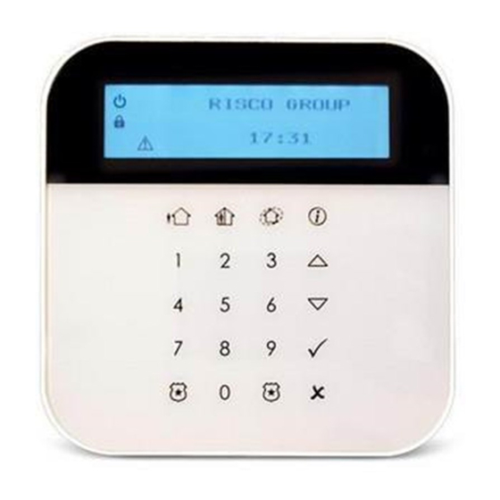
  • Seite 42 3. Hauptbenutzer-Operationen Steuertasten Taste Betrieb Im Normalbetrieb: Wird für „Abwesend“ Aktivieren verwendet (volle Scharfschaltung). Im Normalbetrieb: Wird für „Anwesend“ Aktivieren verwendet (Teilscharf). Im Normalbetriebsmodus: Wird zum Aufrufen der Menüs mit Code verwendet. Langer Tastendruck: Aktiviert die Schnellregistrierung Wird auch verwendet, um Befehle zu beenden und zu speichernde Daten zu bestätigen.
  • Seite 43 Notfalltasten Die folgenden Operationen senden Notfallbenachrichtigungen an die Alarm- Notrufzentrale. Taste Betrieb Durch gleichzeitiges Drücken beider Tasten für mindestens zwei Sekunden wird ein Feueralarm ausgelöst Durch gleichzeitiges Drücken beider Tasten für mindestens zwei Sekunden wird ein Notfallalarm aktiviert Durch gleichzeitiges Drücken beider Tasten für mindestens zwei Sekunden wird ein Polizei-(Panik-) Alarm ausgelöst.
  • Seite 44: Visuelle Anzeigen

    Funktionstasten Taste Betrieb Numerische Tasten dienen Eingabe numerischen Codes (Aktivierung, Deaktivierung oder zur Aktivierung bestimmter Funktionen). 4. Visuelle Anzeigen Die folgenden visuellen Anzeigen werden auf dem LCD-Bildschirm angezeigt: Symbol Anzeige Betrieb Das System arbeitet ordnungsgemäß mit Netzversorgung und die Backup- Batterie ist in gutem Zustand Blinkt Zentrale/Bedienteil schwache Batterie...
  • Seite 45 Symbol Anzeige Betrieb System ist für die Scharfschaltung bereit System ist für Scharfschaltung nicht Bereit bereit Das System ist in den vollständigen, teilweisen oder Perimeter-Scharfmodus eingestellt Einstellung/ System ist unscharf Alarm Blinkt schnell Alarmzustand...
  • Seite 46: Batterien Wechseln

    5. Batterien wechseln Wenn die Batterien gewechselt werden müssen, blinkt die Anzeige Ersetzen der Batterien: ➢ Drücken Sie auf dem Bedienfeld lange auf , um den Batteriewechselmodus aufzurufen. Entfernen Sie das Bedienteil von der Wand. Öffnen Sie das Batteriefach (siehe Abbildung 4). Abbildung 4 Nehmen Sie die Batterien heraus und ersetzen Sie sie durch neue.
  • Seite 47: Bedienteil-Einstellungen

    Abbildung 5 Schließen Sie das Batteriefach und setzen Sie das Bedienteil wieder an seinen Platz zurück. 6. Bedienteil-Einstellungen Hinweis: Die folgenden Einstellungen müssen für jedes an das System angeschlossene Bedienteil einzeln festgelegt werden. ➢ Gehen Sie wie folgt vor, um die Bedienteil-Einstellungen im Ruhezustand festzulegen: Drücken Sie fünf Sekunden lang, bis das Bedienteil-Einstellungen-...
  • Seite 48 Helligkeit Kontrast Lautstärke des Bedienteil-Summers Drücken Sie Passen Sie mit den Tasten die Pegeleinstellungen an. Drücken Sie , um die Anpassung zu speichern. Drücken Sie , um die Bedienteil Einstellungen zu verlassen.
  • Seite 49: Technische Daten

    7. Technische Daten Leistung 4 x CR123 Lithium Batterien 50 μA (Standby)/bis zu 100 mA Stromaufnahme (Übertragung) Typische Batterielebensdauer 3 Jahre Ausgangsleistung 10 mW Betriebstemperatur -10 - 55 °C Lagertemperatur -20 - 60 °C Luftfeuchtigkeit Bis zu 75 % 214 x 110 x 35 mm (HxBxT) Abmessungen cremefarben Farbe...
  • Seite 50 1. Beskrivelse EL-5829 er et 2-vejs trådløst tastatur med LCD-display, der anvendes til fjernprogrammering og -betjening af iConnect 2-vejssystemer. Tastaturets funktionalitet er identisk med den, der findes på iConnect 2-vejs frontpanel. Bemærk: Programmeringstilstand kan aktiveres enten fra et tastatur eller fra hovedpanelet, men ikke samtidig.
  • Seite 51 Sletning af et tastatur ➢ Hvis du vil slette et trådløst tastatur fra systemet: Sæt systemet i slettetilstand. Gå ind i hovedmenuen, og vælg [9]>[1]>[3] (Programming > Devices > Keypads (programmering > enheder > tastaturer)). Vælg et tastatur (1 – 4). Vælg menuen til sletning.
  • Seite 52 Sådan monteres tastaturet: ➢ Udløs monteringsbeslaget. Fastgør monteringsbeslaget til væggen med de medfølgende skruer (se Fig. 1). Ophængning Ophængning Ophængning Ophængning Hul til sabotagekontakt Fig. 1 Fastgør det trådløse tastatur til monteringsbeslaget ved at skyde det ned over de fire kroge på monteringsbeslaget (se Fig. 2).
  • Seite 53 Krog (1 af 4) Fig. 2 Fastgør skruen til huset i bunden af frontdækslet (se Fig. 3). Fig. 3 Bemærk : Hvis du vil anvende sabotagekontakt, skal sabotageskruen sættes i på bagsiden.
  • Seite 54 3. Grundlæggende brugerbetjening Kontroltaster Tast Betjening I normal driftstilstand: Anvendes til Fuld tilkobling (Fuld tilkobling). I normal driftstilstand: Anvendes til Hjemme tilkobling (Delvis tilkobling). I normal driftstilstand: anvendes til åbning af menuer med kode. Hold inde: aktiverer hurtigregistrering. Bruges også til at afslutte kommandoer og bekræfte, at data skal gemmes. I normal driftstilstand: Bruges til skaltilkobling.
  • Seite 55 Nødtaster Følgende handlinger sender beskeder om nødopkald til kontrolcentralen. Tast Betjening Hvis begge taster holdes inde i mindst to sekunder, aktiveres en Brandalarm. Hvis begge taster holdes inde i mindst to sekunder, aktiveres en Nødalarm. Hvis begge taster holdes inde i mindst to sekunder, aktiveres en Panikalarm (der sendes til kontrolcentralen).
  • Seite 56 Funktionstaster Tast Betjening Numeriske taster anvendes til indtastning af talkoder (tilkobling, frakobling eller aktivering af specifikke funktioner). 4. Visuelle indikatorer Følgende visuelle indikatorer vises på LCD-displayet: Ikon Visning Betjening Lyser Systemet kører normalt på strøm fra lysnettet, og backupbatteriet er i god stand Blinker Lavt batteriniveau i kontrolpanel/tastatur langsomt...
  • Seite 57 Ikon Visning Betjening Lyser Systemet er klar til indstilling Slukket Systemet er ikke klar til indstilling/tilkobling Klar Lyser Systemet er indstillet til fuld tilkobling, hjemmetilkobling eller skaltilkobling Slukket Systemet er ikke indstillet Indstil/alarm Blinker Alarmtilstand hurtigt...
  • Seite 58: Udskiftning Af Batterier

    5. Udskiftning af batterier Når batterierne trænger til udskiftning, blinker indikatoren ➢ Sådan udskiftes batterierne: Hold inde på kontrolpanelet for at aktivere batteriudskiftningstilstand. Tag tastaturet ned fra væggen. Åbn batterirummet (se Fig. 4). Fig. 4 Tag batterierne ud, og erstat dem med nye. Vær opmærksom på polariteten, når du lægger de nye batterier i (se Fig.
  • Seite 59 Fig. 5 Luk batterirummet, og sæt tastaturet tilbage på plads. 6. Tastaturindstillinger Bemærk: Følgende indstillinger skal defineres individuelt for hvert enkelt tastatur, der er forbundet til systemet. To Tastaturindstillingerne defineres ved at følge nedenstående ➢ procedure, mens tastaturet ikke er aktivt: Hold inde i fem sekunder, indtil menuen til opsætning af tastatur vises på...
  • Seite 60 Lysstyrke Kontrast Lydstyrke for tastatur Tryk Tryk på for at justere indstillingerne for niveau. Tryk på for at gemme ændringerne. Tryk på for at lukke tastaturindstillingerne.
  • Seite 61: Tekniske Specifikationer

    E4US299KP0TA WL Shield KP 433MHz Erklæring om overholdelse af RED-direktivet Hermed erklærer RISCO Group, at dette udstyr er i overensstemmelse med de relevante krav og andre bestemmelser i direktiv 2014/53/EU. EU- overensstemmelseserklæringens fulde tekst kan findes på vores website: www.riscogroup.com...
  • Seite 62 Standard Limited Product Warranty (“Limited Warranty”) RISCO Ltd. (“RISCO") guarantee RISCO’s hardware products (“Products”) to be free from defects in materials and workmanship when used and stored under normal conditions and in accordance with the instructions for use supplied by RISCO, for a period of (i) 24 months from the date of delivery of the Product (the “Warranty Period”).
  • Seite 63 above are not met (including, but not limited to, full payment by customer for the Product and a proven weekly testing and examination of the Product functionality); (ii) if the Products or any part or component thereof: (a) have been subjected to improper operation or installation; (b) have been subject to neglect, abuse, willful damage, abnormal working conditions, failure to follow RISCO’s instructions (whether oral or in writing);...
  • Seite 64 WARNING: This product should be tested at least once a week. CAUTION: Risk of explosion if battery is replaced by an incorrect type. Dispose of used batteries according to local regulations. Contacting RISCO Group International Headquarters: United Kingdom RISCO Group Tel: +44 (0)161-655-5500 14 Hachoma St., 75655...

Inhaltsverzeichnis