Werbung
Quicklinks
RT- ...
Elektromechanischer Raumtemperaturregler im Flächenschalterrahmen
Sicherheitshinweis!
Dieses Gerät darf nur durch eine Elektrofachkraft geöffnet und gemäß dem entsprechenden
Schaltbild im Gehäusedeckel / auf dem Gehäuse / in der Bedienungsanleitung installiert
werden. Dabei sind die bestehenden Sicherheitsvorschriften zu beachten. Nach der Instal-
lation ist der Betreiber, durch die ausführende Installationsfirma, in die Funktion und Bedie-
nung der Regelung einzuweisen. Die Bedienungsanleitung muss für Bedien- und Wartungs-
personal an frei zugänglicher Stelle aufbewahrt werden.
1. Anwendung
Dieser Raumtemperaturregler wurde speziell für die Regelung oder Überwachung von
Temperaturen in Büros, Wohnräumen und Hotels entwickelt und ist geeignet für alle
Heizungsarten. Bei elektrischen Fußbodenheizungen ist darauf zu achten, dass die Leistung
der Heizung auch bei Dauerbetrieb den Estrich nicht überhitzen kann. Bei Warmwasser-
heizungen sind auf den Heizausgang max. 10 Ventilantriebe anzuschließen. Bei Warmwas-
serheizungen mit stromlos offenen Ventilen sind max. 5 Ventilantriebe an den Kühlausgang
anzuschließen. Im Kühlfall sind max. 5 stromlos geschlossenen Ventile auf den Kühlaus-
gang oder max.10 stromlos offene Ventile auf den Heizausgang anzuschließen. Gegebenen-
falls benötigte Temperaturbegrenzungen müssen zusätzlich installiert werden. Für andere,
vom Hersteller nicht vorherzusehende Einsatzgebiete, sind die dort gültigen Sicherheitsvor-
schriften zu beachten. Eignung hierfür siehe Punkt 7. Gewährleistung.
2. Funktionen
Der Raumtemperaturregler erfasst mit einem innenliegenden Bimetallfühler die Raumtem-
peratur und regelt entsprechend dem eingestellten Sollwert. Die einzelnen Reglertypen
unterscheiden sich durch die Ausstattung und Funktionalität. Hierzu Punkt 6. beachten.
2.1 Thermische Rückführung
Da während des Heiz- oder Kühlvorgangs der Regler die Raumtemperatur erst relativ spät
erfasst, wird mittels einer thermischen Rückführung der Regler rechtzeitig zum Ausschal-
ten angeregt und so eine sehr genaue Schaltdifferenz erreicht.
2.2 Bereichseinengung
Mittels der sich unter dem Knopf befindlichen Einstellfahnen kann der Einstellbereich
mechanisch begrenzt werden. (siehe Punkt 3.).
2.3 ECO-Betrieb (Nachtabsenkung)
Bei Reglern mit ECO-Betrieb (Uhrensymbol im Anschluss-Schaltbild) wird bei Beschalten
der Klemme
mit Phase der Betriebsspannung auf eine um ca. 4K geringere Temperatur
geregelt.
3. Installation / Montage
Je nach Gerätetyp oder Verpackungsgröße, wird das Gerät entweder geschlossen oder der
schnelleren Montage wegen geöffnet ausgeliefert. Das Gerät mit dem 50 x 50 mm Gehäu-
sedeckel ist mittels Zwischenrahmen der Schalterhersteller nach DIN 49075 in nahezu alle
Schalterprogramme integrierbar. Das Gerät mit dem 55 x 55 mm Gehäusedeckel ist eben-
falls für diverse Schalterprogramme geeignet. Bei Mehrfachrahmen ist der Regler immer an
unterster Stelle zu montieren. Der Regler ist zur Montage in die UP-Dose bestimmt und
darf nicht direkt Wärme- oder Kältequellen ausgesetzt werden. Es ist darauf zu achten,
dass der Regler auch rückseitig keiner Fremderwärmung oder -kühlung, z.B. bei Hohlwän-
den durch Zugluft oder Steigleitungen ausgesetzt wird.
Zum Öffnen des Reglers ist die Schraube nach Abziehen des Einstellknopfes zu lösen und
die Reglerkappe inklusive Rahmen abzunehmen. Nach elektrischem Anschluss und Mon-
tage in die UP-Dose, ist der Regler in umgekehrter Reihenfolge wieder zu schließen.
Um den Einstellbereich Einzuengen, wird der sich unter dem Einstellknopf befindliche Stift
abgezogen und die Einstellfahnen verstellt (rot für maximal und blau für minimal mögliche
Einstellung). Anschließend wird der Stift wieder eingesteckt und somit die Begrenzungen
arretiert.
Einstellfahne für
minimalen
Temperaturwert
Stand
09.2008 (EA08/146) JD
Flush framed electromechanical room controller
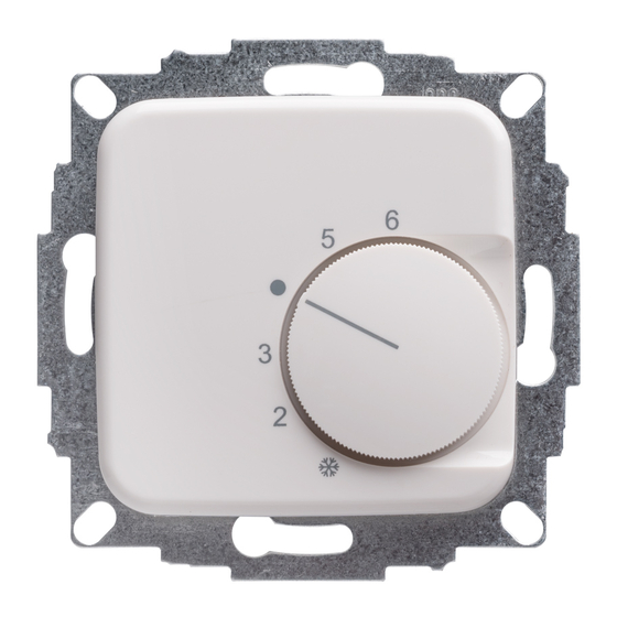
Regler 50 x 50 mit Beispiel-Rahmen
und Zwischenrahmen
Controller (50 x 50) with sample
frame and intermediate frame
Einstellfahne für
maximalen
Temperaturwert
Safety information!
D
No
persons other than expert electricians only must open this device in due compliance
with the wiring diagram shown in the housing cover / on the housing / represented in the
corresponding operating instructions. All expert electricians committed to the execution of
any such works must comply with the relevant safety regulations currently operative and in
force. The company charged with the installation of the device must, after the completion
of the installation works, instruct the user of the control system into its functions and in
how to operate it correctly. These operating instructions must be kept at a place that can be
accessed freely by the operating and/or servicing personnel in charge.
1. Application
This temperature controller has been specially devised for the control and supervision of
temperatures in offices, living spaces and hotels and is suited for the control of all types of
heating systems. With electric floor heating systems care must be taken to ensure that the
performance of the controlled system cannot, even if the system is operated continuously,
result in an overheating of the pavement. With hot water heating systems, no more than 10
valve drives must be connected to the heating output. With hot water heating systems with
normally closed valves, no more than 5 valve drives must be connected to the cooling
output. With water cooling systems, no more than 5 normally closed valves must be
connected to the cooling output and no more than 10 normally closed valves to the heating
output. Where applicable, temperature limiters need to be installed in addition. Regarding
other applications not to be foreseen by the manufacturer of this device, the safety
standards these applications need to be followed and adhered to. Regarding the aptitude of
the device for any such application, please refer to section 7. herein (Warranty).
2. Functional description
The room temperature controller described herein is equipped with an internal bimetal
sensor that captures the currently existing room temperature. The device controls the
related heating or cooling system in accordance with the adjusted set value. The different
controller models vary by their equipment and the functionalities they include. Regarding
thereto, please pay regard to section 6.
2.1 Thermal recirculation
As, during the heating and/or cooling procedure, the controller usually captures the actually
prevailing room temperature at a rather late point, a thermal recirculation has been realised
with the device that enables to deactivate it early enough with the consequence that a very
precise switching difference can be attained.
2.2 Suppression of the setting range
The setting elements (pins) located underneath of the knob enable to delimit the setting
range mechanically (see section 3.).
2.3 ECO mode (night temperature decrease mode)
With all controller models that enable to operate in ECO mode (indicated by the clock
symbol shown in the connection diagram), the room temperature is decreased by approx.
4K when connecting the operating voltage phase to the terminal
3. Mounting / Installation
The device is, depending on the type version of the device or size of the package used for
it, either delivered in closed or, in order to facilitate its fast installation, also in opened con-
dition. The device suits for the integration into almost all DIN 49075 compliant intermediate
frames that form part of the different frame lines offered by different producers. This is why
the device is, depending on the order specifications, delivered either with or without a
genuine ALRE intermediate frame. If using multiple frames, the controller must always be
mounted in the lowest position. The controller is determined for installation on an UP box
and must not be exposed to any heat or cold sources whatsoever. Also care must be taken
to ensure that it is not exposed to the influence of heat or cold sources that warm or cool
the device at its back (through air flows in cavity walls or the temperatures radiated by
ascending pipelines, f. ex.).
To open the controller, remove the adjusting knob first, then loosen the screw and remove
the controller cap. After its electrical connection and installation in the UP box, the closing
of the controller takes place in inverse order.
The setting pins located underneath of the adjusting knob enable to delimit the setting range
of the controller mechanically. To enable this, the adjusting knob must be removed by
pulling it off and, after the adjustment of the related pins (end stops, red for max. and blue
for min. setting) be put on again in
order to lock the limitations.
Setting pin for
minimum
temperature
limitation
GB
.
Regler 55 x 55 mit Beispiel-
Rahmen
Controller (55 x 55) with
sample frame
Setting pin for
maximum
temperature
limitation
4 12 616 05
Werbung

Inhaltszusammenfassung für Halmburger RT Serie
- Seite 1 RT- … Elektromechanischer Raumtemperaturregler im Flächenschalterrahmen Flush framed electromechanical room controller Sicherheitshinweis! Safety information! Dieses Gerät darf nur durch eine Elektrofachkraft geöffnet und gemäß dem entsprechenden persons other than expert electricians only must open this device in due compliance Schaltbild im Gehäusedeckel / auf dem Gehäuse / in der Bedienungsanleitung installiert with the wiring diagram shown in the housing cover / on the housing / represented in the werden.
- Seite 2 We refuse to grant any warranty with regard thereto. Subject to change without notice. Halmburger GmbH – Wasserburger Straße 8 – 84427 Sankt Wolfgang/Obb. – Tel.: 0 80 85/1879- 0 – Fax: 0 80 85/1879 -79...