Inhaltsverzeichnis
Werbung
Verfügbare Sprachen
Verfügbare Sprachen
Quicklinks
Werbung
Kapitel
Inhaltsverzeichnis

Verwandte Anleitungen für ifi SAM80 serie

Inhaltszusammenfassung für ifi SAM80 serie
- Seite 1 SAM80 M A N U A L E D ' U S O E M A N U T E N Z I O N E OPER ATION AN D MAINTENANCE MANUAL B E N U T Z E R H A N D - U N D WA R T U N G S B U C H MANUEL D’...
- Seite 2 INDICE / INDEX / INHALTS-VERZEICHNIS / SOMMAIRE / SUMARIO ITALIANO ......................... 3 ENGLISH ........................ 33 DEUTCH ......................... 63 FRANÇAIS ......................93 ESPAÑOL ......................123 SCHEMI ELETTRICI/ELECTRICAL DIAGRAMS/SCHALTSCHEMEN /SCHEMAS ELECTRIQUES/ESQUEMAS ELÉCRICOS ............153...
-
Seite 3: Inhaltsverzeichnis
Sommario INTRODUZIONE ............................. 4 1 SPECIFICHE TECNICHE ........................5 1.1 DESCRIZIONE DELLA VETRINA ....................... 5 1.1.1 STRUTTURA ............................ 5 1.1.2 UNITA’ REFRIGERANTE ......................... 5 1.2 MODELLI ............................. 5 1.3 IDENTIFICAZIONE ..........................6 1.4 NORME APPLICATE ........................... 6 1.5 CARATTERISTICHE TECNICHE ......................6 1.6 DIMENSIONI DI INGOMBRO E PESI .................... -
Seite 4: Introduzione
INTRODUZIONE Gentile cliente, Questo libretto ha lo scopo di illustrare l'uso e la manutenzione della vetrina e l'operatore ha il dovere e la responsabilità di seguirlo. IMPORTANTE! - Quanto descritto in questo manuale riguarda la vostra sicurezza. - Il Costruttore declina ogni responsabilità da un uso non previsto o contemplato nel presente manuale. -
Seite 5: Specifiche Tecniche
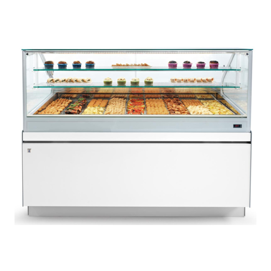
1 SPECIFICHE TECNICHE 1.1 DESCRIZIONE DELLA VETRINA E' essenzialmente costituita da due sezioni: 1.1.1 STRUTTURA La struttura portante è costituita da un telaio inferiore il basso in lamiera contenente l’unità refrigerante. Sopra di essa è posizionata la vasca monoblocco merce, sulla quale vengono fissate le superfici La restante parte della vetrina è... -
Seite 6: Identificazione
1.3 IDENTIFICAZIONE Fig.2 Per qualsiasi comunicazione con il produttore o con centri assistenza citare sempre il NUMERO DI MATRICOLA della vetrina, che è apposto sulla targhetta (Fig.2). 1.4 NORME APPLICATE La vetrina risponde alleseguenti norme: - 2006/95/CE (Direttiva Bassa Tensione) - 97/23/CE (Apparecchiature a pressione) - 2004/108/CE (Compatibilità... - Seite 7 SAM80 PASTICCERIA MENSOLE REFRIGERATE TAB. 1 Unità di SAM80 SAM80 SAM80 CARATTERISTICHE Misura 1125 1625 2125 1717/8.7 2081/10.8 2236/10.5 Potenza Assorbita 230V / 1 / 50 Hz 30°C/55% 30°C/55% 30°C/55% Classe Climatica °C/UR -10°C -10°C -10°C Temperatura di Espansione °C +45°C +45°C +45°C...
- Seite 8 SAM80 PRALINERIA TAB. 1 Unità di SAM80 SAM80 SAM80 CARATTERISTICHE Misura 1125 1625 2125 Potenza Assorbita 230V / 1 / 50 Hz 2320/11.3 3224/15.8 3421/15.7 35°C/60% 35°C/60% 35°C/60% Classe Climatica °C/UR -10°C -10°C -10°C Temperatura di Espansione °C Temperatura di Condensazione °C +45°C +45°C...
-
Seite 9: Dimensioni Di Ingombro E Pesi
1.6 DIMENSIONI DI INGOMBRO E PESI a Fig.3. TAB.2 SAM80 SAM80 SAM80 SAM80 1125 1625 2125 Terminale A (mm) 1125 1625 2125 2146 B (mm) 1003 1003 1003 1003 C (mm) VBD 1200 1200 1200 1200 C (mm) VAD 1350 1350 1350 1350... -
Seite 10: Installazione
2 INSTALLAZIONE 2.1 TRASPORTO La vetrina viene spedita normalmente con mezzi di trasporto via terra. L’imballo normale è costituito da copertura in polietilene ed a richiesta l’azienda fornisce imballi particolari. 2.2 SOLLEVAMENTO E MOVIMENTAZIONE Fig.4 La vetrina viene sollevata dal mezzo di trasporto ATTENZIONE! La forcella del carrello elevatore deve essere lunga almeno 1m/3,2Piedi. -
Seite 11: Rimozione Dei Listelli Di Scorrimento
Fig.5 - la vetrina non si trovi nelle vicinanze di sorgenti di - le griglie per il passaggio dell’aria di raffreddamento - l’eventuale aria condizionata o di riscaldamento del locale non sia indirizzata sulla vetrina stessa. NOTA: E’ essenziale rispettare le indicazioni suddette per evitare malfunzionamenti,che non saranno coperti da garanzia. - Seite 12 - Sollevare (un minimo ) la vetrina con un piede di porco posto sotto al tubolare di sinistra: Nelle vetrine più lunghe ripetere l'operazione col tubolare di destra. Fig.8 - Togliere lo zoccolo della vetrina (Fig.9 pos.A) Fig.9 allentando le viti e sollevando lo zoccolo. Fig.10 anteriore al telaio della vetrina.
- Seite 13 (Fig.11 pos.C). Ripristinare lo zoccolo e serrare le viti. Fig.11 Regolando i piedini, portare il corpo (Fig.12 Pos. A) Fig.12 all’altezza corretta ed in bolla. NOTA: i piedini possono essere estratti per un massimo di 20 mm. Una volta in bolla, serrare i controdadi dei piedini Fig.13 P e r l e v e t r i n e d a c a n a l i z z a r e , a t t e n d e r e l’assemblaggio.
-
Seite 14: Montaggio Vetrina
2.6 MONTAGGIO VETRINA 2.6.1 COMPONENTI PER MONTAGGIO CASTELLO COD. DESCRIZIONE Bussola in nylon Vite TSEI M6x35 Cubetto Plexilas Vite TSP/EI M4x12 Vite TSP/EI M3x10 Reggimensola Pomello a vite Vite TSEI M4x30 Vite TSEI M4x20 Boccola in plastica Boccola a cannocchiale Tirante in plexiglass Rondella in nylon Vite TSP/EI M6x16... -
Seite 15: Montaggio Castello Vetri
La vetrina SAM80 viene spedita già montata dalla ditta ad eccezione della zona castello vetri (la parte superiore della vetrina). 2.6.2 MONTAGGIO CASTELLO VETRI NOTA per facilitare l'operazione. Fig.14 Cod. Cod. - Seite 16 NOTA Nelle vetrine Freddo/Caldo e Caldo Secco il piano espositivo è apribile con l'aiuto di molle a gas. Fig.14b...
-
Seite 17: Preparazione Cappello In Vetro
2.6.3 PREPARAZIONE CAPPELLO IN VETRO - Appoggiare il cappello in vetro su un tavolo, con le Fig.14b squadrette metalliche rivolte verso l'alto. - Togliere la pellicola dal biadesivo sulla plafoniera. - Mettere la guida scorrevoli in battuta contro i due della plafoniera deve passare nell'asola. -
Seite 18: Mensola Calda (Opzionale)
2.6.3.b MENSOLA CALDA (OPZIONALE) Fig.14e NOTA: la mensola calda può essere installata solo nella posizione superiore. - Estrarre la guarnizione A che copre l'asola al centro - Prelevare dal Kit Mensola Calda il cavetto di collegamento B e togliere il morsetto mammuth C. - Inserire il cavetto nel foro e nell'asola del - Far scorrere il cavetto B strettamente contro la Fig.14f... -
Seite 19: Fissaggio Montante Nella Vetrina Versione Terminale
2.6.4 FISSAGGIO MONTANTE NELLA VETRINA VERSIONE TERMINALE 2.6.4.a PREDISPOSIZIONE MENSOLE (opzionale) Fig.14g - Montare il reggimensola sul montante utilizzando - Nella versione VAD montare il reggimensola nella posizione superiore. Cod. - Se la vetrina è equipaggiata con 2 mensole, montare anche quella inferiore. Cod. -
Seite 20: Montaggio Cappello
2.6.5 MONTAGGIO CAPPELLO Fig.15 - Collegare alla plafoniera il cavo elettrico (pos.D) Fig.16 proveniente dal vetro camera. - Se la vetrina è dotata di mensole, collegare anche i cavi di alimentazione delle rispettive plafoniere. - Nelle Pasticcerie Mensole Refrigerate, collegare Cod. -
Seite 21: Montaggio Mensole (Opzionale)
2.6.5.a MONTAGGIO MENSOLE (OPZIONALE) Nelle Versioni Terminali occorre innanzitutto assemblare la plafoniera angolare: pos.C). - collegare i cavetti di alimentazione innestando i Fig.16b connettori. - installare le plafoniere delle mensole, collegando prima il cavo di alimentazione a ciascuna plafoniera (Cod.9). ATTENZIONE! La plafoniera in questa fase è... - Seite 22 Nella vetrina lunga 2125mm e nella Versione Terminale è necessario unire la mensola con la propria plafoniera. usare la vite (Cod.11) e la boccola di plastica Fig.16e Cod. (Cod.12) attraverso la mensola, avvitare la boccola a cannocchiale (Cod.13) per serrare la plafoniera. Cod.
-
Seite 23: Montaggio Vetro Frontale
2.6.5.b MONTAGGIO VETRO FRONTALE Le istruzioni che seguono illustrano il montaggio del Fig.17 vetro frontale di tutti i tipi di vetrine. Per la versione Terminale i vetri frontali sono due (uno lungo ed uno corto). In questo caso la procedura va eseguita due volte. - Bordare il vetro frontale (B) con la guarnizione in Fig.18 - Schließen Sie das Hauptkabel des Frontglases in... - Seite 24 - Stringere le viti a testa esagonale (B), SENZA Fig.20 SERRARE Fig.21 Cod. Cod.
-
Seite 25: Accostamenti
2.7 ACCOSTAMENTI Con la vetrina SAM80 viene dato in dotazione un KIT di accostamento adatto a tutte le combinazioni di vetrine. non sia utilizzato. 2.7.1 ACCOSTAMENTO TRA VETRINE LINEARI - Incollare lungo il bordo del vetro la guarnizione Fig.22 - Incollare la guarnizione adesiva di protezione al cappello in vetro (Fig.22a). - Seite 26 NOTA! Solo dopo aver accostato e livellato tutte le vetrine serrare le viti. Fig.23a...
-
Seite 27: Accostamento Tra Una Vetrina Lineare Ed Una Terminale
2.7.2 ACCOSTAMENTO TRA UNA VETRINA LINEARE ED UNA TERMINALE - Incollare lungo il bordo del vetro la guarnizione Fig.24 - Incollare la guarnizione adesiva di protezione al cappello in vetro (Fig.24a). Fig.24a - Avvicinare le vetrine e serrare i grani (fig.24b pos.B e D). -
Seite 28: Montaggio Degli Scorrevoli
NOTA! Solo dopo aver accostato e livellato tutte le vetrine serrare le viti. Fig.24c 2.7.3 MONTAGGIO DEGLI SCORREVOLI a destra. Le operazioni di assemblaggio degli scorrevoli sono indicate in un foglietto di istruzioni allegato agli stessi.. Fig.25 NOTA: la gelateria è dotata del sistema di chiusura ermetica HCS che permette una migliore conservazione del gelato nella vetrina. - Seite 29 UNITA' CONDENSATRICI REMOTE: ALCUNE AVVERTENZE PER GLI INSTALLATORI A-L’unità condensante, se raffreddata ad aria, deve essere installata in un ambiente dotato di un buon ricircolo d’aria. Diversamente utilizzare una unità raffreddata ad acqua. In questo caso l’acqua deve essere pulita, avere una pressione compresa tra 1 e 10 bar ed una temperatura massima di 15 °C.
-
Seite 30: Collegamento Elettrico
2.8 COLLEGAMENTO ELETTRICO Operazione eseguita dal Tecnico Elettricista (secondo le norme del Paese dove le vetrine sono installate). Provvedere al collegamento elettrico seguendo lo schema dell’impianto. Fig.26 ATTENZIONE! deve essere installato a cura del Tecnico Elettricista secondo le norme vigenti. 2.9 NOTE AMBIENTALI - Imballaggio Non gettare nella spazzatura eventuali parti... -
Seite 31: Funzionamento
3 FUNZIONAMENTO 3.1 OPERAZIONI PRELIMINARI DI CONTROLLO ATTENZIONE! Accertarsi che l’interrutore generale dell’impianto elettrico sia disinserito (Fig. 27). ("0"- OFF) prima di iniziare l'avviamento della vetrina (Fig.28). 3.2 AVVIAMENTO - Togliere tutte le protezioni. - Assicurarsi che la vetrina sia pulita e ben igienizzata (vedi PARTE 4 “MANUTENZIONE ORDINARIA”). ATTENZIONE! Prima di poter immettere il prodotto nella vetrina occorre attendere circa 60 minuti dall’avviamento per stabilizzare la temperatura di funzionamento. -
Seite 32: Opzione Bt-Tn
3.4 OPZIONE BT-TN Se è installata l’opzione BT-TN, accanto al gruppo comandi Fig.29 Quando l’interruttore è illuminato, la vetrina si comporterà da Gelateria. Quando l’interruttore è spento, la vetrina si comporterà da Pasticceria. 3.5 COMMUTAZIONE GELATERIA-PASTICCERIA Per commutare la vetrina in modalità Gelateria (o posizione corrispondente. -
Seite 33: Manutenzione Ordinaria
4 MANUTENZIONE ORDINARIA 4.1 OPERAZIONI PRELIMINARI DI SICUREZZA ATTENZIONE! Prima di effettuare qualsiasi operazione di manutenzione è necessario scollegare l’alimentazione elettrica ("0"-OFF) (Fig. 27), disinserendo l’interruttore generale del locale o il sezionatore della vetrina (Fig.28). ATTENZIONE! Tutte le operazione di manutenzione ordinaria devono essere effettuate da personale specializzato. -
Seite 34: Pulizia Settimanale
4.3.2 PULIZIA SETTIMANALE Pulire la vetrina almeno una volta alla settimana. Nella versione Gelato far coincidere la pulizia settimanale con uno sbrinamento completo - Pulire l'interno vasca evitando l’uso di troppa acqua che può danneggiare i circuiti elettrici o riempire la vaschetta raccoglicondensa (quando presente). -
Seite 35: Pulizia Vaschetta Raccoglicondensa
4.4 PULIZIA VASCHETTA RACCOGLICONDENSA - Togliere la griglia. Fig.31 Fig.32 - Per una migliore pulizia é possibile asportarla 4.5 OTTIMIZZAZIONE MOVIMENTO DEGLI SCORREVOLI HCS Fig.32b alimentare fornito in dotazione con la vetrina. sulle guide, per tutta la lunghezza. NOTA! NON USARE LUBRIFICANTE GENERICO. -
Seite 36: Manutenzione Straordinaria
5 MANUTENZIONE STRAORDINARIA 5.1 OPERAZIONI PRELIMINARI DI SICUREZZA ATTENZIONE! Prima di effettuare qualsiasi operazione di manutenzione è necessario scollegare l’alimentazione elettrica ("0"-OFF) (Fig.27), disinserendo l’interruttore generale del locale o il sezionatore della vetrina (Fig.28). ATTENZIONE! Tutte le operazione di manutenzione straordinaria o correttiva devono essere effettuate da personale specializzato. - Seite 37 Index INTRODUCTION ............................. 38 1 TECHNICAL SPECIFICATIONS ......................39 1.1 DESCRIPTION OF THE DISPLAY UNIT ................... 39 1.1.1 STRUCTURE ..........................39 1.1.2 REFRIGERATION UNIT ......................... 39 1.2 MODELS ............................39 1.3 IDENTIFICATION ..........................40 1.4 REFERENCE STANDARDS ......................40 1.5 TECHNICAL CHARACTERISTICS ....................40 1.6 DIMENSIONS AND WEIGHT ......................
-
Seite 38: Introduction
INTRODUCTION Dear Customer, for the safety of the Operator, the devices within the display unit must be kept in good working order. This is obliged to adhere to the instructions contained within it. IMPORTANT! - The information provided in this manual concerns your safety. - The Manufacturer declines all liability if the product is not used in accordance with the instructions given in this manual, or if it is used for any unauthorised purpose which is not listed in this manual. -
Seite 39: Technical Specifications
1 TECHNICAL SPECIFICATIONS 1.1 DESCRIPTION OF THE DISPLAY UNIT The unit essentially consists of two sections: 1.1.1 STRUCTURE The supporting structure consists of a lower frame downward. The lower side panels of the display unit, (Fig.1 pos.1) in steel ducting and sheet metal made of 3mm steel sheet, are painted (Fig.1 pos.4), while the upper side panels are double-glazed and Above it is the mono-bloc tank (Fig.1 pos. -
Seite 40: Identification
1.3 IDENTIFICATION Fig.2 In any communication with the manufacturer or with technical assistance centres, always quote the SERIAL NUMBER of the display unit (this can be found on the data plate (Fig.2). 1.4 REFERENCE STANDARDS The display unit complies with the following regulations: - 2006/95/EC (Low Voltage Directive) - 97/23/EC (Pressure Equipment) - Seite 41 SAM80 PASTRY REFRIGERATED SHELVES TAB. 1 Unit of SAM80 SAM80 SAM80 FEATURES Measurement 1125 1625 2125 1717/8.7 2081/10.8 2236/10.5 Power Absorbed 230V / 1 / 50 Hz 30°C/55% 30°C/55% 30°C/55% Climatic Class °C/UR -10°C -10°C -10°C Expansion Temperature °C +45°C +45°C +45°C Condensation Temperature...
- Seite 42 SAM80 PRALINE TAB. 1 Unit of SAM80 SAM80 SAM80 Measurement 1125 1625 2125 FEATURES 2320/11.3 3224/15.8 3421/15.7 Power Absorbed 230V / 1 / 50 Hz 35°C/60% 35°C/60% 35°C/60% Climatic Class °C/UR -10°C -10°C -10°C Expansion Temperature °C +45°C +45°C +45°C Condensation Temperature °C Operating temperature...
-
Seite 43: Dimensions And Weight
1.6 DIMENSIONS AND WEIGHT For the dimensions, mass and minimum air expulsion surfaces, see TAB.2, referring to Fig.3. TAB.2 SAM80 SAM80 SAM80 SAM80 1125 1625 2125 Terminal A (mm) 1125 1625 2125 2146 B (mm) 1003 1003 1003 1003 C (mm) VBD 1200 1200 1200... -
Seite 44: Installation
2 INSTALLATION 2.1 TRANSPORTATION The display unit is usually shipped using overland transport. request. 2.2 LIFTING AND HANDLING Fig.4 The display unit should be lifted out of the transporting ATTENTION! The lifting platform fork must be at least 1 m / 3.2 ft long. Position the display unit correctly by placing its centre of gravity in the middle of the support area on the lifting vehicle... -
Seite 45: Removal Of Sliding Trims
- You should also make sure, during installation Fig.5 (Fig. 5), that: unit but not so much as to constitute a draught. - The display unit is not placed near sources of hot air. - It is not exposed to direct sunlight. - The grilles designed to let air pass through for the cooling of the condenser are not blocked. - Seite 46 - Raise the display unit a little and remove the trim (Fig.8 pos.E). - An operator lifts the display unit with a crowbar under the left-side tube (with the longer display units the operation must be repeated with the right-side tube). - Another operator moves the trim.
- Seite 47 - Raise the display unit a little and remove the trim (Fig.11 pos.C). Fig.11 Adjust the feet to make sure the Body (Fig. 12 Pos. Fig.12 A) is level and at the correct height. NOTE: the feet can be extracted by 20 mm at the very most.
-
Seite 48: Display Case Assembly
2.6 DISPLAY CASE ASSEMBLY 2.6.1 COMPONENTS FOR ASSEMBLY OF THE GLASS STRUCTURE CODE DESCRIPTION Nylon bush Countersunk hex head screws M6x35 Plexiglass cube Screw TSP/EI M4x12 Screw TSP/EI M3x10 Shelf Screw pommel Screw TSEI M4x30 Screw TSEI M4x20 Plastic bush Bushing tube Plexiglass tie-rod Washer in nylon... -
Seite 49: Assembly Of The Glass Structure
The SAM80 display unit is forwarded ready-assembled by the company except for the top glass frame area (the top part of the display unit). 2.6.2 ASSEMBLY OF THE GLASS STRUCTURE - Connect the electric cables of glass sides and excess thread in the engine compartment below . NOTE: latter's screws to facilitate the operation. - Seite 50 NOTE: On Hot/Cold and Dry Hot display units, the display surface can be opened with the aid of gas springs. Before opening it, remove the seals along the side panels (Fig. 14b). Fig.14b...
-
Seite 51: Glass Cover Preparation
2.6.3 GLASS COVER PREPARATION - Place the glass hat on a table , with metal brackets Fig.14b facing up . - Peel the release coated paper of double-face - Put the guide sliding in a fully closed position against the two angles (Fig.14b) and low the ceiling as long as the double-sided adhesive adheres to the glass. -
Seite 52: Heated Shelf (Optional)
2.6.3.b HEATED SHELF (OPTIONAL) Fig.14e NOTE: the heated shelf can only be installed in the upper position. - Remove the seal A covering the slot in the centre - Take the connection cable B from the Heated Shelf Kit and remove the connector block C. - Insert the cable into the hole and slot on the shelf - Feed the cable B and press it tightly against the Fig.14f... -
Seite 53: Fixing Bearing Frame In The Display Unit
2.6.4 Fixing bearing frame in the display unit 2.6.4.a PREPARATION CONSOLES (optional) Fig.14g position Cod. inferior one . Cod. 2.6.4.b FIXING UPRIGHT Fig.14h - Present the upright on the display unit's corner and Cod. Cod. Cod. -
Seite 54: Glass Cover Mounting
2.6.5 GLASS COVER MOUNTING - Place the glass cover (pos.A) on the sides of the display unit (pos.B), checking that the lighting unit (pos.C) is located on the operator's side (Fig.15). Fig.15 - Connect the electrical cable to the ceiling lamp ( Fig.16 pos.D ) from the double glass . -
Seite 55: Assembling Brackets (Optional)
2.6.5.a ASSEMBLING BRACKETS (OPTIONAL) - engage the short ceiling in the insert corner and tighten the screws - attach power cables engaging the connectors Fig.16b - Install ceiling shelves , connecting before the power cord to each ceiling lamp - Fix the ceiling with Plexiglas screws pommel (Cod.9). - Seite 56 For the window 2125mm and in the terminal version Fig.16e long you need to join the shelf with its own ceiling Cod. lamp. Cod. use the screw (Cod.11) and the plastic bush (Cod.12) through the shelf , screw the bush tube (cod.13) to tighten the ceiling lamp.
-
Seite 57: Assembly Front Glass
2.6.5.b ASSEMBLY FRONT GLASS Fig.17 of all types of display unit . -For the terminal version, the front glasses are two (one long and one short) . In this case the procedure shall be performed twice . – Finish off the front glass panel (B) using the rubber Fig.18 seal (C) (Fig.17). - Seite 58 – Tighten the hex-head screw (B), BUT NOT FULLY Fig.20 (Fig.20). Fig.21 with the screws (Code 2) and the plastic bushes .(Cod.1) Fig.21. Cod. Cod.
-
Seite 59: Line-Up
2.7 LINE-UP A line-up KIT, suitable for all combinations of display cases, is supplied with the SAM80 display case. cases. 2.7.1 APPROACH BETWEEN DISPLAY UNIT LINEAR - Stick the adhesive gasket along the edge of equipment in the accessory pack. Fig.22 - Glue the protection adhesive seal to hat glass (Fig.22a). - Seite 60 NOTE! Tighten the screws only after all MIX display case have been lined-up and levelled. Fig.24...
-
Seite 61: Alignment Between Linear And Terminal Display Unit
2.7.2 ALIGNMENT BETWEEN LINEAR AND TERMINAL DISPLAY UNIT - Glue along the edge of the glass adhesive seal ( Fig.24 - Fix the adhesive security seal to the glass cap (Fig.24a). Fig.24a - Bring the windows and tighten the set screws Fig.24b... -
Seite 62: Assembly Of Sliding Doors
NOTE! Only after having approached and leveled all the display unit tighten the screws. Fig.24c 2.7.3 ASSEMBLY OF SLIDING DOORS - Introduce the sliding panels (Fig.25 Pos. F) if envisioned. The bottom sliding door should be placed in the left , the upper on the right. - The assembly operations of the sliding doors are shown in manual instructions enclosed. - Seite 63 REMOTE CONDENSER UNITS: ADVICE FOR INSTALLERS A-The condenser unit, if air-cooled, must be installed in a room with good air circulation. Otherwise, a water-cooled unit should be used. In this case, the water must be clean, delivered at a pressure between 1 and 10 bar and a maximum temperature of 15°C.
-
Seite 64: Electrical Connection
2.8 ELECTRICAL CONNECTION This procedure should be performed by an electrical technician (in compliance with the current local regulations of the country where the display unit is installed). Carry out the electrical connection procedure in accordance with the system diagram. Fig.26 ATTENTION! be installed by an electrical technician in... -
Seite 65: Operating The Equipment
3 OPERATING THE EQUIPMENT 3.1 PRELIMINARY CHECKS ATTENTION! Make sure that the main switch for the electronic control unit is in the (Fig. 27) “0” - OFF position before starting display unit operation (Fig.28). 3.2 START-UP - Remove all protective material. - Make sure that the display unit is clean and thoroughly disinfected (see PART 4 “ROUTINE MAINTENANCE”). -
Seite 66: Bt-Tn Option
3.4 BT-TN OPTION Fig.29 If the BT-TN option has been installed, a light-up pos.1). When the switch is illuminated, the display unit is operating as an Ice-cream counter. When the switch is not illuminated, the display unit is operating as a Pastry counter. 3.5 ICE-CREAM - PASTRY DISPLAY UNIT SWITCHING To switch the display unit to Ice-cream (or Pastry) -
Seite 67: Routine Maintenance
4 ROUTINE MAINTENANCE 4.1 PRELIMINARY SAFETY PROCEDURES ATTENTION! Before performing any maintenance work, the appliance must be disconnected from the electricity supply (“0” - OFF) (Fig.27), using the main power switch for the room or the display unit disconnection switch (Fig.28). ATTENTION! ATTENTION! Use protective gloves and overalls when performing any maintenance procedure. -
Seite 68: Weekly Cleaning
4.3.2 WEEKLY CLEANING Clean up the display unit at least once a week, along with a complete defrosting (switching the display unit off until the ice in the tank has completely melted). - Remove the ice-cream tubs and corresponding supports. Clean them using warm water. - Clean the inside of the tub, taking care not to use too much warm water as this could damage the electrical - Dry the inside of the tub using a clean cloth. -
Seite 69: Cleaning The Condensation Collector
4.4 CLEANING THE CONDENSATION COLLECTOR - Remove the grille. Fig.31 Fig.32 - For an even greater level of cleanliness, the collector may be removed by taking off the corresponding FASTON connectors (Fig.32 Pos. 32 Pos. B). Fig.32b 4.5 MOVEMENT'S OPTIMIZATION OF HCS SLI- DING To facilitate the movement of the Plexiglas sliding , we recommend the use of the food lubricant supplied... -
Seite 70: Non-Routine Maintenance
5 NON-ROUTINE MAINTENANCE 5.1 PRELIMINARY SAFETY PROCEDURES ATTENTION! Before performing any maintenance work, the appliance must be disconnected from the electricity supply (“0” - OFF) (Fig.27), using the main power switch for the room or the display unit disconnection switch (Fig.28). ATTENTION! personnel. - Seite 71 INHALTSVERZEICHNIS EINFÜHRUNG ............................72 1 TECHNISCHE SPEZIFIKATIONEN ....................73 1.1 BESCHREIBUNG DER VITRINE .....................73 1.1.1 TRAGSTRUKTUR .........................73 1.1.2 KÜHLEINHEIT ..........................73 1.2 MODELLE ............................73 1.3 IDENTIFIZIERUNG ..........................74 1.4 ANGEWANDTE NORMEN .......................74 1.5 TECHNISCHE EIGENSCHAFTEN ....................74 1.6 ABMESSUNGEN UND GEWICHT ....................77 2 INSTALLATION ...........................78 2.1 TRANSPORT............................78 2.2 HEBEN UND HANDLING .........................78 2.3 AUFSTELLEN...........................78...
-
Seite 72: Einführung
EINFÜHRUNG Sehr geehrter Kunde, für die Sicherheit des Bedieners müssen alle Sicherheitsvorrichtungen der Vitrine konstant leistungsfähig erhalten werden. Dieses Handbuch enthält alle Nutzungs- und Wartungsanleitungen für die Vitrine und ACHTUNG! - Alles in diesem Handbuch Beschriebene dient Ihrer Sicherheit. - Der Hersteller haftet nicht für Schäden, die sich aus einer Verwendung ergeben, die in diesem Handbuch nicht vorgesehen ist. -
Seite 73: Technische Spezifikationen
1 TECHNISCHE SPEZIFIKATIONEN 1.1 BESCHREIBUNG DER VITRINE Die Vitrine besteht im Wesentlichen aus zwei Hauptteilen: 1.1.1 TRAGSTRUKTUR Die Tragstruktur besteht aus einem unteren Gestell Verbundglas (Abb.1 Pos.3) lässt sich nach unten (Abb. 1, Pos. 1) aus Stahlrohren sowie aus Blech hin öffnen. -
Seite 74: Identifizierung
1.3 IDENTIFIZIERUNG Abb.2 B e i a l l e n M i t t e i l u n g e n a n d e n H e r s t e l l e r oder an den Kundendienst bitten wir, immer die auf dem Typenschild (Abb.2) angegebene FABRIKATIONSNUMMER der Vitrine anzugeben. - Seite 75 SAM80 KONDITOREI ABLAGEN KUHL TAB. 1 Maßeinheit SAM80 SAM80 SAM80 MERKMALE 1125 1625 2125 1717/8.7 2081/10.8 2236/10.5 Stromverbrauch 230V / 1 / 50 Hz Klimaklasse °C/UR 30°C/55% 30°C/55% 30°C/55% -10°C -10°C -10°C Ausdehnungstemperatur °C +45°C +45°C +45°C Kondensattemperatur °C Betriebstemp Vitrine °C +4/+8°C...
- Seite 76 SAM80 PRALINEN TAB. 1 Maßeinheit SAM80 SAM80 SAM80 MERKMALE 1125 1625 2125 2320/11.3 3224/15.8 3421/15.7 Stromverbrauch 230V / 1 / 50 Hz 35°C/60% 35°C/60% 35°C/60% Klimaklasse °C/UR Ausdehnungstemperatur °C -10°C -10°C -10°C +45°C +45°C +45°C Kondensattemperatur °C Betriebstemp °C +14/+16°C +14/+16°C +14/+16°C Leistung...
-
Seite 77: Abmessungen Und Gewicht
1.6 ABMESSUNGEN UND GEWICHT TAB.2 SAM80 SAM80 SAM80 SAM80 1125 1625 2125 Terminale A (mm) 1125 1625 2125 2146 B (mm) 1003 1003 1003 1003 C (mm) VBD 1200 1200 1200 1200 C (mm) VAD 1350 1350 1350 1350 1100 1600 2100 2100... -
Seite 78: Installation
2 INSTALLATION 2.1 TRANSPORT Am Unterbau der Vitrine werden zwei Holzlatten in Längsrichtung befestigt. Die Vitrine wird normalerweise per Bodentransport geliefert. Die normale Verpackung besteht aus einer PE-Folie. Auf Wunsch können aber auch andere Verpackungen verwendet werden. 2.2 HEBEN UND HANDLING Abb.4 Die Vitrine wird mit einem Gabelstapler vom Transportmittel gehoben (Abb.4). -
Seite 79: Abnehmen Der Schiebeleisten
Bei der Installation (Abb.5) ist außerdem Abb.5 sicherzustellen, dass: - eine ausreichende Belüftung um die Vitrine herum - sich die Vitrine nicht in der Nähe von Wärmequellen - sie nicht der Einwirkung direkter Sonnenstrahlen - die Gitter für den Durchfluss der Kühlluft des - die eventuelle Klimaanlage oder das eventuelle Heizgerät des Raumes nicht direkt auf die Vitrine gerichtet ist. - Seite 80 - Die Vitrine leicht anheben und die Leiste herausziehen (Abb.8 Pos.E). - Eine Person hebt die Vitrine mit Hilfe eines Brecheisens unterhalb des linken Rohrs an (bei längeren Vitrinen muss dieser Vorgang am rechten Rohr wiederholt werden). - Eine zweite Person zieht die Leiste heraus. Fig.8 - Den Sockel der Vitrine (Abb.9 Pos.A) durch Fig.9...
- Seite 81 - Die Vitrine leicht anheben und die Leiste herausziehen (Abb.11 Pos.C). - Den Sockel wieder anbringen und die Schrauben anziehen Fig.11 Fig.12 - Regulieren Sie die Stellfüße so dass der Korpus (Abb.12 Pos. A) auf die korrekte, eben ausgerichtete Höhe gebracht wird. HINWEIS! : Die Füße können maximal 20 mm ausgezogen werden.
-
Seite 82: Montage Vitrine
2.6.1 MONTAGE VITRINE 2.6.1 Bauteile zur Montage der Glasverkleidung COD. BESCHREIBUNG Nylonbuchse Schraube zur Befestigung der Frontscheibe Schraube TSEI M6x35 Befestigungsschrauben Glasdach Plexiglas -Würfel TSP/EI M4x12 Schraube TSP/EI M3x10 Schraube Lagerregale Feststellschraube TSEI M4x30 Schraube TSEI M4x20 Schraube Plastikbuchse Binokelbuchse Plexiglass- Tension Scheibe in nylon TSP/EI M6x16... -
Seite 83: Montage Glasaufbau
Die Vitrine SAM80 wird bereits montiert ausgeliefert – mit Ausnahme des Glasaufbau-Bereichs (dem oberen Vitrinenbereich). 2.6.2 MONTAGE GLASAUFBAU Schließen Sie die elektrischen Leitungen von Glasseiten und überschüssigen Faden im niedrigem Motorraum. - Die Glasseitenteile (Abb.14) einsetzen und mit den Schrauben von Innen befestigen. HINWEIS Ist die Vitrine mit einem optischen Seitenteil ausgestattet, sind möglicherweise die Schrauben desselben zu lösen, um den Vorgang zu erleichtern. - Seite 84 HINWEIS Gasdruckfedern unterstützt. Vor dem Öffnen müssen die Dichtungen an den Seiten abgezogen werden (Abb.14b). Fig.14b...
-
Seite 85: Vorbereitung Glasaufbau Im Glas
2.6.3 VORBEREITUNG GLASAUFBAU IM GLAS - Setzen Sie den Glashaube auf einem Tisch mit Fig.14b Metallklammern nach oben. -Die Schutzfolie aus der doppelseitigen Klebe an der Deckenleuchte entfernen. - Setzen Sie die Führungsschiebeanschlag gegen die beiden Winkel (Abb. 14b) und die Deckenleuchte, bis die doppelseitige Klebe haftet auf dem Glas haftet, senken. -
Seite 86: Beheizte Ablage (Optional)
2.6.3.b BEHEIZTE ABLAGE (OPTIONAL) Fig.14e HINWEIS: die beheizte Ablage kann nur in der oberen Position installiert werden. - Die Dichtung A, die den Schlitz in der Mitte der - Aus dem Kit für die beheizte Ablage das Anschlusskabel B entnehmen und die Lüsterklemme C abnehmen. -
Seite 87: Befestigungs Der Unterstützung Im Fenster Version Terminal
2.6.4 BEFESTIGUNGS der Unterstützung im FENSTER VERSION TERMINAL 2.6.4.a ZUBEREITUNG REGAL (optional) Fig.14g - Montieren Sie das Regal auf die Unterstützung mit zwei Schrauben (Kode 17). (Siehe Abb. 14g). - In VAD-Version das Regal in der oberen Position Cod. montieren. Wenn das Fenster mit zwei Regalen ausgestattet ist, montieren Sie sogar noch das niedrigere Cod. -
Seite 88: Montage Glasaufbau
2.6.5 MONTAGE GLASAUFBAU - Den Glasaufbau (Pos.A) auf die Seitenteile der Vitrine (Pos.B) aufsetzen und kontrollieren, dass das Vitrinendach (Pos.C) auf der Bedienerseite Fig.15 - Das Netzkabel aus dem Glas Zimmer an der Fig.16 Deckenleuchte (Pos.D) schließen. - Wenn das Fenster mit Regalen ausgestattet ist, die Leistungskabel auch des jeweiligen Deckenleuchten schließen. -
Seite 89: Regale Montage (Wahlfrei)
2.6.5.a REGALE MONTAGE (WAHLFREI) In den Terminal Versionen müssen zunächst die Winkel Decke montieren: (16B Pos.C). Fig.16b - Stromkabel befestigen und die Anschlüsse einführen. - Die Deckenleuchte der Regalen installieren, nachdem das Netzkabel an jeder Deckenleuchten angeschlossen wird. - Die Deckenleuchten mit Feststellschrauben aus Plexiglas befestigen (Kode 9). - Seite 90 Im Fester 2125mm und in Terminal-Version lang Fig.16e muss man das Regal mit seiner Deckenleuchte Cod. beitreten. 1) Version mit nur einem Regal (Abb.16e) Cod. Die Schraube (Kode 11) verwenden und der Kunststoffbuchse (Kode 12) durch die Klammer, die Binokelbuchse schrauben, um die Deckenleuchte zu befestigen (Kode 13).
-
Seite 91: Montage Der Frontscheibe
2.6.5.b MONTAGE DER FRONTSCHEIBE Fig.17 Die folgenden Anweisungen veranschaulichen die Montage des Frontglas aller Arten von Fenstern. Für die Terminalversion die Windschutzscheiben sind zwei (eine lange und eine kurze). In diesem Fall wird das Verfahren zweimal dur- chgeführt . - Die Frontscheibe (B) mit der Gummidichtung (C) Fig.18 - Das Netzkabel des vorderen Glas in den Fenstern von 1125mm verbinden und Terminal-kurz, die... - Seite 92 - Die Sechskantschrauben (B) anlegen, ABER NICHT Abb.20 - Die Vitrine durch Befestigung der Frontscheibe Abb.21 mit den Schrauben (Cod.2) und den Plastikhülsen (Cod.1) schließen Abb.21. Cod. Cod.
-
Seite 93: Aneinanderreihen
2.7 ANEINANDERREIHEN D i e V i t r i n e S A M 8 0 w i r d m i t e i n e m K I T zum Aneinanderreihen geliefert, das für alle Vitrinenkombinationen geeignet ist. Es kann in diesem Fall sein, daß... - Seite 94 Die Schrauben mit den entsprechenden Gewindedeckeln in den 4 Bohrungen des Gestells verschrauben (Abb.24). HINWEIS!! Die Schrauben erst dann anziehen, nachdem alle Vitrinen SAM80 aneinandergereiht und das Niveau ausgeglichen ist Abb.24...
-
Seite 95: Annaherung Zwischen Einer Königs Linear Und Einer Terminalen Vitrine
2.7.2 ANNAHERUNG ZWISCHEN EINER KÖNIGS LINEAR UND EINER TERMINALEN VITRINE Kleben Sie entlang den Rand der Glasklebedichtung (Abb.24 Pos.E). Die Dichtung ist serienmäßig im Beipack Schrauben Sie die Stifte auf der Bedienerseite Fig.24 Bringen Sie den Klebstoff Sicherheitssiegel an der Glaskappe (Abb. -
Seite 96: Montage Von Schiebeturen
Ziehen Sie die Schraube A (M8x60) mit jeweiligen Mutter B. Ziehen Sie die Schraube C (M8x40) (24C). HINWEIS! Erst nach genähert haben und nivelliert alle Vitrinen die Schrauben festziehen. Fig.24c 2.7.3 MONTAGE VON SCHIEBETUREN - Fügen Sie die Schiebetüren ein (Abb.25 Pos. F), falls vorhanden. Der untere Schiebteil muss linken, der obere rechten gelegt werden. - Seite 97 EXTERNE KONDENSATOREINHEIT HINWEISE FÜR DIE INSTALLATEURE A-Wenn die Kondensatoreinheit luftgekühlt ist, muss sie in einem Raum mit guter Belüftung installiert werden. Andernfalls sollte eine wassergekühlte Einheit eingesetzt werden. In diesem Fall muss das Wasser sauber sein, einen Druck zwischen 1 und 10 bar und eine maximale Temperatur von 15 °C aufweisen.
-
Seite 98: Elektroanschluss
2.8 ELEKTROANSCHLUSS Vorgang, der von einem Elektrotechniker gemäß dem im Installationsland geltenden Bestimmungen vorzunehmen ist. Der Elektroanschluss ist entsprechend dem Anlagen- Schaltschema durchzuführen. Abb.26 ACHTUNG! Der Trennschalter (Hauptschalter) (Abb. 26) ist von einem Elektrotechniker entsprechend den geltenden Vorschriften zu installieren. 2.9 UMWELTHINWEISE - Verpackung Werfen Sie eventuelle Verpackungsteile der Eisvitrine... -
Seite 99: Betrieb
3 BETRIEB 3.1 VORABKONTROLLEN ACHTUNG! Vergewissern Sie sich, dass der Hauptschalter der Elektroanlage ausgeschaltet ist (Fig. 27) (Position „0“- OFF), bevor Sie die Vitrine in Betrieb nehmen (Abb.28). 3.2 INBETRIEBNAHME - Entfernen Sie sämtliche Schutzvorrichtungen. - Stellen Sie sicher, dass die gesamte Vitrine sauber und keimfrei ist (siehe ABSCHNITT 4 „ORDENTLICHE WARTUNG“). -
Seite 100: Option Bt-Tn
3.4 OPTION BT-TN Fig.29 neben der Steuertafel ein Leuchtschalter (Abb.29 Pos.1). Wenn der Schalter leuchtet, funktioniert die Vitrine als Eisvitrine. Wenn der Schalter ausgeschaltet ist, funktioniert die Vitrine als Konditoreivitrine. 3.5 WECHSEL ZWISCHEN EISVITRINE UND KONDITOREIVITRINE Zum Umschalten der Vitrine in den Modus Eisvitrine (oder Konditoreivitrine) braucht nur der Schalter in die entsprechende Position gestellt werden. -
Seite 101: Ordentliche Wartung
4 ORDENTLICHE WARTUNG 4.1 VORAB-SICHERHEITSKONTROLLEN ACHTUNG! Vor der Durchführung aller Wartungsarbeiten muss die Stromversorgung abgeschaltet werden („0“-OFF) (Abb.27). Schalten Sie hierzu den Hauptschalter der Elektroanlage des Raumes oder den Trennschalter der Vitrine aus (Abb.28). ACHTUNG! Alle ordentlichen Wartungsarbeiten sind von Fachpersonal durchzuführen. ACHTUNG! Vor der Ausführung aller Wartungsarbeiten sind Handschuhe und Schutzkleidung anzuziehen. -
Seite 102: Reinigung Wabenförderkanal (Nur Version Konditorei)
4.3.2 WOCHENTLICHE REINIGUNG Den Glasschrank mindestens einmal zu Woche reinigen, indem man die Reinigung mit einer vollständigen Entfrostung zusammentreffen lässt (Ausschaltung des Glasschrankes, solange das ganze Eis vom Boden des Beckens nicht geschmolzen hat). Stromkreise verursacht oder die Kondenswasserauffangschale (sofern vorhanden) aufgefüllt werden könnte. - Setzen Sie die Halterungen und die zugehörigen Eisschalen wieder ein. -
Seite 103: Reinigung Der Kondenswasserauffangschale
4.4 REINIGUNG DER KONDENSWASSERAUFFANGSCHALE -Die Befestigungsschrauben (Abb.31) des Schutzgitters des Motorgehäuses abschrauben. -Das Gitter abnehmen. Abb.31 - Die Kondenswasserauffangschale reinigen Abb.32 (Abb.32). - Für eine gründlichere Reinigung ist es möglich, die Schale zu entfernen. Lösen Sie hierzu die betreffenden FASTON-STECKER (Abb.32 Pos. A). Die Schale ist mit einer Klemmbefestigung (Abb. -
Seite 104: Ausserordentliche Wartung
5 AUSSERORDENTLICHE WARTUNG 5.1 VORAB-SICHERHEITSKONTROLLEN ACHTUNG! Vor der Durchführung aller Wartungsarbeiten muss die Stromversorgung abgeschaltet werden („0“-OFF) (Abb.27). Schalten Sie hierzu den Hauptschalter der Elektroanlage des Raumes oder den Trennschalter der Vitrine aus (Abb.28). ACHTUNG! Alle außerordentlichen oder korrigierenden Wartungsarbeiten sind von Fachpersonal durchzuführen. - Seite 105 Sommaire INTRODUCTION ........................... 106 1 SPÉCIFICATIONS TECHNIQUES ..................... 107 1.1 DESCRIPTION DE LA VITRINE...................... 107 1.1.1 STRUCTURE ..........................107 1.1.2 UNITÉ RÉFRIGÉRANTE......................107 1.2 MODÈLES ............................107 1.3 IDENTIFICATION ..........................108 1.4 NORMES APPLIQUÉES ......................... 108 1.5 CARACTÉRISTIQUES TECHNIQUES ................... 108 1.6 DIMENSIONS D’ENCOMBREMENT ET POIDS ................111 2 INSTALLATION ..........................
-
Seite 106: Introduction
INTRODUCTION Cher client, L’objectif du présent manuel est d’expliquer l’utilisation et l’entretien de la vitrine. L’utilisateur se doit de respecter les instructions s’y trouvant. IMPORTANT ! concernant l’utilisation de l’appareil. cas d’utilisation d’autres pièces. SYMBOLES MANUELS ANNEXES Le manuel d’utilisation et d’entretien est fourni avec les documents suivants : - manuel d’utilisation et de programmation du contrôle électronique. -
Seite 107: Spécifications Techniques
1 SPÉCIFICATIONS TECHNIQUES 1.1 DESCRIPTION DE LA VITRINE La vitrine se compose de deux parties: 1.1.1 STRUCTURE des produits est placée au-dessus. Le verre avant (Fig. 1 pos. 3) peut être ouvert vers le bas. Les pièces Fig.1 1.1.2 UNITÉ RÉFRIGÉRANTE L’unité... -
Seite 108: Identification
1.3 IDENTIFICATION Fig.2 Pour toute communication avec le fabricant ou avec les centres d’assistance, toujours indiquer le 1.4 NORMES APPLIQUÉES La vitrine respecte les normes suivantes : - 2006/95/CE (Directive Basse Tension). - 97/23/CE (Equipements sous pression). - 2004/108/CE (Compatibilité électromagnétique). 1.5 CARACTÉRISTIQUES TECHNIQUES TABLEAU 1, 2. - Seite 109 SAM80 PATISSERIE ETAGERES RÉFRIGÉRÉES TAB. 1 SAM80 SAM80 SAM80 CARATTERISTICHE Mesure 1125 1625 2125 1717/8.7 2081/10.8 2236/10.5 Puissance absorbée 230V / 1 / 50 Hz 30°C/55% 30°C/55% 30°C/55% Classe Climatique °C/UR Température d'expansion °C -10°C -10°C -10°C +45°C +45°C +45°C Température de condensation °C Temp.
- Seite 110 SAM80 CONFISERIE TAB. 1 SAM80 SAM80 SAM80 CARACTÉRISTIQUES Mesure 1125 1625 2125 2320/11.3 3224/15.8 3421/15.7 Puissance absorbée 230V / 1 / 50 Hz 35°C/60% 35°C/60% 35°C/60% Classe Climatique °C/UR Température d'expansion °C -10°C -10°C -10°C +45°C +45°C +45°C Température de condensation °C Temp.
-
Seite 111: Dimensions D'encombrement Et Poids
1.6 DIMENSIONS D’ENCOMBREMENT ET POIDS Pour les valeurs d'encombrement, de masse et de surface minimum d'expulsion de l'air voir TABLE.2 en se référant à la Fig.3. TAB.2 SAM80 SAM80 SAM80 SAM80 1125 1625 2125 Terminal A (mm) 1125 1625 2125 2146 B (mm) 1003... -
Seite 112: Installation
2 INSTALLATION 2.1 TRANSPORT La vitrine est normalement expédiée par route. être réalisés sur demande. 2.2 SOULÈVEMENT ET DEPLACEMENT Fig.4 La vitrine est prélevée du véhicule à l’aide d’un ATTENTION ! une longueur minimale de 1 m/3,2 ft. - le montage du joint d’appui de la vitre avant. REMARQUE : 2.3 MISE EN PLACE Avant d’effectuer l’installation, tenir compte des éléments suivants :... -
Seite 113: Suppression Des Lattes De Coulissement
Fig.5 - l’air doit pouvoir circuler autour de la vitrine mais - la vitrine ne doit pas se trouver à proximité directe - les grilles prévues pour le passage de l’air de refroidissement du condenseur ne doivent pas être - l’air conditionné ou le chauffage du local ne doivent pas être dirigés vers la vitrine. - Seite 114 - Un opérateur soulève la vitrine avec un pied de biche sous la partie tubulaire gauche (il faut répéter l'opération avec la partie tubulaire droite pour les vitrines plus longues). - Un autre opérateur déplace la latte. Fig.8 - Retirer la plinthe de la vitrine (Fig.9 pos.A) en Fig.9 desserrant les vis et en soulevant la plinthe.
- Seite 115 - Soulever légèrement la vitrine et retirer la latte - Réinstaller la plinthe et serrer les vis. Fig.11 - Agir sur les pieds pour amener l’élément (Fig.12 Pos. A) à la bonne hauteur et à l’horizontale. Fig.12 REMARQUE : les pieds peuvent être extraits de 20 mm maximum.
-
Seite 116: Montage Vitrine
2.6 MONTAGE VITRINE 2.6.1 COMPOSANTS DE MONTAGE BATI CODE DESCRIPTION Bague en nylon Vis à six pans creux M6x35 Cube plexiglass TSP/EI M4x12 TSP/EI M3x10 Support équerre Poignée à vis TSEI M4x30 TSEI M4x20 Douille en plastique Douille Tirant plexiglass Rondelle in nylon TSP/EI M6x16 TSP/EI M6x22... -
Seite 117: Montage Bati Vitres
2.6.2 MONTAGE BATI VITRES - Connecter les câbles électriques des côtés en verre ci-dessous. REMARQUE Fig.14 Cod. Cod. - Seite 118 REMARQUE Sèche Fig.14b...
-
Seite 119: Préparation Chapeau En Verre
2.6.3 PRÉPARATION CHAPEAU EN VERRE - Placez le chapeau en verre sur une table, avec les Fig.14b crochets métalliques vers le haut - Retirez la pellicule de l'adhésif double face sur le plafonnier . - Positionnez le système de guidage coulissant en le plafonnier jusqu’à... -
Seite 120: Étagère Chauffante (Option)
2.6.3.b ÉTAGÈRE CHAUFFANTE (option) Fig.14e - Extraire le joint A qui couvre la fente au centre du - Prélever du kit Étagère Chauffante le fil de connexion B et enlever le domino C. Fig.14f dans le plafonnier (Fig. 14f). - Remonter le joint A sur le support de l'étagère. - Remonter le domino C. -
Seite 121: Fixage Du Montant Dans La Vitrine Version Terminale
2.6.4 FIXAGE DU MONTANT DANS LA VITRINE VERSION TERMINALE 2.6.4.a PREDISPOSITION ETAGERES (optionnel) Fig.14g - Installez le plateau sur le montant à l'aide de deux - Dans la version VAD monter la tablette dans la position supérieure. Cod. - Si la vitrine est équipée de 2 étagères, monter ègalement celle du bas. -
Seite 122: Montage Le Plan En Verre
2.6.5 MONTAGE LE PLAN EN VERRE - Placer le plan en verre (pos.A) sur les pièces plafonnier (pos.C) est situé du côté de l'opérateur Fig.15 Fig.16 - Branchez le cordon d'alimentation au plafonnier (pos.D) provenant du vitrage. - Si la vitrine est équipé d' étagères , connectez également les câbles d'alimentation de chaque plafonnier Cod. -
Seite 123: Montage Étagères (Optionnel)
2.6.5.a MONTAGE ÉTAGÈRES (OPTIONNEL) Dans les versions terminales il faudra d'abord assembler la plafonière angulaire: - Fixer les câbles d'alimentation avec les connecteurs. Fig.16b - installer les plafonniers des consoles en branchant d’abord le cordon d'alimentation à chaque plafonnier - Fixer le plafonnier avec les poignées à vis en plexiglas ( Cod.9 ) ATTENTION! pas faire d' efforts et de ne pas le heurter... - Seite 124 Dans la vitrine de 2125mm et dans la versions Fig.16c terminales il faut unir le plateau avec son propre Cod. plafonnier. Cod. utiliser la vis (Cod.11) et la douille en plastique ( Cod.12) à travers le support , visser la douille (cod.13) pour serrer le plafonnier.
- Seite 125 2.6.5.b ASSEMBLAGE DU VERRE AVANT Fig.17 Les instructions qui suivent illustrent le montage de la vitre avant sur tous les types de vitrine. longue et une courte). Dans ce cas, la procédure est effectuée deux fois. - Fixer le joint caoutchouc (B) sur le bord du vitrage Fig.18 - Branchez le câble principal de la vitre avant dans les fenêtres de 1125mm et Terminale-court, les deux...
- Seite 126 - Visser les vis à tête à six pans (B), SANS SERRER Fig.20 Fig.21 l'aide des vis (code 2) et des bagues en nylon (code Cod. Cod.
-
Seite 127: Juxtapositions
2.7 JUXTAPOSITIONS La vitrine SAM80 est accompagnée d’un KIT de juxtaposition qui convient à toutes les combinaisons de vitrines. ne soit pas utilisée 2.7.1 APPROCHE ENTRE VITRINE LINEAR -Collez la garniture adhésive long le bord du verre standard dans le kit d'accessoires. 22 pos.A) Fig.22 - Coller le joint adhésif de protection au chapeau... - Seite 128 REMARQUE! Seulement après juxtapose et mis à niveau toutes les vitrines SAM80, serrer les vis. Fig.24...
-
Seite 129: Juxtaposition Entre Une Vitrine Lineaire Et Terminale
2.7.2 JUXTAPOSITION ENTRE UNE VITRINE LINEAIRE ET TERMINALE - Coller le long du bord de la vitrine le joint adhésif Fig.24 - Coller le joint adhésif de protection au bouchon en verre (Fig.24a) . Fig.24a - Rapprocher les vitrines et serrer les vis de réglage Fig.24b... -
Seite 130: Assemblage Des Vitres Coulissantes
Fig.24c 2.7.3 ASSEMBLAGE DES VITRES COULISSANTES partie gauche , le supérieur à droite. Les opérations d'assemblage des vitres coulissantes sont présentés dans un manuel d'instructions joint. Fig.25 REMARQUE! conservation des glaces dans la vitrine. - Seite 131 UNITÉS DE CONDENSATION À DISTANCE AVIS AUX INSTALLATEURS A- Si l’unité de condensation est refroidie à l’air, bon apport d’air. Le cas échéant, utiliser une unité refroidie à l’eau. Dans ce cas, l’eau doit être propre, sa pression doit être comprise entre 1 et 10 bar et avoir une température maximale de 15 °C.
-
Seite 132: Raccordement Électrique
2.8 RACCORDEMENT ÉLECTRIQUE Opération effectuée par un électricien qualifié (conformément aux normes applicables dans le pays d’installation des vitrines). Procéder au raccordement électrique suivant le schéma de l’installation. Fig.26 ATTENTION ! vigueur. 2.9 PROTECTION DE L’ENVIRONNEMENT - Emballage Ne pas jeter aux ordures les matériaux formant l’emballage de la vitrine mais les trier selon le type de matériel (carton, bois, acier, polyester, etc.) et les éliminer conformément à... -
Seite 133: Fonctionnement
3 FONCTIONNEMENT 3.1 OPÉRATIONS DE CONTRÔLE PRÉALABLES ATTENTION ! avant de mettre la vitrine en service (Fig.28). 3.2 MISE EN MARCHE - Enlever toutes les protections. - S’assurer que la vitrine est parfaitement propre et bien désinfectée (voir PARTIE 4 “ENTRETIEN COURANT”). -
Seite 134: Option Bt-Tn
3.4 OPTION BT-TN En cas d’installation de l’option BT-TN, un interrupteur Fig.29 lumineux est positionné à côté du groupe de Quand l’interrupteur est éclairé, la vitrine fonctionnera comme une vitrine à glaces. Quand l’interrupteur est éteint, la vitrine fonctionnera comme une vitrine à pâtisseries. 3.5 COMMUTATION DE VITRINE A GLACES EN VITRINE A PATISSERIES Pour commuter le mode de fonctionnement en vitrine... -
Seite 135: Entretien Courant
4 ENTRETIEN COURANT 4.1 OPÉRATIONS DE SÉCURITE PRÉALABLES ATTENTION ! (Fig. (Fig. 28). ATTENTION ! ATTENTION ! d’entretien. 4.2 NETTOYAGE DU CONDENSEUR Fig.30 ATTENTION DANGER DE BRÛLURE! Attendre que le groupe condenseur ait - cette opération doit être effectuée tous les 20/30 jours. -
Seite 136: Nettoyage Hebdomadaire
4.3.2 NETTOYAGE HEBDOMADAIRE Nettoyer la vitrine au moins une fois par semaine en faisant coïncider avec un dégivrage complet (éteindre la vitrine jusqu’à ce que toute la glace au fond du bac ait fondu). - Retirer les récipients et les supports. Nettoyer à l’eau tiède. ou de remplir le bac à... -
Seite 137: Nettoyage Bac A Eau De Condensation
4.4 NETTOYAGE BAC A EAU DE CONDENSATION - Enlever la grille. Fig.31 - Nettoyer le bac à eau de condensation (Fig.32). Fig.32 - Possibilité de la démonter pour un nettoyage plus approfondi, débrancher les FASTON (Fig.32 Pos. A) (Fig.32 Pos. B). 4.5 OPTIMISATION DE MOUVEMENT DES Fig.32b COULISSANTS HCS... -
Seite 138: Entretien Extraordinaire
5 ENTRETIEN EXTRAORDINAIRE 5.1 OPÉRATIONS DE SÉCURITE PRÉALABLES ATTENTION ! ATTENTION ! ATTENTION ! technique. 5.2 REMPLACEMENT DU VITRAGE FRONTAL ATTENTION! - Ouvrir le vitrage de façade. - Débranchez le cordon d'alimentation ou les câbles électriques de la vitre avant ( Fig.33 ) . - Retirer la glace et la remplacer en refaisant les mêmes opérations en sens inverse Fig.33... - Seite 139 Sumario INTRODUCCIÓN ........................... 140 1 ESPECIFICACIONES TÉCNICAS ..................... 141 1.1 DESCRIPCIÓN DE LA VITRINA ..................... 141 1.1.1 ESTRUCTURA ..........................141 1.1.2 UNIDAD REFRIGERANTE......................141 1.2 MODELOS............................141 1.3 IDENTIFICACIÓN ..........................142 1.4 NORMAS APLICADAS ........................142 1.5 CARACTERÍSTICAS TÉCNICAS ....................142 1.6 DIMENSIONES Y PESOS .......................
-
Seite 140: Introducción
INTRODUCCIÓN Estimado cliente: manual tiene por objetivo ilustrar sobre el uso y el mantenimiento de la vitrina, teniendo el operador el deber y la responsabilidad de respetarlo. ¡IMPORTANTE! - El Fabricante declina cualquier responsabilidad por el uso no previsto ni contemplado en el presente manual. -
Seite 141: Especificaciones Técnicas
1 ESPECIFICACIONES TÉCNICAS 1.1 DESCRIPCIÓN DE LA VITRINA Se compone de dos secciones: 1.1.1 ESTRUCTURA acabado de chapa que contienen la unidad refrigerante. La vitrina tiene los costados inferiores de chapa de acero de 3mm pintada (Fig.1 pos.4) y los costados superiores de vidrio cámara calentado (Fig.1 pos.5). -
Seite 142: Identificación
1.3 IDENTIFICACIÓN Fig.2 Para cualquier comunicación con el fabricante o con centros de asistencia citar siempre el NÚMERO DE MATRÍCULA de la vitrina, colocado en la placa (Fig.2). 1.4 NORMAS APLICADAS La vitrina responde a las siguientes normas: - 2006/95/CE (Directiva Baja Tensión) - 97/23/CE (Aparatos bajo presión) - 2004/108/CE (Compatibilidad electromagnética) 1.5 CARACTERÍSTICAS TÉCNICAS... - Seite 143 SAM80 PASTELERÍA REPISAS REFRIGERADA TAB. 1 Unidad de SAM80 SAM80 SAM80 CARACTERÍSTICAS Medida 1125 1625 2125 1717/8.7 2081/10.8 2236/10.5 Potencia de Absorción 230V / 1 / 50 Hz Clase Climática °C/UR 30°C/55% 30°C/55% 30°C/55% Temperatura de Expansión °C -10°C -10°C -10°C +45°C +45°C...
- Seite 144 SAM80 PRALINERIA TAB. 1 Unidad de SAM80 SAM80 SAM80 CARACTERÍSTICAS Medida 1125 1625 2125 Potencia de Absorción 230V / 1 / 50 Hz 2320/11.3 3224/15.8 3421/15.7 Clase Climática °C/UR 35°C/60% 35°C/60% 35°C/60% Temperatura de Expansión °C -10°C -10°C -10°C Temperatura de Condensación °C +45°C +45°C...
-
Seite 145: Dimensiones Y Pesos
1.6 DIMENSIONES Y PESOS referencia a la Fig.3. TAB.2 SAM80 SAM80 SAM80 SAM80 1125 1625 2125 A (mm) 1125 1625 2125 2146 B (mm) 1003 1003 1003 1003 C (mm) VBD 1200 1200 1200 1200 C (mm) VAD 1350 1350 1350 1350 1100... -
Seite 146: Instalación
2 INSTALACIÓN 2.1 TRANSPORTE El embalaje normal se compone de una cobertura de polietileno y a pedido la empresa entrega embalajes especiales. 2.2 LEVANTAMIENTO Y MOVILIZACIÓN Fig.4 La vitrina se levanta del medio de transporte con una ¡ATENCIÓN! La horquilla del carro elevador debe tener un largo de por lo menos 1 m/3,2 pies. -
Seite 147: Desmontaje De Los Listones De Desplazamiento
Fig.5 de aire, sin que se forme corriente - La vitrina no se encuentre cerca de fuentes de aire caliente - No esté expuesta directamente a los rayos solares - Las rejillas para el paso del aire de enfriamiento del - La eventual presencia de aire acondicionado o de calefacción del local no debe estar dirigida hacia la vitrina. - Seite 148 - Levantar apenas la vitrina y sacar el listón (Fig.8 pos.E). - Un operador levanta la vitrina con un pie de cabra debajo del tubo de la izquierda (en las vitrinas más largas debe repetir la operación con el tubo de la derecha). - Otro operador desplaza el listón.
- Seite 149 - Levantar apenas la vitrina y sacar el listón (Fig.13 pos.C). - Restablecer el zócalo y apretar los tornillos. Fig.11 - Regular los pies, llevar el Cuerpo (Fig.12 Pos. A) a la altura correcta y nivelar con un nivel de burbuja. Fig.12 NOTA: Las patas pueden extraerse una longitud...
-
Seite 150: Montaje De La Vitrina
2.6.1 MONTAJE DE LA VITRINA 2.6.1 COMPONENTES PARA EL MONTAJE DEL EXPOSITOR CÓD. DESCRIPCIÓN Pasador de nylon Tornillo de sujeción del cristal frontal Tornillos TSEI M6x35 Cubeto Plexiglass Tornillo TSP/EI M4x12 Tornillo TSP/EI M3x10 Estante Perilla de tornillo TSEI M4x30 Tornillo TSEI M4x20 Tornillo... -
Seite 151: Montaje Expositor De Cristales
La vitrina SAM80 se envía montada por la empresa a excepción de la zona castillo vidrios (la parte superior de la vitrina). 2.6.2 MONTAJE EXPOSITOR DE CRISTALES - Conecte los cables eléctricos de los lados de vidrio y avanzar el cable en exceso en el compartimiento del motor. - Seite 152 mediante un muelle de gas. Fig.14b...
-
Seite 153: Preparación Casco De Vidrio
2.6.3 PREPARACIÓN CASCO DE VIDRIO - Coloque el casco de vidrio sobre una mesa, con Fig.14b soportes de metal hacia arriba. - Retire la lámina del adhesivo en la lampara de techo. los dos ángulos (Fig.14b) y bajar la lampara de techo hasta el biadhesivo adhiere al vidrio. -
Seite 154: Repisa Caliente (Opcional)
2.6.3.b REPISA CALIENTE (OPCIONAL) Fig.14e NOTA: la repisa caliente se puede instalar sólo en la posición superior. - Extraer la junta A que cubre la ranura en el centro - Sacar del Kit Repisa Caliente el cable de conexión B y quitar el borne mammut C. - Hacer pasar el cable B estrechamente contra la Fig.14f escuadra y hacerlo entrar en el plafón (Fig. -
Seite 155: Fijacion Del Montante En La Escaparate Terminal Versión
2.6.4 FIJACION DEL MONTANTE EN LA ESCAPARATE TERMINAL VERSIÓN 2.6.4.a PREDISPOSICIÓN ESTANTES (opcional) Fig.14g - Instalar la plataforma usando dos tornillos (Cod.17). - En la versión VAD montar la plataforma en la Cod. posición superior - Si la escaparate está equipada con 2 estantes, mantar también hacia arriba. -
Seite 156: Montaje Casquete De Vidrio
2.6.5 MONTAJE CASQUETE DE VIDRIO - Apoyar el casquete de vidrio (pos.A) sobre los costados de la vitrina (pos.B), comprobando que el plafón (pos.C) quede del lado del operador (Fig.15). Fig.15 - Conecte el cable de alimentación a la lampara de Fig.16 techo (pos.D) de la camara de vidrio. -
Seite 157: Montaje Estantes (Opcional)
2.6.5.a MONTAJE ESTANTES (OPCIONAL) En las versiones Terminales montar la primera plafón angular: - Pasar el techo en el inserto y apriete los tornillos. - Fije los cables de alimentación con conectores. Fig.16b - Instale estantes de lampara, conectando el cable de alimentación a cada lampara - Fijar lamparas con tornillos en plexiglás perilla ( Cod.9 ) - Seite 158 Fig.16e necesita unir l’estante con su techo . Cod. utilizar el tornillo (Cod.11) y el caja de plástico Cod. (Cod.12) a través del soporte , atornille las vistas arbusto (cod.13 ) para apretar el techo. Cod. Fig.16f utilizar el tornillo (cod.10) y el casquillo de plástico ( Cod.
-
Seite 159: Montaje Frontal De Vidrio
2.6.5.b MONTAJE FRONTAL DE VIDRIO Fig.17 Las instrucciones que siguen ilustran el montaje del vidrio delantero de todos los tipos de ventana escaparates dos (largo y corto). En este caso, el procedimiento se realiza dos veces. 10- Bordear el vidrio frontal (B) con la guarnición de Fig.18 goma (C) (Fig.17) - Conecte el cable de alimentación del vidrio... - Seite 160 - Ajustar los tornillos de cabeza hexagonal (B), SIN Fig.20 APRETAR (Fig.20). Fig.21 tornillos (cód.2) y los casquillos de plástico (cód.1) Fig.21. Cod. Cod.
-
Seite 161: Apoyo
2.7 APOYO Con la vitrina SAM80 viene de fábrica un KIT de enlace adaptado a todas las combinaciones de vitrinas. utilizarse. 2.7.1 ACERCAMIENTO ENTRE VITRINAS LINEAR - Pegamento a lo largo del borde de la junta adhesiva paquete de accesorios. pos.A). - Seite 162 ¡NOTA! No apretar los tornillos hasta que no se hayan acoplado y nivelado todas las vitrinas SAM80. Fig.24...
-
Seite 163: Alineacion Entre Vitrina Lineal Yterminal
2.7.2 ALINEACION ENTRE VITRINA LINEAL Y TERMINAL - Pegar a lo largo del borde de la vitrina de sello adhesivo ( Fig.24 pos.E ) . El sello es provisto en el Fig.24 - Pegar la cinta protectora unida al tapón de vidrio (Fig.24a) . -
Seite 164: Montaje De Deslizamiento
Fig.24c 2.7.3 MONTAJE DE DESLIZAMIENTO - Pase los cursores (Fig. 25 Pos. F) si están previstos. El desliziante debe ser colocado en la parte inferior izquierda, la esquina superior derecha. Las operaciones de montaje de las deslitantes se muestran en un folleto que se acompañan en manual para el uso. - Seite 165 UNIDADES CONDENSADORAS REMOTAS A L G U N A S A D V E R T E N C I A S PA R A L O S INSTALADORES debe instalarse en un ambiente dotado de buena circulación de aire. De lo contrario utilizar una unidad enfriadora de agua.
-
Seite 166: Conexión Eléctrica
2.8 CONEXIÓN ELÉCTRICA Operación realizada por el Técnico Electricista vitrinas). Encargarse de la conexión eléctrica siguiendo el esquema del equipo. Fig.26 ¡ATENCIÓN! El seccionador (interruptor general) electricista siguiendo las normas vigentes. 2.9 NOTAS AMBIENTALES - Embalaje No arrojar a la basura partes del embalaje del mostrador, sino que separarlas según el tipo de material (cartón, madera, acero, poliéster, etc.) y eliminarlas cumpliendo con la normativa vigente en... -
Seite 167: Funcionamiento
3 FUNCIONAMIENTO 3.1 OPERACIONES PRELIMINARES DE CONTROL ¡ATENCIÓN! (“0”- OFF) antes de comenzar el encendido de la vitrina (Fig.28). 3.2 ARRANQUE - Quitar todas las protecciones. - Controle que la vitrina esté limpia e higienizada (ver PARTE 4 “MANTENIMIENTO ORDINARIO”). ¡ATENCIÓN! Antes de introducir el producto es necesario esperar por lo menos 60 minutos desde el encendido para estabilizar la temperatura de funcionamiento. -
Seite 168: Opción Bt-Tn
3.4 OPCIÓN BT-TN Si se ha instalado la opción BT-TN, junto al grupo de Fig.29 pos.1). Cuando el interruptor está iluminado, la vitrina se comportará como Vitrina de Helados. Cuando el interruptor está apagado, la vitrina se 3.5 CONMUTACIÓN VITRINA DE HELADOS -PASTELERÍA Para conmutar la vitrina en la modalidad vitrina interruptor a la posición correspondiente. -
Seite 169: Mantenimiento Ordinario
4 MANTENIMIENTO ORDINARIO 4.1 OPERACIONES PRELIMINARES DE SEGURIDAD ¡ATENCIÓN! Antes de efectuar cualquier operación de mantenimiento es necesario desconectar la (Fig. 28) o el seccionador de la vitrina. ¡ATENCIÓN! Todas las operaciones de mantenimiento ordinario deben ser realizadas por personal especializado. -
Seite 170: Limpieza Semanal
4.3.2 LIMPIEZA SEMANAL Limpie la vitrina por lo menos una vez a la semana coincidiendo con un desescarchamiento completo (deje la vitrina apagada hasta que no se haya deshecho todo el hielo del fondo de la cubeta). - Quitar las cubas de helado y sus relativos soportes Limpiar empleando agua limpia Limpiar dentro de la cuba evitando el uso de demasiada agua que pudiese afectar los circuitos eléctricos o llenar la cuba recogedora de condensación (cuando está... -
Seite 171: Limpieza De La Cubeta Para Recoger La Condensación
4.4 LIMPIEZA DE LA CUBETA PARA RECOGER LA CONDENSACIÓN - Quitar la rejilla. Fig.31 - Limpiar la cubeta que recoge el condensado Fig.32 (Fig.32). - Para lograr una mayor limpieza, es posible extraerla, desprendiendo los correspondientes FASTON (Fig.32 Pos.A). Dicha cubeta está encastrada (Fig.32 Pos.B). -
Seite 172: Mantenimiento Extraordinario
5 MANTENIMIENTO EXTRAORDINARIO 5.1 OPERACIONES PRELIMINARES DE SEGURIDAD ¡ATENCIÓN! Antes de efectuar cualquier operación de mantenimiento es necesario desconectar la (Fig.28) o el seccionador de la vitrina. ¡ATENCIÓN! Todas las operaciones de mantenimiento extraordinario o de corrección deben ser realizadas por personal especializado. - Seite 173 SCHEMI ELETTRICI / ELECTRICAL DIAGRAMS / ELEKTRISCHE SCHEMAS / SCHÉMAS ÉLECTRIQUES / ESQUE- MAS ELÉCTRICOS...
- Seite 174 SCHEMI ELETTRICI / ELECTRICAL DIAGRAMS / ELEKTRISCHE SCHEMAS / SCHÉMAS ÉLECTRIQUES / ESQUE- MAS ELÉCTRICOS...
- Seite 175 SCHEMI ELETTRICI / ELECTRICAL DIAGRAMS / ELEKTRISCHE SCHEMAS / SCHÉMAS ÉLECTRIQUES / ESQUE- MAS ELÉCTRICOS RETE 230V~/50Hz Made in ITALY XW60L dixell Ripetitore di T. AI002AA5 70 V.1.8 Remote display Hot Key = IMPIANTO MENSOLA INTER. GEN. CALDA OPTIONAL INTER. Mens.
- Seite 176 DI 2 C-room DI 1 Common...
- Seite 177 RETE 230V~/50Hz Made in ITALY XW70L dixell Ripetitore di T. = IMPIANTO MENSOLA INTER. GEN. CALDA OPTIONAL INTER. Mens. Plafoniera a Led (Led Lighting) +V -V AL-led (AC) Alimentatore Interruttore Bipolare Ig = Interruttore generale Im = Interruttore mensola Cp = Compressore Ventilatore Vc = condensatore Ve = evaporatore...
- Seite 178 C-room vuoti vuoti vuoti...
- Seite 179 IFI S.p.A. Strada Selva Grossa, 28/30 61010 TAVULLIA (Pesaro) - Italy Tel. (+39) 0721 20021 Fax (+39) 0721 201773...