Emerson Compressor Soft Starter CSS-Serie Bedienungsanleitung
Verfügbare Sprachen
Verfügbare Sprachen
Quicklinks
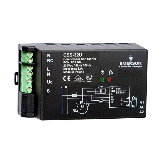
General information and technical data:
Compressor Soft Starters of the CSS-Series are used to limit
1-phase compressors. For additional start torque a built
switched in parallel to the run rapacitor. After start it is switched off.
voltage is continuously monitored. In case of undervoltage the
switched off. Restarts are delayed and indicated by a blinking greed LED.
Restarts are delayed and indicated by a blinking greed LED. In case
of alarm a signal is indicated by the red LED. The alarm relay will be activated.
Soft starters are released for use with many compressors. (See list Fig.3)
CSS-32U for compressor motors with nominal current of 32A max.
for compressor motors with nominal current of 32A max.
CSS-25U for compressor motors with nominal current of 25A max
!
Safety instructions:
• Read installation instructions thoroughly. Failure to comply can result in
Read installation instructions thoroughly. Failure to comply can result in
device failure, system damage or personal injury.
• It is intended for use by persons having the appropriate knowledge and
It is intended for use by persons having the appropriate knowledge and
skill.
• Unauthorised opening of the Soft Starter will void warranty.
• Switch off all voltages / currents before connecting wiring
• Comply with local electrical regulations when wiring.
• Do not exceed operating temperature.
• Do not operate system before all cable connections are completed.
Setting:
• No setting required. The Soft Starters automatically limit
based on the connected compressor size. Several consecutive starts are required
to learn and and optimise the start current of the attached comp
to learn and and optimise the start current of the attached compressor.
Mounting – Dimensions See Fig. 2:
• CSS Soft Starters are for mounting in electrical switch board
mounting clip allows convenient DIN rail fixing; for secure mounting on any
other flat surface, it has four drill holes (Ø4.5mm). The mountin
attached to the housing base in two directions, see fig. 5.
attached to the housing base in two directions, see fig. 5. Protect CSS from
direct sun light and water.
Wiring (Fig. 2):
• Perform wiring as printed on the housing. CSS Contacts:
R
Output motor run winding
RC Output run capacitor
L1 230V 50/60Hz power input
• Warning: Use automatic circuit breaker F with characteristic of circuit control
automatic circuit breaker F with characteristic of circuit control
C. Releasing current 25A for CSS-25U, 32A for CSS-32U.
• Warning: Do not use an additional contactor. CSS could be damaged.
• Warning: Do not connect "Crun" capacitor to the "Run" lead of the motor.
Connect it between RC and S terminals as per wiring diagram.
start capacitor "Cstart" is built in the Soft Starter.
• The terminals are for flexible cable cross section 0.2 ... 4
• The screws must be tightened with 0.5... 0.6 Nm.
• The wiring diagram per Fig.1 is an example how safetyfunctions can be wired.
The wiring diagram per Fig.1 is an example how safetyfunctions can be wired.
Crun Run capacitor
F1
Circuit breaker of control circuit
F2
Discharge gas thermostat
F3
High pressure switch
F4
Low pressure switch
LED Indicator Codes
green
red
Alarm Rel.
ON
OFF
ON
blinking OFF
ON
ON
ON
ON
ON
1 x blink
OFF
ON
2 x blink
OFF
ON
3 x blink
OFF
ON
4 x blink
OFF
ON
5 x blink
OFF
OFF
ON
OFF
OFF
OFF
OFF
OFF
OFF
OFF
CSS__65166___R02.docx
Compressor Soft Starter CSS-Series
Compressor S
Series are used to limit the start current of
built-in start capacitor is
. After start it is switched off. Supply
. In case of undervoltage the compressor is
he alarm relay will be activated.
(See list Fig.3).
ominal current of 25A max.
Starter will void warranty.
connecting wiring.
.
nections are completed.
Starters automatically limits the start current
Several consecutive starts are required
in electrical switch boards only. The
for secure mounting on any
The mounting clip can be
Contacts:
S
Output start winding
start winding
ON Start input ("on"
" if connected to 230V)
N
Neutral line
32U.
could be damaged.
the "Run" lead of the motor.
per wiring diagram. An additional
2
4 mm
.
F6
Circuit breaker of motor
Circuit breaker of motor
K1 Contactor
Q1 Main switch
Main switch
R2 Crankcase heater
Crankcase heater
Message
System energized, normal operation
System energized, normal operation
System energized, waiting for delay time elapsed
System energized, waiting for delay time elapsed
Systemtest after power on
after power on
Motor current too low
Motor current too low
System cannot start caused by low voltage condition
System cannot start caused by low voltage condition
Start winding voltage too low after start sequence
ding voltage too low after start sequence
Motor current too high (32 A eff)
Motor current too high (32 A eff)
Start capacitor error (damaged or disconnected)
Start capacitor error (damaged or disconnected)
Internal error
System not energized or internal power supply defect
System not energized or internal power supply defect
Main cicuit breaker blown at power on
Main cicuit breaker blown at power on
at transport can set bistable relays into wrong position. With this mode the relays will be reset to the correct position).
at transport can set bistable relays into wrong position. With this mode the relays will be reset to the correct position).
at transport can set bistable relays into wrong position. With this mode the relays will be reset to the correct position).
replaces / ersetzt R01
replaces / ersetzt
Operating Instructions
Operation
• After all connections are wired, supply voltage can be switched on.
After all connections are wired, supply voltage can be switched on. Green + red
LED will be on for 30 sec after power up, then
the initial delay time of 150 sec. Then green
the initial delay time of 150 sec. Then green LED on will indicate "ready for
start".
• Switch contact "ON" to 230V (for min. 0.5 sec)
start current. The start sequence is monitored
• If the motor does not start, it is switched
Min. A blinking green LED indicates
• The compressor is switched-off, when "ON" is disconnected from 230V. A
restart will be delayed. This is indicated by
restart will be delayed. This is indicated by a blinking green LED. After elapsed
delay time the green LED will stop blinking
the green LED will stop blinking; a restart is possible instantly.
• For other messages see list of LED indicator codes below
Technical Data
Operating voltage
Continuous compressor current, max.
Compressor start current limited to max.
Compressor start current limited to max.
"ON" Signal
Impedance at "ON" input
Alarm relay, AgNi (SPDT)
Resistive (AC1) max.
Operating temperature
Storage temperature
Start capacitor (Cstart)
Cable cross section, rigid (power lines)
Flexible cable cross section (power lines)
Flexible cable cross section (power lines)
Flexible cable cross section (alarm outp.)
Flexible cable cross section (alarm outp.)
Restart delay
Vibration resistance (10 ... 1000 Hz)
Protection acc. IEC 529
Standards
• Low voltage directive
• Contactors and motor-starters - AC semiconductor motor controllers and
starters
• Electromagnetic Compatibility
• ROHS 2002/95/EC
• UL pending
• Marking:
Productinformation per EN 60947
Productinformation per EN 60947-4-2
Manufacturer:
Type codes:
Nom. operating current:
Operating voltage / Frequency: 230V nom /
Operation category:
Device alternative:
Isolation voltage:
Surge voltage:
Protection acc. IEC 529
Pollution degree:
Remarks
Compressor might be ON or OFF
Compressor might be ON or OFF
Blink frequency 0.5 Hz
Duration ~ 30 sec
Check wiring
Blink frequ. 2.5 Hz, 1.5 sec break between blink packages
Blink frequ. 2.5 Hz, 1.5 sec break between blink packages
Check wiring
Overload; locked rotor
Blink frequ. 2.5 Hz, 1.5 sec break between blink packages
Blink frequ. 2.5 Hz, 1.5 sec break between blink packages
Severe problems, device to be replaced
Severe problems, device to be replaced
If energized device to be replaced
If energized device to be replaced
Remove compressor lines R and RC; switch power on for few sec.
Remove compressor lines R and RC; switc
Reconnect compressor and power on again. (Note: Shock and vibrations
Reconnect compressor and power on again.
PCN 865 724
0 sec after power up, then blinking green LED indicates
to 230V (for min. 0.5 sec) starts the motor with limited
monitored.
it is switched-off. A restart will be delayed for 5
the delay.
off, when "ON" is disconnected from 230V. A
ee list of LED indicator codes below
230 V AC +10% / -15% / 50/60 Hz
CSS-25U: 25 A
CSS-32U: 32 A
45 A
230 V AC +10% / -15% / 50/60 Hz
>440 kOhm
250V~ / 3A
30V= / 3A
-20 ... +55°C
-20 ... +65°C
200 ... 240 uF
0.2 ... 6 mm
0.25 ... 4 mm
0.25 ... 2.5 mm
0,5 ... 5 Min.
4 g
IP 20
LVD 2006/95/EC
AC semiconductor motor controllers and
EN60947-4-2 pending
EMC 2004/108/EC
Ho335-40-2
Emerson Electric GmbH & Co. OHG
Emerson Electric GmbH & Co. OHG
CSS-25
25U CSS-32U
25A
32A max. / AC-53a; AC-58a
230V nom / 50/60Hz
32A, Class 12, 60%
A, Class 12, 60%
Hybrid motor star
Hybrid motor starter with bypassed
semiconductor
semiconductor
2.5 kV
2.5 kV
1.5 kV
1.5 kV
IP-20
2
1 / 8
GB
2
2
2
09.11.2010

Verwandte Anleitungen für Emerson Compressor Soft Starter CSS-Serie


Inhaltszusammenfassung für Emerson Compressor Soft Starter CSS-Serie
-
Seite 2: Betrieb
Verdichters verbunden werden. Er ist zwischen RC und S zu schalten (siehe Produktinformation gemäß EN 60947-4-2: Fig.1). Im Soft Starter befindet sich zusätzlich der Start-Kondensator Cstart. Hersteller: Emerson Electric GmbH & Co. OHG • Die Anschlüsse sind für Kabelquerschnitt 0,2 ... 4mm vorgesehen Typenbezeichungen:... - Seite 8 ZB19KCE-PFJ ZB21KCE-PFJ ZB42KCE-PFJ ZB26KCE-PFJ ZF13KVE-PFJ ZF18KVE-PFJ Fig. 5 Fig. 4 Emerson Electric GmbH & Co OHG - Postfach 1251 - Heerstraße Heerstraße 111 - D-71332 Waiblingen - Germany - Phone .49-(0)7151 (0)7151-509-0 - Fax .49-(0)7151-509-200 www.emersonclimate.eu CSS__65166___R02.docx replaces / ersetzt...