Herunterladen Inhalt Inhalt Diese Seite drucken
autosen AL006 Bedienungsanleitung

autosen AL006 Bedienungsanleitung

Reflexlichtschranke
Inhaltsverzeichnis

Werbung

Verfügbare Sprachen

Verfügbare Sprachen

Bedienungsanleitung
Reflexlichtschranke
Operating instructions
Retro-reflective sensor
Notice d'utilisation
Détecteur reflex
Istruzioni per l'uso
fotocellula reflex
AL006
autosen
DE DE
DE
UK
FR
IT

Werbung

Inhaltsverzeichnis
loading

Inhaltszusammenfassung für autosen AL006

  • Seite 1 Bedienungsanleitung DE DE Reflexlichtschranke Operating instructions Retro-reflective sensor Notice d'utilisation Détecteur reflex Istruzioni per l'uso fotocellula reflex AL006 autosen...
  • Seite 2: Inhaltsverzeichnis

    7�2�2 Empfindlichkeit mit Tripelspiegel / Reflexfolie und Objekt einstellen ��10 7�2�3 Maximale Empfindlichkeit einstellen ���������������������������������������������������10 8 Betrieb ��������������������������������������������������������������������������������������������������������������� 11 9 Wartung, Instandsetzung, Entsorgung �������������������������������������������������������������� 11 1 Vorbemerkung Technische Daten, Zulassungen, Zubehör und weitere Informationen unter www�autosen�com� 1.1 Verwendete Symbole ► Handlungsanweisung > Reaktion, Ergebnis...
  • Seite 3: Sicherheitshinweise

    […] Bezeichnung von Tasten, Schaltflächen oder Anzeigen → Querverweis Information Ergänzender Hinweis� Wichtiger Hinweis Fehlfunktionen oder Störungen sind bei Nichtbeachtung möglich� 2 Sicherheitshinweise • Dieses Dokument vor Inbetriebnahme des Produktes lesen und während der Einsatzdauer aufbewahren� • Das Produkt muss sich uneingeschränkt für die betreffenden Applikationen und Umgebungsbedingungen eignen�...
  • Seite 4: Bestimmungsgemäße Verwendung

    Position des Produktlabels Hinweisschild 3 Bestimmungsgemäße Verwendung In Verbindung mit einem Tripelspiegel oder einer Reflexfolie erfasst die Reflexlichtschranke berührungslos Gegenstände und Materialien und meldet sie durch ein Schaltsignal� 4 Montage ► Den Tripelspiegel oder die Reflexfolie hinter dem zu erfassenden Objekt anbringen�...
  • Seite 5: Bedien- Und Anzeigeelemente

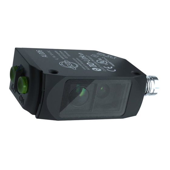
    5 Bedien- und Anzeigeelemente 1: LED grün - Betrieb, Stabilitätsanzeige 2: Taste OUT OFF 3: LED gelb - Schaltausgang aktiv 4: Taste OUT ON 5.1 Stabilitätsanzeige Die grüne LED leuchtet bei anliegender Versorgungsspannung und stabilem Sensorsignal� stabiles Signal Schaltpunkt stabiles Signal Hellschaltung LED grün LED gelb...
  • Seite 6: Elektrischer Anschluss

    6 Elektrischer Anschluss Das Gerät darf nur von einer Elektrofachkraft installiert werden� ► Befolgen Sie die nationalen und internationalen Vorschriften zur Errich- tung elektrotechnischer Anlagen� ► Spannungsversorgung nach EN 50178 sicherstellen� 4 OUT / IO-Link ► Anlage spannungsfrei schalten� ► Gerät folgendermaßen anschließen: 6.1 PNP 4 OUT / IO-Link 7 Einstellungen...
  • Seite 7: 7�1�1 Gerät Soll Schalten, Wenn Das Objekt Erkannt Wird

    7.1.2 Gerät soll nicht schalten, wenn das Objekt erkannt wird ► Das Objekt (wie Abb� 1) platzieren und [OUT OFF] > 2 s drücken� ► Das Objekt (wie Abb� 2) entfernen und [OUT ON] drücken� Die Einstellungen können auch zuerst ohne Objekt und dann mit Objekt durchge- führt werden�...
  • Seite 8: 7�1�4 Programmierung Fehlgeschlagen

    Die zur Konfiguration des Gerätes notwendigen IODDs, detaillierte Informationen über Prozessdatenaufbau, Diagnoseinformationen und Parameteradressen sowie alle notwendigen Informationen zur benötigten IO-Link-Hardware und Software finden Sie unter www�autosen�com� 7.2.1 Einstellbare Parameter Über IO-Link können u�a� die folgenden Parameter eingestellt werden� Eine Tabelle mit allen einstellbaren Parametern finden Sie unter www�autosen�com...
  • Seite 9 Parameter- Werte Beschreibung Standardein- name stellung Teach SP1 TP2 2� Teil der Teachsequenz zur Einstellung N� A� des Schaltpunktes SP1 durch den Teach ohne Objekt� Der 2� Teil der Teachsequenz muss nach der Durchführung des 1� Teils erfolgen� TI Result�State - Idle Teach-In Status, nach einem erfolgreichen N�...
  • Seite 10: 7�2�2 Empfindlichkeit Mit Tripelspiegel / Reflexfolie Und Objekt Einstellen

    7.2.2 Empfindlichkeit mit Tripelspiegel / Reflexfolie und Objekt einstellen ► Software LR DEVICE starten� ► Reflexlichtschranke auf Objekt richten (Abb� 1)� ► [Teach SP1 TP1] in Software LR DEVICE wählen� ► Reflexlichtschranke auf Tripelspiegel oder Reflexfolie richten (Abb� 2)� ► [Teach SP1 TP2] in Software LR DEVICE wählen Es kann zuerst das Objekt und anschließend Tripelspiegel / Reflexfolie oder umgekehrt eingestellt werden�...
  • Seite 11: Betrieb

    8 Betrieb ► Prüfen, ob das Gerät sicher funktioniert� > Die grüne LED leuchtet bei Betriebsbereitschaft� > Einstellung Dunkelschaltung: Der Ausgang ist durchgeschaltet / die gelbe LED leuchtet, wenn ein Objekt erkannt wird� > Einstellung Hellschaltung: Der Ausgang ist durchgeschaltet / die gelbe LED leuchtet, wenn kein Objekt erkannt wird�...
  • Seite 12: Preliminary Note

    7�2�2 Set sensitivity with prismatic reflector / reflective tape and object ������19 7�2�3 Setting the maximum sensitivity ���������������������������������������������������������19 8 Operation �����������������������������������������������������������������������������������������������������������21 9 Maintenance, repair, disposal ����������������������������������������������������������������������������21 1 Preliminary note Technical data, approvals, accessories and further information at www�autosen�com� 1.1 Symbols used ► Instructions > Reaction, result...
  • Seite 13: Safety Instructions

    […] Designation of keys, buttons or indications → Cross-reference Information Supplementary note� Important note Non-compliance may result in malfunction or interference� 2 Safety instructions • Read this document before setting up the product and keep it during the entire service life� •...
  • Seite 14: Functions And Features

    Position of the product label Explanatory label 3 Functions and features In conjunction with a prismatic reflector or reflective tape the retro-reflective sensor detects objects and materials without contact and indicates their presence by a switching signal� 4 Installation ► Fit the prismatic reflector or the reflective tape behind the object to be detected� ►...
  • Seite 15: Operating And Display Elements

    5 Operating and display elements 1: LED green - operation, stability indication 2: OUT OFF button 3: LED yellow - switching output active 4: OUT ON button 5.1 Stability indication The green LED is on when the supply voltage is applied and the sensor signal is stable�...
  • Seite 16: Electrical Connection

    6 Electrical connection The unit must be connected by a qualified electrician� ► The national and international regulations for the installation of electri- cal equipment must be adhered to� ► Ensure voltage supply to EN 50178� ► Disconnect power� 4 OUT / IO-Link ►...
  • Seite 17: Settings

    7 Settings 7.1 Settings on the sensor 7.1.1 The sensor is to switch when the object is detected ► Position the object� Fig� 1 ► Press [OUT ON] for > 2 s� > The yellow LED flashes� > The setting of the sensitivity with object is made by releasing [OUT ON]�...
  • Seite 18: 7�1�4 Programming Unsuccessful

    IO-Link hardware and software can be found at www�autosen�com� 7.2.1 Adjustable parameters Among others, the following parameters can be set via IO-Link� A table of all adjustable parameters can be found at www�autosen�com Parameter Values Description...
  • Seite 19 Parameter Values Description Default name Teach SP1 TP2 2� Part of the teach sequence to set switch N� A� point SP1 by teach without object� The second part of the teach sequence has to be carried out after the first part� TI Result�State - Idle Teach-in status;...
  • Seite 20: 7�2�2 Set Sensitivity With Prismatic Reflector / Reflective Tape And Object

    7.2.2 Set sensitivity with prismatic reflector / reflective tape and object ► Start the LR DEVICE software� ► Align the retro-reflective sensor to the object (Fig� 1)� ► Press [Teach SP1 TP1] in the LR DEVICE software� ► Align the retro-reflective sensor to the prismatic reflector or reflective tape (Fig�...
  • Seite 21: Operation

    8 Operation ► Check whether the unit operates correctly� > The green LED is on when the unit is ready for operation� > Setting the dark-on mode: the output is switched / the yellow LED is lit when an object is detected� >...
  • Seite 22: Remarque Préliminaire

    �������������������������������������������������������������������������������������������������30 7�2�3 Réglage de la sensibilité maximale ����������������������������������������������������30 8 Fonctionnement �������������������������������������������������������������������������������������������������30 9 Entretien, réparation et élimination ��������������������������������������������������������������������31 1 Remarque préliminaire Données techniques, homologations, accessoires et informations supplémentaires sur www�autosen�com� 1.1 Symboles utilisés ► Action à faire > Retour d'information, résultat...
  • Seite 23: Consignes De Sécurité

    […] Désignation d'une touche, d'un bouton ou d'un affichage → Référence croisée Information Remarque supplémentaire� Remarque importante Le non-respect peut aboutir à des dysfonctionnements ou perturbations� 2 Consignes de sécurité • Lire ce document avant la mise en service du produit et le garder pendant le temps d'utilisation du produit�...
  • Seite 24: Fonctionnement Et Caractéristiques

    Position de l'étiquette du produit Panneau indicateur 3 Fonctionnement et caractéristiques En combinaison avec un réflecteur "nid d'abeille" ou une bande adhésive, le dé- tecteur reflex détecte des objets et matières sans contact et indique leur présence par un signal de commutation� 4 Montage ►...
  • Seite 25: Eléments De Service Et D'indication

    5 Eléments de service et d'indication 1: LED verte - fonctionnement, affichage de stabilité 2: Bouton-poussoir OUT OFF 3: LED jaune - sortie de commutation active 4: Bouton-poussoir OUT ON 5.1 Affichage de stabilité La LED verte s'allume en cas de tension d'alimentation fournie et signal stable du détecteur�...
  • Seite 26: Raccordement Électrique

    6 Raccordement électrique L'appareil doit être raccordé par un électricien qualifié� ► Les règlements nationaux et internationaux relatifs à l'installation de matériel électrique doivent être respectés� ► Assurer une alimentation en tension selon EN 50178� ► Mettre l'installation hors tension� ►...
  • Seite 27: Réglages

    7 Réglages 7.1 Réglage sur l'appareil 7.1.1 L'appareil doit commuter lorsque l'objet est détecté ► Positionner l'objet� Fig� 1 ► Appuyer sur [OUT ON] pendant > 2 s� > La LED jaune clignote� > Le réglage de la sensibilité avec objet s'effectue en relâchant [OUT ON]�...
  • Seite 28: 7�1�4 Programmation Non Réussie

    IO-Link sont disponibles sur www�autosen�com� 7.2.1 Paramètres réglables Entre autres, les paramètres suivants peuvent être réglés via IO-Link�...
  • Seite 29 Nom de pa- Valeurs Description Réglage par ramètre défaut Teach SP1 TP1 Première partie de la séquence n�a� d'apprentissage pour le réglage du seuil de commutation SP1 par apprentissage sur l'objet� Les deux parties de la séquence d'apprentissage pour TP1 et TP2 (TP = point d'apprentissage) doivent être effec- tuées�...
  • Seite 30: 7�2�2 Régler La Sensibilité Avec Le Réflecteur "Nid D'abeille" / La Bande Adhé

    Nom de pa- Valeurs Description Réglage par ramètre défaut Number of 0 ��� Nombre d'opérations de démarrage n�a� power cycles 65535 (power-up) du détecteur Operating hours 0 ��� Heures de fonctionnement n�a� 65535 7.2.2 Régler la sensibilité avec le réflecteur "nid d'abeille" / la bande adhé- sive et l'objet ►...
  • Seite 31: Fonctionnement

    8 Fonctionnement ► Vérifier le bon fonctionnement de l'appareil� > La LED verte est allumée si l'appareil est opérationnel� > Réglage obscurcissement : la sortie est commutée / la LED jaune est allumée lorsqu'un objet est détecté� > Réglage éclairement : la sortie est commutée / la LED jaune est allumée lorsque aucun objet n'est détecté�...
  • Seite 32 Inhalt Premessa ���������������������������������������������������������������������������������������������������33 1�1 Simboli utilizzati ���������������������������������������������������������������������������������������33 Indicazioni di sicurezza �����������������������������������������������������������������������������������33 Uso conforme �������������������������������������������������������������������������������������������������34 Montagio ���������������������������������������������������������������������������������������������������34 Elementi di comando e di indicazione ������������������������������������������������������������35 5�1 Indicazione di stabilità������������������������������������������������������������������������������35 Collegamento elettrico ������������������������������������������������������������������������������������36 7 7 Impostazioni ���������������������������������������������������������������������������������������������������36 7�1 Impostazione sul dispositivo ��������������������������������������������������������������������36 7�1�1 Il dispositivo deve commutare quando viene rilevato l'oggetto ���������36 7�1�2 Il dispositivo non deve commutare quando viene rilevato l'oggetto ��37 7�1�3 Impostazione della portata massima ������������������������������������������������37 7�1�4 Programmazione non riuscita �����������������������������������������������������������38...
  • Seite 33: Premessa

    1 Premessa 1.1 Simboli utilizzati ► Istruzioni operative > Reazione, risultato […] Denominazione di tasti, pulsanti o indicazioni → Riferimento incrociato Informazioni Nota aggiuntiva� Avviso importante Rischio di malfunzionamenti o anomalie in caso di mancata osservanza� 2 Indicazioni di sicurezza •...
  • Seite 34: Uso Conforme

    Etiquette supplémentaire 3 Uso conforme In abbinamento a un catarifrangente o a una pellicola riflettente, la fotocellula reflex rileva senza contatto oggetti e materiali, segnalandoli attraverso un segnale di commutazione� 4 Montaggio ► Applicare il catarifrangente o la pellicola riflettente dietro l'oggetto da rilevare� ►...
  • Seite 35: Elementi Di Comando E Di Indicazione

    5 Elementi di comando e di indicazione 1: LED verde - funzionamento, indicazione di stabilità 2: Tasto OUT OFF 3: LED giallo - uscita di commutazione attiva 4: Tasto OUT ON 5.1 Indicazione di stabilità Il LED verde si accende quando è presente la tensione d'alimentazione e il segnale del sensore è...
  • Seite 36: Collegamento Elettrico

    6 Collegamento elettrico Il dispositivo può essere installato esclusivamente da personale elettrotecnico specializzato� ► Attenersi alle norme nazionali e internazionali per l'installazione di attrezzature elettrotecniche� ► Assicurare l'alimentazione di tensione come da norma EN 50178 4 OUT / IO-Link ► Togliere tensione all'impianto� ►...
  • Seite 37: 7�1�2 Il Dispositivo Non Deve Commutare Quando Viene Rilevato L'oggetto

    7.1.2 Il dispositivo non deve commutare quando viene rilevato l'ogge ► Posizionare l'oggetto (come nella fig� 1) e premere [OUT OFF] > 2 s ► Rimuovere l'oggetto (come nella fig� 2) e premere [OUT ON]� Le impostazioni possono essere effettuate inizialmente senza oggetto e poi con l'oggetto�...
  • Seite 38: 7�1�4 Programmazione Non Riuscita

    IO-Link richiesti sono disponibili sul sito www�autosen�com� 7.2.1 Parametri impostabili Tramite IO-Link è possibile tra le altre cose impostare i seguenti parametri�...
  • Seite 39 Nome para- Valori Descrizione Impo- metro stazione standard Teach SP1 TP1 1� parte della sequenza teach per impostare N� A� il punto di commutazione SP1 attraverso il teach sull'oggetto� Devono essere eseguite entrambe le parti della sequenza teach per TP1 e TP2 (TP = punto Teach)� Teach SP1 TP2 2�...
  • Seite 40: 7�2�2 Impostazione Della Portata Con Sfondo E Oggetto

    7.2.2 Impostazione della sensibilità con catarifrangente / pellicolariflettente e oggetto ► Avviare il software� ► Allineare la fotocellula reflex rispetto all'oggetto (fig� 1)� ► Selezionare [Teach SP1 TP1] nel software� ► Allineare la fotocellula reflex rispetto al catarifrangente o alla pellicola riflettente (fig�...
  • Seite 41: Funzionamento

    8 Funzionamento ► Controllare che il dispositivo funzioni correttamente e in modo sicuro� > Lo stato di operatività è indicato dall'accensione del LED verde� > Impostazione commutazione impulso buio: l'uscita è collegata / il LED giallo si accende quando non risulta rilevato nessun oggetto� >...
  • Seite 44 Technische Daten und weitere Informationen unter: Données techniques et informations supplémentaires sur notre site web à: Technical data and further information at: Dati tecnici e altre informazioni si trovano su : www.autosen.com...

Inhaltsverzeichnis