Werbung
Verfügbare Sprachen
Verfügbare Sprachen
Quicklinks
102 mm
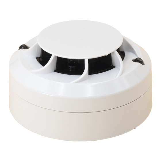
B501AP
INSTALLATION AND MAINTENANCE
INSTRUCTIONS FOR MODEL 22051E(I) PHOTO
ENGLISH
ELECTRONIC SMOKE SENSOR
GENERAL DESCRIPTION
Models 22051E and 22051EI are intelligent plug-in type smoke sensors that combine
a photoelectronic sensing chamber with addressable communications. These sensors
are designed for open area protection and must only be connected to control panels
that use a compatible proprietary communication protocol for monitoring and control.
The 22051EI sensor contains an isolator, if installing this version check the panel
documentation for details of how many isolators can be used on a loop.
Two LEDs on each sensor light to provide a local 360
of LEDs are dependent on panel). Remote LED indicator capability is available as an
optional accessory wired to the standard base terminals (again dependent on panel).
SPECIFICATIONS
Operating Voltage Range:
Max. Standby Current (no comm.): 200 µA @24 V and 25
(comm. LED blink enabled - 5 sec) 300 µA @24 V and 25
(Read 16 sec. LED blink 8 sec)
Max. Alarm Current (LED on):
Operating Humidity Range:
Isolator Characteristics (22051EI Only)
Maximum rated continuous current with the isolator closed (Ic max): 1A
Maximum rated isolator current (under short circuit) (Is max): 1A
Max. leakage current (IL max) with the isolator open (isolated state): 15mA
Max. series impedance with the isolator closed (Zc max): 170 m ohm at 15Vdc
Independently tested and certified to: EN54-7: 2000 (and EN54-17: 2005 for EI)
WIRING GUIDE
Refer to the installation instructions supplied with the plug-in sensor bases for wiring
details. All bases are provided with terminals for power and an optional Remote Indicator.
Note 1: All wiring must conform to applicable local and national codes and regulations.
Note 2: Verify that all sensor bases are installed and that polarity of the wiring is correct
at each base.
Disconnect loop power before installing sensors. Notify proper authorities.
SENSOR INSTALLATION
1. Set the sensor address (see figure 1) by turning the two rotary switches on the
underside of the sensor, selecting a number between 01 and 159. (Note: The
number of addresses available will be dependent on panel capability, check the panel
documentation for information on this). Record the address on the label attached
to the base.
Figure 1: Rotary Address Switches
X 10
2. Insert the sensor into the base and rotate it clockwise until it locks into place.
3. After all the sensors have been installed, apply power to the system.
4. Test the sensor as described under TESTING.
5. Reset the sensor by communication command from the panel.
Tamper-Resistance.
These sensors includes a feature that, when activated, prevents removal of the sensor
from the base without the use of a tool. Refer to the installation instructions for the
sensor base for details of how to use this feature.
Dust covers help to protect units during shipping and when first installed.
They are not intended to provide complete protection against contamination
therefore sensors should be removed before construction, major re-decoration
or other dust producing work is started. Dust covers must be removed before
system can be made operational.
D200-200-00
22051E(I)
ND22051E(I)
70°C
97 g
-30°C
o
visible sensor indication (operation
15 to 32 VDC (15 to 28 for 22051EI isolated)
C
o
C
o
220 µA @24 V and 25
C
o
add 50 µA for 22051EI Isolated
add 3.5 mA @ 24 V and 25
C
o
10% to 93% Relative Humidity, Non-Condensing
WARNING
X 1
CAUTION
DOP-IFD128: 22051E, ND22051E
0786
DOP-IFD129: 22051EI, ND22051EI
09
EN54-7: 2000, EN54-17: 2005 (EI only)
Figure 2: Cleaning the Sensor
Cover Removal Tabs
Sensing Chamber Cover
Sensing Chamber
MAINTENANCE
Before cleaning, disable the system to prevent unwanted alarms:
1. Remove the sensor to be cleaned from the system.
2. Gently release each of the four cover removal tabs that hold the cover in place (see
figure 2) and remove the sensor cover.
3. Vacuum the outside of the screen/chamber cover carefully without removing it.
4. Remove the screen/chamber cover assembly by pulling it straight out.
5. Use a vacuum cleaner and/or clean, compressed air to remove dust and debris from
the sensing chamber and sensing chamber cover.
6. Re-install the sensing chamber cover by aligning the square and round holes on the
cover with the square and round pins around the sensing chamber, gently pressing
it home until it slips into place (Note: Arrows on the plastic indicate the positioning
when replacing the chamber cover and air guide.
7. Re-install the sensor cover. Use the cover removal tabs and LEDs to align the cover
with the sensor. Snap the cover into place.
8. When all sensors have been cleaned, restore power to the loop and test the sensor(s)
as described under TESTING.
TESTING
Sensors must be tested after installation and following periodic maintenance. Disable
the zone or system undergoing maintenance to prevent unwanted alarms.
Test the sensors as follows:
Magnet Method
1. Test the sensor by positioning the test magnet (model M02-04-00 optional) against
the sensor body approximately 2cm from LED 1, indicated by a mark on the sensor
cover as shown in figure 3.
2. Both LED's on the sensor should latch into alarm within 30 seconds, activating the
control panel.
Figure 3: Test Magnet Position
Smoke Method
1. Using generated smoke, or synthetic smoke aerosol from an approved manufacturer
such as No Climb Products Ltd, subject the sensor to controlled amounts of smoke
in accordance with local codes of practice and manufacturer recommendations.
2. Both LED's on the sensor should latch into alarm within 30 seconds, activating the
control panel.
After completion of the test notify the proper authorities that the system is operational.
LIMITATIONS OF SMOKE SENSORS
Smoke sensors must be used in conjunction with compatible equipment.
Smoke sensors will not sense fires which start where smoke does not reach the sensors.
A sensor may not detect a fire developing on another level of a building.
Smoke sensors also have sensing limitations. Consideration must be made of the
environment when selecting fire sensors.
Smoke sensors cannot last forever. Smoke sensors contain electronic parts. Even
though sensors are made to last over 10 years, any of these parts could fail at any
time. Therefore, test your smoke detection system at least semi-annually. Clean and
take care of your smoke sensors regularly. Taking care of the fire detection system you
have installed will significantly reduce your product liability risks.
Pittway Tecnologica S.r.l, Via Caboto 19/3, 34147 Trieste, Italy
Honeywell Products and Solutions Sàrl
(Trading as System Sensor Europe)
Zone d'activités La Pièce 16
CH-1180 ROLLE, Switzerland
Sensor Cover
and Screen
LED 2
Mark on Cover
Test Magnet
LED 1
WARNING
I56-3399-005
Werbung

Verwandte Anleitungen für System Sensor 22051E

Inhaltszusammenfassung für System Sensor 22051E
- Seite 1 ELECTRONIC SMOKE SENSOR GENERAL DESCRIPTION Models 22051E and 22051EI are intelligent plug-in type smoke sensors that combine a photoelectronic sensing chamber with addressable communications. These sensors are designed for open area protection and must only be connected to control panels MAINTENANCE that use a compatible proprietary communication protocol for monitoring and control.
- Seite 2 Camera di rilevazione DESCRIZIONE GENERALE I sensori fotoelettronici intelligenti 22051E e 22051EI sono sensori di fumo a innesto che combinano una camera di rilevazione fotoelettronica con comunicazioni indirizzabili. Questi sensori sono stati progettati per garantire la protezione di aree aperte e devono pertanto essere collegati esclusivamente a pannelli di controllo che per il monitoraggio e il controllo utilizzano un protocollo di comunicazione compatibile di proprietà.
- Seite 3 Cámara de detección DESCRIPCIÓN GENERAL Los sensores ópticos analógicos 22051E y 22051EI combinan una cámara de detección con comunicaciones direccionables. Estos sensores se han diseñado para proporcionar protección en zonas diáfanas y solo deben conectarse a centrales con protocolo de comunicaciones compatible para realizar la supervisión.
- Seite 4 MODELL 22051E(I) OPTISCHER RAUCHMELDER Messkammer ALLGMEIN Die Modelle 22051E und 22051EI sind intelligente, optische Rauchmelder die eine optische Messkammer mit einer adressierbaren Kommunikation verbinden. Diese Melder sind für Normalbereiche (ohne EX-Schutz) vorgesehen und dürfen nur an Brandmelderzentralen angeschlossen werden, welche ein kompatibles Kommunikationsprotokoll verwenden.