Flomec TM Serie Handbuch
Electronic water meters
Inhaltsverzeichnis
Verfügbare Sprachen
Verfügbare Sprachen
Quicklinks
SAVE THESE INSTRUCTIONS
TM Series Electronic Water Meters
User Manual
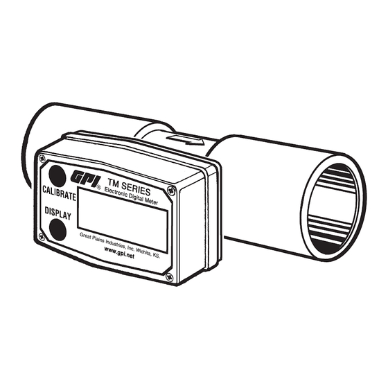
TM Meter with Computer Display
TABLE OF CONTENTS
English ...........................................................1
Español ..........................................................8
Deutsch .......................................................15
Italiano .........................................................22
Français .......................................................29
E N G L I S H
IMPORTANT NOTICE
Use TM Series meters with water and other
chemicals compatible with wetted compo-
nents. Do not use to meter fuel or incompatible
chemicals. TM Series meters are available with
either a computer for local electronic display, or
a conditioned signal output module to provide a
digital signal to customer interfacing equipment.
TM Series meters with computer display mea-
sure in gallons or litres. Refer to the Calibration
Section for details.
03/17
TM Digital Pulse Meter
These meters are not legal for trade applications.
TM Series meters are very sensitive to electric
noise if operated within 1 to 2 inches of some
electric motors or other sources of electronic
noise.
INSTALLATION
Connections
Install your meter in-line either horizontally or
vertically or at the end of the hose adjacent to
the nozzle. Installation to metal connections is
not recommended. Install as follows:
1. Plan to install turbine with a minimum straight
pipe length as follows:
• Upstream from the turbine, allow a mini-
mum straight pipe length of 10 times the
internal diameter of the turbine.
• Downstream from the turbine, allow a
minimum straight pipe length of 5 times
the internal diameter of the turbine.
2. For Spigot (Pipe) End use only primer and
solvents approved for PVC gluing.
For NPT and BSP Fittings wrap all connec-
tions with 3 to 4 wraps of thread tape (optional
to use pipe thread sealant). Make sure the
tape does not intrude into the flow path.
920786-02 Rev. C
Inhaltsverzeichnis

Inhaltszusammenfassung für Flomec TM Serie
-
Seite 15: Deutsch
D E U T S C H PRECAUCIÓN No devolver el metro sin la autoridad específica del departamento de servicios WICHTIGE HINWEISS al cliente de GPI. Debido a las regulaciones terminantes gubernamentales GPI no Die TM Series Meßinstrumente mit Wasser und aceptará... -
Seite 16: Konditioniertes Signal Ausgeben Baugruppenverdrahtung
Sicherstellen, dass das Klebeband nicht den VORSICHT Durchflussweg stört. Montage in der Nähe starker elektromag- 3. Das Messgerät mit dem Pfeil in Richtung netischer Felder oder starker Stromfelder der Flüssigkeitsströmung befestigen. wird nicht empfohlen und kann zu falschen Messwerten führen. 4. -
Seite 17: Betrieb
10 Fuß (3 m) Kabel wird mit dem Modul versehen. Taste für 3 Sekunden wieder auf die Batch-Total Das Kabel zur gewünschten Länge trimmen oder auf Null. das Kabel wie benötigt verlängern. Wenn die Flüssigkeit fließt durch das Messgerät, ein kleiner Propeller-Symbol markiert ist. MeßinstrumentGenauigkeit Hinweis: Summierung zählt Einheiten insgesamt, Überprüfen... -
Seite 18: Kalibrierung
Wechseln zwischen verschiedenen Einheiten Einstellungen sind in jedem Computer während werden nicht beschädigt die Total-Inhalten. der Herstellung programmiert, unter Verwend- Zum Beispiel, im GL-Modus, den Computer ung von Wasser bei 70° C (21° C). Messwerte mit summiert 10,00 Gallone, wenn der Benutzer Hilfe der Factory Calibration (FAC) ist möglich- schaltet in den LT, erscheint auf dem Anzeige erweise nicht in einigen Situationen richtig, zum... -
Seite 19: Wartung
festgestellt. Dieser K-Faktor kann für Kalibrier- oder entfernt worden sind. Die Fabrik- und ung “des einzelnen Punktes” verwendet werden Nacheichung bleibt erhalten. und wird eine annehmbare Genauigkeit liefern. Wenn die Anzeige schwächer wird, leer oder Jedoch können die Messwerte möglicherweise nicht genau sein, wenn Sie diese Kalibrierung WARNUNG Methode in einigen Situationen verwenden. -
Seite 20: Spezifikationen
daß der positive Pfosten in der richtigen Maßeinheit der Maßnahme: Gallone Position ist. FlußStrecke: ½ Zoll 1 - 10 GPM 4. Wenn die Batterien ausgetauscht sind,zeigt ¾ Zoll 2 - 20 GPM die Frontplatte “POWER ON”. Die Anzeige 1 Zoll 5 - 50 GPM überprüfen, um normale Funktionen sicher- 1 ½... - Seite 21 Lesens (Genauig-keit kann mit verbessert 125508-04 1 /2 Zoll, NPT, PVC, Turbineein- heitsinstallationssatz werden auffangen Kalibrierung) 125510-03 ¾ Zoll, Turbineeinheits- Betriebstemperatur: 0° zu +60° C installationssatz (Flüssigkeit nicht innerhalf des Meßinstru- 125510-04 ¾ Zoll, NPT, PVC, Turbineein- ments einfrieren lassen.) heitsinstallationssatz 125512-03 1 Zoll, Turbineeinheits-...