VIDEOLARM FDW75C2N Bedienungsanleitung
www.videolarm.com
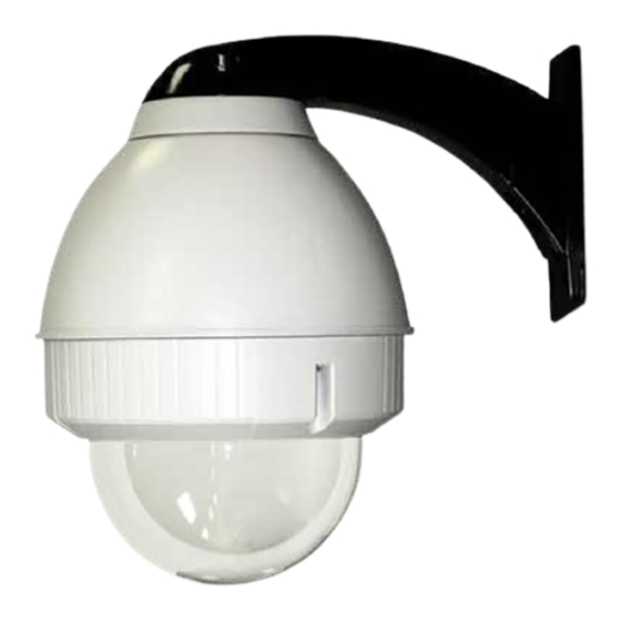
F D W 7 5
Fusion Dome (Outdoor Wall Mount with Housing)
Installation and Operation Instructions for the following models:
FDW75C2N
IP Network Ready 7" Outdoor dome hsg w/wall mount, clear dome, w/24Vac input, heater/
blower, fan an IP Network PTZ camera, 120 to 24Vac transformer.
FDP75C2N
IP Network Ready 7" Outdoor dome hsg w/pendant mount, clear dome, w/24Vac input, heater/
blower, fan an IP Network PTZ camera,120 to 24Vac transformer.
IFDW75CN
IP Network Ready 7" Indoor dome hsg w/wall mount, clear dome, w/24Vac input, heater/
blower, fan an IP Network PTZ camera, 120 to 24Vac transformer.
IFDP75CN
IP Network Ready 7" Indoor dome hsg w/pendant mount, clear dome, w/24Vac input, heater/
blower, fan an IP Network PTZ camera,120 to 24Vac transformer.
FDW75C2NE
IP Network Ready 7" Outdoor dome hsg w/wall mount, clear dome, w/24Vac input, heater/
blower, fan an IP Network PTZ camera. (European Model)
FDP75C2NE
IP Network Ready 7" Outdoor dome hsg w/pendant mount, clear dome, w/24Vac input, heater/
blower, fan an IP Network PTZ camera. (European Model)
FDW75C2N/AC
IP Network Ready 7" Outdoor dome hsg w/wall mount, clear acrylic dome, w/24Vac input, heater/
blower, fan an IP Network PTZ camera, 120 to 24Vac transformer.
FDP75C2N/AC
IP Network Ready 7" Outdoor dome hsg w/pendant mount, clear dome, w/24Vac input, heater/
blower, fan an IP Network PTZ camera,120 to 24Vac transformer.
B e fo r e a t t e m p t i n g t o c o n n e c t o r o p e r a t e t h i s p r o d u c t ,
p l e a s e r e a d t h e s e i n s t r u c t i o n s c o m p l e t e l y.
81-IN5358R1
Inhaltsverzeichnis

Inhaltszusammenfassung für VIDEOLARM FDW75C2N
- Seite 1 F D W 7 5 Fusion Dome (Outdoor Wall Mount with Housing) Installation and Operation Instructions for the following models: FDW75C2N IP Network Ready 7” Outdoor dome hsg w/wall mount, clear dome, w/24Vac input, heater/ blower, fan an IP Network PTZ camera, 120 to 24Vac transformer. FDP75C2N IP Network Ready 7” Outdoor dome hsg w/pendant mount, clear dome, w/24Vac input, heater/ blower, fan an IP Network PTZ camera,120 to 24Vac transformer.
- Seite 2 IMPORTANT SAFEGUARDS SAFETY PRECAUTIONS IMPORTANT SAFEGUARDS SAFETY PRECAUTIONS Read these instructions. 1 Read Instructions - All the safety and operating Keep these instructions. instructions should be read before the unit is CAUTION CAUTION operated. Heed all warnings RISK OF ELECTRIC SHOCK RISK OF ELECTRIC SHOCK 2 Retain Instructions - The safety and operating DO NOT OPEN...
-
Seite 3: Limited Warranty
1. NOTIFICATION OF CLAIMS: WARRANTY SERVICE: If Purchaser believes that the Product is defective in material or workmanship, then written notice with an explanation of the claim shall be given promptly by Purchaser to Videolarm but all claims for warranty service must be made within the warranty period. -
Seite 4: Electrical Specifications
Electrical Specifications Contents of Box FDW75 Power 24VAC Class 2 Only 24 VAC 26 Watts Accessories: Heater: 25 Watts, Blower: 1 Watt Camera Power: 40 Watts Max Tools Required: .100” Flat Head Screwdriver Phillips Head Screwdriver English 24 VAC 26 vatios Accesorios: Calentador: 25 Vatios, Soplador: 1 vatio Energía De la Cámara fotográfica:... - Seite 5 WALL MOUNTING Securely mount unit to wall or to appropriate If using conduit connect, connect to adapter bracket. incoming conduit fitting. • Monte con seguridad la unidad a la pared o al • Si usa el conducto conecte, conecte con la guar- soporte apropiado del adaptador.
- Seite 6 FOR PENDENT/ WALL MOUNTING Wrap Teflon tape around the pipe threads Securely mount bracket to wall. Pull wiring to ensure a tight seal. through bracket and position grommet as shown. • Con seguridad soporte del montaje a emparedar. Tire del cableado •...
- Seite 7 Loop the lanyard over the set screw to Make the appropriate wiring connections temporarily hold housing. from the dome to the gooseneck. • Coloque el acollador sobre el tornillo de presión para • Haga las conexiones apropiadas del cableado de la bóveda celebrar temporalmente la cubierta.
- Seite 8 RJ45 24VAC POWER Camera Max 40 Watts Camera Orange Heater/Blower Yellow 26 Watts Heater/Blower Green Alarm 1 Blue Alarm 2 Violet Alarm 3 Gray Common White Make the appropriate male and female connections. Indoor model does not include pre-run cables. •...
- Seite 9 Axis 213 (3) #8x3/8” ½" 2539 Mounting Plate Captive Screw 1" 2" Mounting Mounting Hole Hole Install the camera to the mounting plate with (2) #10 screws and lock washers provided. Place (3) #8x3/8” screws on the spacers and align the mounting slots. Slide on plate and camera then secure. •...
- Seite 10 Axis 215 (3) #8x3/8” 1" Captive Screw 1" MOUNTING HOLE MOUNTING HOLE 2" AXIS215-VL3026 Install the camera to the mounting plate with (4) #8 screws and lock washers provided. Place (3) #8x3/8” screws on the spacers and align the mounting slots. Slide on plate and camera then secure. •...
- Seite 11 AXIS 231-232D Axis 231D/232D Mounting Hole Loosen Screw Mounting Mounting Hole Hole Loosen the screw to the right of the tab by Use the (3) keyhole slots indicated above. approximately (5) turns. • Utilice (3) las ranuras del ojo de la cerradura indicadas •...
- Seite 12 Connection Module Screw Power Board Remove the power board located inside the housing. Attach the connection module as shown. This is what the typical path of illumination will look like with the setting at 30 degrees. Attach this assembly to the housing using (1) 6-32x3/8” screw and star washer. •...
- Seite 13 Axis 233D Mounting Hole Power Board Mounting Hole Disconnect the orange, red, and black wires. Remove the Use the holes indicated above to mount power board in the housing by loosening screws on the the camera. terminal block and the (4) machine screws. •...
- Seite 14 Quick Release Plate Additional Spacers Keyhole Slots Camera Bracket Base Bracket Mount the Axis 233D camera bracket and quick release plate using the additional spacers from This is what the typical path of illumination will look like with the setting at 30 degrees. the hardware packet.
- Seite 15 Canon VB-C10R ½" 2539 Mounting Plate Captive Screw 1" 2" Mounting Mounting Hole Hole Mount the camera to the 2539 plate using the provided hardware. Place (3) 8 x 32 x 3/8 Phillips head screws on the top of the spacer as shown above. Slide plate in and secure. Monte la cámara fotográfica a la placa 2539 usando el hardware proporcionado.
- Seite 16 Canon VC-C4R/VC-C50IR (3) 8 x 32 x 3/8 1" 2539 Mounting Plate Mounting Hole Captive Screw 1" 2" Mounting Hole Mount the camera to the 2539 plate using the provided hardware. Place (3) 8 x 32 x 3/8 Phillips head screws on the top of the spacer as shown above. Slide plate in and secure. •...
- Seite 17 Elmo PTC-201 2539 Mounting Plate Mounting Hole Captive Screw ½" 2" Mounting Hole Place the camera onto the quick release bracket using the (4) metric 3M Phillips head screws provided. Place the screws on the spacers. Slide on the plate and camera then secure. •...
- Seite 18 Elmo PTC-401 2539 Mounting Plate Mounting Hole Quick release 1" plate Captive Screw 2" Mounting Hole Attach quick release bracket to mounting plate using (4) #8 screws and star washer. Complete assembly as shown, then secure camera to the quick release plate. •...
- Seite 19 JVC VN-C625U / TK-625U 1" Mounting 2630 Mounting 1" Hole Plate Remove the cover and detach bracket. Attach (4) 1” spacers to the 2630 mounting plate and (4) to the main bracket. Place (3) 8x32x3/8” Phillips screws onto the spacers. Secure plate and camera. •...
- Seite 20 Panasonic BB-HCM381/580/581 & KX-HMC280 ½" 2539 Mounting Plate 1" 2" Mounting Hole Install the camera to the bracket with the 1/4x20” washer and lock washer. Place (3) 8x32x3/8” screws on the spacers. Slide on the camera and plate then secure. •...
- Seite 21 Sony SNCRZ25 Mounting Hole 1" 2539 Mounting Plate Mounting Hole Attach bracket with (1) 1/4x20 bolt, washer and lock washer and (2) 3mm x 8mm Phillip head screws and lockwashers. Place the screws on the spacers. Slide on the plate and camera then secure. •...
- Seite 22 Sony SNCRZ50 Mounting Hole ½" 2" 2539 Mounting Mounting Hole Plate Attach bracket with 3mm x 8mm bolts and lock washers. Place (3) 8x32x3/8”screws on the spacers. Slide on the plate and camera then secure. • Una el soporte con los pernos de 3m m x de 8m m y las arandelas de cerradura. Coloque (3) 8x32x3/8"screws en los espaciadores.
- Seite 23 Before After Align the arrows on the outside of the dome Loop the lanyard around the tab inside the housing. and lock. • Alinee las flechas en el exterior de la bóveda y • Coloque el acollador alrededor de la lengüeta trábese.
-
Seite 24: Replacement Parts List
Replacement Parts List FDW75 1 1 1 Part Number Description RPFD7501 LOWER TRIM RING FD7T TINTED REPLACEMENT CAPSULE FD7C CLEAR REPLACEMENT CAPSULE RPFD703 DOME CLAMPING BRACKET RPFD072 24 VAC HEATER RPFD080 (12 VDC) BLOWER (USED IN 24V HOUSINGS) RPFD060 CAMERA BRACKET RPFD050 (MODEL FD7HB) CONNECTION PCB (24VAC ONLY) RPRH707 (MODEL FD7NHB) -
Seite 25: Product Information
Product Registration/Warranty Thank you for choosing Videolarm. We value your patronage and are solely committed to providing you with only the highest quality products available with unmatched customer service levels that are second-to-none in the security industry. Should a problem arise, rest assure that Videolarm stands behind its products...