Herunterladen Inhalt Inhalt Diese Seite drucken

Werbung

Verfügbare Sprachen
  • DE

Verfügbare Sprachen

  • DEUTSCH, seite 38
Version 1.0
Published February 2017
Copyright©2017 ASRock INC. All rights reserved.
Copyright Notice:
No part of this documentation may be reproduced, transcribed, transmitted, or
translated in any language, in any form or by any means, except duplication of
documentation by the purchaser for backup purpose, without written consent of
ASRock Inc.
Products and corporate names appearing in this documentation may or may not
be registered trademarks or copyrights of their respective companies, and are used
only for identification or explanation and to the owners' benefit, without intent to
infringe.
Disclaimer:
Specifications and information contained in this documentation are furnished for
informational use only and subject to change without notice, and should not be
constructed as a commitment by ASRock. ASRock assumes no responsibility for
any errors or omissions that may appear in this documentation.
With respect to the contents of this documentation, ASRock does not provide
warranty of any kind, either expressed or implied, including but not limited to
the implied warranties or conditions of merchantability or fitness for a particular
purpose.
In no event shall ASRock, its directors, officers, employees, or agents be liable for
any indirect, special, incidental, or consequential damages (including damages for
loss of profits, loss of business, loss of data, interruption of business and the like),
even if ASRock has been advised of the possibility of such damages arising from any
defect or error in the documentation or product.
This device complies with Part 15 of the FCC Rules. Operation is subject to the following
two conditions:
(1) this device may not cause harmful interference, and
(2) this device must accept any interference received, including interference that
may cause undesired operation.
CALIFORNIA, USA ONLY
The Lithium battery adopted on this motherboard contains Perchlorate, a toxic substance
controlled in Perchlorate Best Management Practices (BMP) regulations passed by the
California Legislature. When you discard the Lithium battery in California, USA, please
follow the related regulations in advance.
"Perchlorate Material-special handling may apply, see www.dtsc.ca.gov/hazardouswaste/
perchlorate"
ASRock Website: http://www.asrock.com

Werbung

Inhaltsverzeichnis
loading

Inhaltszusammenfassung für ASROCK AB350M

  • Seite 1 (including damages for loss of profits, loss of business, loss of data, interruption of business and the like), even if ASRock has been advised of the possibility of such damages arising from any defect or error in the documentation or product.
  • Seite 2 If you require assistance please call ASRock Tel : +886-2-28965588 ext.123 (Standard International call charges apply)
  • Seite 3: Motherboard-Layout

    AB350M A320M Motherboard Layout AB350M: CPU_FAN1 ATX12V1 USB 2.0 T: USB1 B: USB2 USB 3.0 T: USB1 B: USB2 USB 3.0 T: USB3 B: USB4 USB 3.0 T: USB5 B: USB6 HD_AUDIO1 CMOS Battery CHA_FAN1 AB350M BIOS PCIE1 Front USB 3.0...
  • Seite 4 No. Description ATX 12V Power Connector (ATX12V1) 2 x 288-pin DDR4 DIMM Slots (DDR4_A1, DDR4_B1) CPU Fan Connector (CPU_FAN1) ATX Power Connector (ATXPWR1) USB 3.0 Header (USB3_7_8) USB 2.0 Header (USB_5_6) USB 2.0 Header (USB_3_4) SATA3 Connector (SATA3_3) SATA3 Connector (SATA3_4) SATA3 Connector (SATA3_2) SATA3 Connector (SATA3_1) System Panel Header (PANEL1)
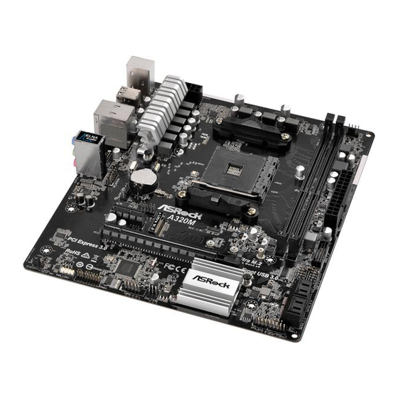
  • Seite 5 AB350M A320M A320M: CPU_FAN1 ATX12V1 USB 2.0 T: USB1 B: USB2 USB 3.0 T: USB1 B: USB2 USB 3.0 T: USB3 B: USB4 HD_AUDIO1 CMOS Battery CHA_FAN1 A320M BIOS PCIE1 Front USB 3.0 M2_1_CT2 M2_1_CT1 M2_1_CT3 Ultra M.2 PCIe Gen3 x4 PCIE2 PCI Express 3.0...
  • Seite 6 No. Description ATX 12V Power Connector (ATX12V1) 2 x 288-pin DDR4 DIMM Slots (DDR4_A1, DDR4_B1) CPU Fan Connector (CPU_FAN1) ATX Power Connector (ATXPWR1) USB 3.0 Header (USB3_7_8) USB 2.0 Header (USB_5_6) USB 2.0 Header (USB_3_4) SATA3 Connector (SATA3_3) SATA3 Connector (SATA3_4) SATA3 Connector (SATA3_2) SATA3 Connector (SATA3_1) System Panel Header (PANEL1)
  • Seite 7 AB350M A320M I/O Panel AB350M: No. Description No. Description PS/2 Mouse Port USB 3.0 Ports (USB3_56) LAN RJ-45 Port* USB 3.0 Ports (USB3_34) Line In (Light Blue)** USB 3.0 Ports (USB3_12) Front Speaker (Lime)** USB 2.0 Ports (USB_12) Microphone (Pink)**...
  • Seite 8 * There are two LEDs on each LAN port. Please refer to the table below for the LAN port LED indications. ACT/LINK LED SPEED LED LAN Port Activity / Link LED Speed LED Status Description Status Description No Link 10Mbps connection Blinking Data Activity Orange...
  • Seite 9 AB350M A320M ** To configure 7.1 CH HD Audio, it is required to use an HD front panel audio module and enable the multi- channel audio feature through the audio driver. Please set Speaker Configuration to “7.1 Speaker”in the Realtek HD Audio Manager.
  • Seite 10: Chapter 1 Introduction

    If you require technical support related to this motherboard, please visit our website for specific information about the model you are using. You may find the latest VGA cards and CPU support list on ASRock’s website as well. ASRock website http://www.asrock.com.
  • Seite 11: Specifications

    • AMD 7 Gen A-Series APUs support DDR4 2133 ECC & non-ECC, un-buffered memory* * Please refer to Memory Support List on ASRock’s website for more information. (http://www.asrock.com/) * Please refer to page 24 for DDR4 UDIMM maximum frequency support.
  • Seite 12 • 1 x PS/2 Keyboard Port • 2 x USB 2.0 Ports (Supports ESD Protection) • 6 x USB 3.0 Ports (Supports ESD Protection) (AB350M) / 4 x USB 3.0 Ports (Supports ESD Protection) (A320M) • 1 x RJ-45 LAN Port with LED (ACT/LINK LED and SPEED LED) • HD Audio Jacks: Line in / Front Speaker / Microphone...
  • Seite 13 • CPU/Chassis Fan multi-speed control • CASE OPEN detection • Voltage monitoring: +12V, +5V, +3.3V, Vcore • Microsoft® Windows® 10 64-bit * For the updated Windows® 10 driver, please visit ASRock’s web- site for details: http://www.asrock.com • FCC, CE, WHQL Certifica- • ErP/EuP ready (ErP/EuP ready power supply is required)
  • Seite 14: Chapter 2 Installation

    Chapter 2 Installation This is a Micro ATX form factor motherboard. Before you install the motherboard, study the configuration of your chassis to ensure that the motherboard fits into it. Pre-installation Precautions Take note of the following precautions before you install motherboard components or change any motherboard settings.
  • Seite 15: Installing The Cpu

    AB350M A320M 2.1 Installing the CPU Unplug all power cables before installing the CPU.
  • Seite 17 AB350M A320M 2.2 Installing the CPU Fan and Heatsink After you install the CPU into this motherboard, it is necessary to install a larger heatsink and cooling fan to dissipate heat. You also need to spray thermal grease between the CPU and the heatsink to improve heat dissipation. Make sure that the CPU and the heatsink are securely fastened and in good contact with each other.
  • Seite 19 AB350M A320M Installing the AM4 Box Cooler SR2...
  • Seite 21 AB350M A320M 4-pin FAN cable RGB LED Cable +12V *The diagram shown here are for reference only. Please refer to page 32 for the orientation of AMD Fan LED Header (AMD_FAN_LED1).
  • Seite 22 Installing the AM4 Box Cooler SR3...
  • Seite 23 AB350M A320M...
  • Seite 25 +12V Please note that only one cable should be used at a time in this step. If you select AMD_FAN_LED1, please install ASRock utility "ASRock RGB LED". If you select USB connector, please install AMD utility "SR3 Settings Software". *The diagram shown here are for reference only. Please refer to page 32 for the orientation of AMD Fan...
  • Seite 26 2.3 Installing Memory Modules (DIMM) This motherboard provides two 288-pin DDR4 (Double Data Rate 4) DIMM slots, and supports Dual Channel Memory Technology. 1. For dual channel configuration, you always need to install identical (the same brand, speed, size and chip-type) DDR4 DIMM pairs. 2.
  • Seite 27 AB350M A320M The DIMM only fits in one correct orientation. It will cause permanent damage to the motherboard and the DIMM if you force the DIMM into the slot at incorrect orientation.
  • Seite 28 2.4 Expansion Slots (PCI Express Slots) There are 2 PCI Express slots on the motherboard. Before installing an expansion card, please make sure that the power supply is switched off or the power cord is unplugged. Please read the documentation of the expansion card and make necessary hardware settings for the card before you start the installation.
  • Seite 29 AB350M A320M 2.5 Jumpers Setup The illustration shows how jumpers are setup. When the jumper cap is placed on the pins, the jumper is “Short”. If no jumper cap is placed on the pins, the jumper is “Open”. The illustration shows a 3-pin jumper whose pin1 and pin2 are “Short”...
  • Seite 30 2.6 Onboard Headers and Connectors Onboard headers and connectors are NOT jumpers. Do NOT place jumper caps over these headers and connectors. Placing jumper caps over the headers and connectors will cause permanent damage to the motherboard. System Panel Header Connect the power PLED+ PLED-...
  • Seite 31 AB350M A320M SPEAKER Chassis Intrusion and Please connect the DUMMY Speaker Header chassis intrusion and the DUMMY (7-pin SPK_CI1) chassis speaker to this (see p.1 or 3, No. 13) header. SIGNAL DUMMY Serial ATA3 Connectors These four SATA3 (SATA3_1: connectors support SATA see p.1 or 3, No.
  • Seite 32 1. High Definition Audio supports Jack Sensing, but the panel wire on the chassis must support HDA to function correctly. Please follow the instructions in our manual and chassis manual to install your system. 2. If you use an AC’97 audio panel, please install it to the front panel audio header by the steps below: A.
  • Seite 33 AB350M A320M ATX 12V Power This motherboard Connector provides a 8-pin ATX 12V (8-pin ATX12V1) power connector. To use a (see p.1 or 3, No. 1) 4-pin ATX power supply, please plug it along Pin 1 and Pin 5. RRXD1...
  • Seite 34 AMD FAN LED Header AMD FAN LED Header is used (4-pin AMD_FAN_ to connect RGB LED LED1) extension cable that comes with (see p.1 or 3, No. 21) AMD heatsink. The cable connection allows users to choose from various LED lighting effects.
  • Seite 35 AB350M A320M 2.7 M.2_SSD (NGFF) Module Installation Guide (M2_1) The M.2, also known as the Next Generation Form Factor (NGFF), is a small size and versatile card edge connector that aims to replace mPCIe and mSATA. The Ultra M.2 Socket (M2_1) supports type 2242/2260/2280 M.2 PCI Express module up to Gen3 x4 (32 Gb/s) (with Ryzen Series CPU) or Gen3 x2 (16 Gb/s) (with A-Series APU).
  • Seite 36 Step 3 Move the standoff based on the module type and length. The standoff is placed at the nut location C by default. Skip Step 3 and 4 and go straight to Step 5 if you are going to use the default nut. Otherwise, release the standoff by hand.
  • Seite 37 AB350M A320M Step 6 Tighten the screw with a screwdriver to secure the module into place. Please do not overtighten the screw as this might damage the module. NUT2 NUT1 M.2_SSD (NGFF) Module Support List Vendor Interface Intel PCIe INTEL 6000P-SSDPEKKF256G7 (nvme)
  • Seite 38 1 Einleitung Vielen Dank, dass Sie sich für das ASRock AB350M / A320M entschieden haben – ein zuverlässiges Motherboard, das konsequent unter der strengen Qualitätskontrolle von ASRock hergestellt wurde. Es liefert ausgezeichnete Leistung mit robustem Design, das ASRock Streben nach Qualität und Beständigkeit erfüllt.
  • Seite 39: Technische Daten

    • Unterstützt AMD-Sockel-AM4-APUs der A-Serie (Bristol Prozessor Ridge) und Prozessoren der Ryzen-Serie (Summit Ridge) • Digi Power design • 9-Leistungsphasendesign • Unterstützt 95-W-Luftkühlung • AMD Promontory B350 (AB350M) Chipsatz • AMD Promontory A320 (A320M) • Dualkanal-DDR4-Speichertechnologie Speicher • 2 x DDR4-DIMM-Steckplätze • CPUs von AMDs Ryzen-Serie unterstützen ungepufferten...
  • Seite 40 E/ • 2 x USB-2.0-Ports (unterstützt Schutz gegen elektrostatische Entladung) • 6 x USB-3.0-Ports (unterstützt Schutz gegen elektrostatische Entladung) (AB350M) / 4 x USB-3.0-Ports (unterstützt Schutz gegen elektrostatische Entladung) (A320M) • 1 x RJ-45-LAN-Port mit LED (Aktivität/Verbindung-LED und Geschwindigkeit-LED) • HD-Audioanschlüsse: Line-in / Vorderer Lautsprecher / Mikro-...
  • Seite 41 • ErP/EuP ready (ErP/EuP ready-Netzteil erforderlich) zierungen * Detaillierte Produktinformationen finden Sie auf unserer Webseite: http://www.asrock.com Bitte beachten Sie, dass mit einer Übertaktung, zu der die Anpassung von BIOS-Einstel- lungen, die Anwendung der Untied Overclocking Technology oder die Nutzung von Über- taktungswerkzeugen von Drittanbietern zählen, bestimmte Risiken verbunden sind.
  • Seite 42: Jumpereinstellung

    1.3 Jumpereinstellung Die Abbildung zeigt, wie die Jumper eingestellt werden. Wenn die Jumper-Kappe auf den Kontakten angebracht ist, ist der Jumper „kurzgeschlossen“. Wenn keine Jumper- Kappe auf den Kontakten angebracht ist, ist der Jumper „offen“. Die Abbildung zeigt einen 3-poligen Jumper, dessen Kontakt 1 und Kontakt 2 „kurzgeschlossen“ sind, wenn eine Jumper-Kappe auf diesen 2 Kontakten angebracht ist.
  • Seite 43: Integrierte Stiftleisten Und Anschlüsse

    AB350M A320M 1.4 Integrierte Stiftleisten und Anschlüsse Integrierte Stiftleisten und Anschlüsse sind KEINE Jumper. Bringen Sie KEINE Jumper- Kappen an diesen Stiftleisten und Anschlüssen an. Durch Anbringen von Jumper-Kappen an diesen Stiftleisten und Anschlüssen können Sie das Motherboard dauerhaft beschädi- gen.
  • Seite 44 SPEAKER Gehäuseeingriffs- und Bitte verbinden Sie Gehäu- DUMMY Lautsprecher-Stiftleiste seeingriffsvorrichtung und DUMMY (7-polig, SPK_CI1) den Gehäuselautsprecher (siehe S. 1 oder 3, Nr. 13) mit dieser Stiftleiste. SIGNAL DUMMY Serial-ATA-III-Anschlüsse Diese vier SATA-III- (SATA3_1: Anschlüsse unterstützen siehe S. 1 oder 3, Nr. 11) SATA-Datenkabel für (SATA3_2: interne Speichergeräte mit...
  • Seite 45 AB350M A320M 1. High Definition Audio unterstützt Anschlusserkennung, der Draht am Gehäuse muss dazu jedoch HDA unterstützt. Bitte befolgen Sie zum Installieren Ihres Systems die Anweisungen in unserer Anleitung und der Anleitung zum Gehäuse. 2. Bei Nutzung eines AC’97-Audiopanels dieses bitte anhand folgender Schritte an der Audiostiftleiste der Frontblende installieren: A.
  • Seite 46 ATX-12-V-Netzanschluss Dieses Motherboard bietet (8-polig, ATX12V1) einen 8-poligen ATX-12- (siehe S. 1 oder 3, Nr. 1) V-Netzanschluss. Bitte schließen Sie es zur Nut- zung eines 4-poligen ATX- Netzteils entlang Kontakt 1 und Kontakt 5 an. Serieller-Port-Stiftleiste Diese COM1-Stiftleiste RRXD1 DDTR#1 DDSR#1 (9-polig, COM1) unterstützt ein Modul für...
  • Seite 47 AB350M A320M A M D - L ü f t e r - L E D - Die AMD-Lüfter-LED-Stiftleiste Stiftleiste dient dem Anschluss des mit dem (4-polig, AMD_FAN_ AMD-Kühlkörpers gelieferten LED1) RGB-LED-Verlängerungskabels. (siehe S. 1 oder 3, Nr. 21) Der Kabelanschluss ermöglicht Nutzern die Wahl zwischen ver- schiedenen LED-Lichteffekten.
  • Seite 48: Contenu De L'emballage

    à modification sans préavis. En cas de modifications du présent document, la version mise à jour sera disponible sur le site Internet ASRock sans notifica- tion préalable. Si vous avez besoin d’une assistance technique pour votre carte mère, veuillez visiter notre site Internet pour plus de détails sur le modèle que vous utilisez.
  • Seite 49: Spécifications

    Ryzen (Summit Ridge) AM4 à socket AMD • Digi Power design • Alimentation à 9 phases • Prend en charge le refroidissement par air 95 W • AMD Promontory B350 (AB350M) Chipset • AMD Promontory A320 (A320M) • Technologie mémoire double canal DDR4 Mémoire...
  • Seite 50 • 6 x ports USB 3.0 (Protection contre les décharges électrosta- tiques) (AB350M) / 4 x ports USB 3.0 (Protection contre les décharges électrostatiques) (A320M) • 1 x port RJ-45 LAN avec LED (LED ACT/LIEN et LED VITESSE) • Connecteurs jack audio HD : Entrée ligne / haut-parleur...
  • Seite 51 Certifications • ErP/EuP Ready (alimentation ErP/EuP ready requise) * pour des informations détaillées de nos produits, veuillez visiter notre site : http://www.asrock.com Il est important de signaler que l’ o vercloking présente certains risques, incluant des modifi- cations du BIOS, l’ a pplication d’une technologie d’ o verclocking déliée et l’utilisation d’ o utils d’...
  • Seite 52 1.3 Configuration des cavaliers (jumpers) L’illustration ci-dessous vous renseigne sur la configuration des cavaliers (jumpers). Lorsque le capuchon du cavalier est installé sur les broches, le cavalier est « court- circuité ». Si le capuchon du cavalier n’ e st pas installé sur les broches, le cavalier est « ouvert ».
  • Seite 53 AB350M A320M 1.4 Embases et connecteurs de la carte mère Les embases et connecteurs situés sur la carte NE SONT PAS des cavaliers. Ne placez JAMAIS de capuchons de cavaliers sur ces embases ou connecteurs. Placer un capuchon de cavalier sur ces embases ou connecteurs endommagera irrémédiablement votre carte mère.
  • Seite 54 SPEAKER Prise DEL d’alimentation Veuillez brancher DUMMY l'emplacement sur le châssis et emplacement sur châssis DUMMY et le haut-parleur du châssis (SPK_CI1 à 7 broches) sur ce connecteur. (voir p.1 ou 3, No. 13) SIGNAL DUMMY Connecteurs Serial ATA3 Ces quatre connecteurs SATA3 sont compatibles (SATA3_1: avec les câbles de données...
  • Seite 55 AB350M A320M 1. L’ a udio haute définition prend en charge la technologie Jack Sensing (détection de la fiche), mais le panneau grillagé du châssis doit être compatible avec la HDA pour fonc- tionner correctement. Veuillez suivre les instructions figurant dans notre manuel et dans le manuel du châssis pour installer votre système.
  • Seite 56 Connecteur d’alimentation Cette carte mère est dotée d’un connecteur ATX 12V d’alimentation ATX 12V (ATX12V1 à 8 broches) à 8 broches. Pour utiliser (voir p.1 ou 3, No. 1) une alimentation ATX à 4 broches, veuillez effectuer les branchements sur la Broche 1 et la Broche 5.
  • Seite 57 AB350M A320M Embase LED de VENTI- L'embase LED de VENTILA- TEUR AMD sert à connecter LATEUR AMD le câble d'extension LED RVB (AMD_FAN_LED1 à 4 fourni avec un dissipateur broches) thermique AMD. La con- (voir p.1 ou 3, No. 21) nexion par câble permet aux...
  • Seite 58: Contenuto Della Confezione

    Nel caso di eventuali modifiche del presente manuale, la versione aggiornata sarà disponibile sul sito Web di ASRock senza ulteriore preavviso. Per il supporto tecnico correlato a questa scheda madre, visitare il nostro sito Web per informazioni specifiche relative al modello attualmente in uso.
  • Seite 59 Gen A supportano DDR4 2133 CEE e non ECC, senza buffer* * Per maggiori informazioni fare riferimento all’ e lenco dei supporti di memoria sul sito di ASRock. (http://www.asrock. com/) * Fare riferimento a pagina 24 per il supporto della frequenza massima DDR4 UDIMM.
  • Seite 60 • 2 x porte USB 2.0 (supporta protezione da scariche elettro- statiche) • 6 x porte USB 3.0 (supporta protezione da scariche elettro- statiche) (AB350M) / 4 x porte USB 3.0 (supporta protezi- (AB350M) / 4 x porte USB 3.0 (supporta protezi- 4 x porte USB 3.0 (supporta protezi- one da scariche elettrostatiche) (A320M) • 1 x porta LAN RJ-45 con LED (ACT/LINK LED e SPEED...
  • Seite 61 • ErP/EuP Ready (è necessaria alimentazione ErP/EuP ready) * Per informazioni dettagliate sul prodotto, visitare il nostro sito Web: http://www.asrock.com Prestare attenzione al potenziale rischio previsto nella pratica di overclocking, inclusa la regolazione delle impostazioni nel BIOS, l'applicazione di tecnologia di Untied Overclock- ing o l'utilizzo di strumenti di overclocking di terze parti.
  • Seite 62 1.3 Impostazione jumper L'illustrazione mostra in che modo vengono impostati i jumper. Quando il cappuccio del jumper è posizionato sui pin, il jumper è "cortocircuitato". Se sui pin non è posizionato alcun cappuccio del jumper, il jumper è "aperto". L'illustrazione mostra un jumper a 3 pin i cui pin1 e pin2 sono "cortocircuitati"...
  • Seite 63 AB350M A320M 1.4 Header e connettori sulla scheda Gli header e i connettori sulla scheda NON sono jumper. NON posizionare cappucci del jumper su questi header e connettori. Il posizionamento di cappucci del jumper su header e connettori provocherà danni permanenti alla scheda madre.
  • Seite 64 SPEAKER Collegamento altoparlante Collegare l’intrusione telaio DUMMY e intrusione telaio e l’altoparlante a questo col- a questo col- DUMMY (SPK_CI1 a 7 pin) legamento. (vedere pag. 1 o 3, n. 13) SIGNAL DUMMY Connettori Serial ATA3 Questi quattro connettori (SATA3_1: SATA3 supportano cavi vedere pag.
  • Seite 65 AB350M A320M 1. L'audio ad alta definizione supporta le funzioni Jack sensing, ma il filo del pannello sullo chassis deve supportare HDA per funzionare correttamente. Seguire le istruzioni presenti nel nostro manuale e nel manuale dello chassis per installare il sistema.
  • Seite 66 Connettore di Questa scheda madre è alimentazione ATX da 12 V dotata di un connettore (ATX12V1 a 8 pin) di alimentazione ATX da (vedere pag. 1 o 3, n. 1) 12 V a 8 pin. Per utilizzare un'alimentazione ATX a 4 pin, collegarla lungo il pin 1 e il pin 5.
  • Seite 67 AB350M A320M Collettore LED AMD FAN Il collettore LED AMD FAN (AMD_FAN_LED1 4 pin) viene utilizzato per collegare la (vedere pag. 1 o 3, n. 21) prolunga LED RGB in dotazione con dissipatore di calore AMD. Il collegamento del cavo consente agli utenti di selezionare tra vari effetti di illuminazione a LED.
  • Seite 68: Contenido Del Paquete

    ASRock sin previo aviso. Si necesita asistencia técnica relacionada con esta placa base, visite nuestro sitio web para obtener información específica sobre el modelo que esté...
  • Seite 69: Especificaciones

    ECC y no ECC DDR4 2133* * Consulte la lista de compatibilidades de memoria en el sitio web de ASRock para obtener más información. (http://www.asrock. com/) * Consulte la página 24 para conocer las frecuencias máximas com- patibles de DDR4 UDIMM.
  • Seite 70 • 6 x puertos USB 3.0 (admite protección contra descargas elec- trostáticas) (AB350M) / 4 x puertos USB 3.0 (admite protección contra descargas electrostáticas) (A320M) • 1 x puerto LAN RJ-45 con LED (LED DE ACTIVIDAD/EN- LACE y LED DE VELOCIDAD) • Conector de audio HD: Entrada de línea / Altavoz frontal /...
  • Seite 71 ErP/EuP) * Para obtener información detallada del producto, visite nuestro sitio Web: http://www.asrock.com Tenga en cuenta que hay un cierto riesgo implícito en las operaciones de aumento de la ve- locidad del reloj, incluido el ajuste del BIOS, aplicando la tecnología de aumento de veloci- dad liberada o utilizando las herramientas de aumento de velocidad de otros fabricantes.
  • Seite 72 1.3 Instalación de los puentes La instalación muestra cómo deben instalarse los puentes. Cuando la tapa de puente se coloca en los pines, el puente queda “Corto”. Si no coloca la tapa de puente en los pines, el puente queda “Abierto”. La ilustración muestra un puente de 3 pines cuyo pin 1 y pin 2 son “Cortos”...
  • Seite 73 AB350M A320M 1.4 Conectores y cabezales incorporados Los cabezales y conectores incorporados NO son puentes. NO coloque tapas de puente so- bre estos cabezales y conectores. Si coloca tapas de puente sobre los cabezales y conectores dañará de forma permanente la placa base.
  • Seite 74 SPEAKER Cabezal de intrusión de Conecte la intrusión de DUMMY chasis y el altavoz del chasis chasis y de altavoces DUMMY a este cabezal. (SPK_CI1 de 7 pines) (consulte la pág. 1 ó 3, N.º 13) SIGNAL DUMMY Conectores Serie ATA3 Estos cuatro conectores SATA3 son compatibles (SATA3_1:...
  • Seite 75 AB350M A320M 1. El Audio de Alta Definición (HDA, en inglés) es compatible con el método de sensor de conectores, sin embargo, el cable del panel del chasis deberá ser compatible con HDA para que pueda funcionar correctamente. Siga las instrucciones que se indican en nuestro manual y en el manual del chasis para instalar su sistema.
  • Seite 76 Conector de alimentación Esta placa base contiene un conector de alimentación ATX de 12V ATX de 12V y 8 pines. Para (ATX12V1 de 8 pines) utilizar una toma de ali- (consulte la pág. 1 ó 3, N.º 1) mentación ATX de 4 pines, conéctela en los Pines del 1 al 5.
  • Seite 77 AB350M A320M B ase de conexiones de La base de conexiones de LED de LED de VENTILADOR VENTILADOR AMD se utiliza para conectar el alagador de LED (AMD_FAN_LED1 de 4 RGB incluido con el disipador contactos) AMD. La conexión del cable (consulte la pág.
  • Seite 78: Комплект Поставки

    ASRock также можно найти самый последний перечень поддерживаемых VGA- карт и ЦП. Веб-сайт ASRock http://www.asrock.com. 1.1 Комплект поставки • Материнская плата ASRock AB350M / A320M (форм-фактор Micro ATX) • Краткое руководство по установке ASRock AB350M / A320M • Компакт-диск с ПО для платы ASRock AB350M / A320M • 1 экран...
  • Seite 79: Технические Характеристики

    ЦП Ridge) и ЦП серии Ryzen (Summit Ridge) под сокет AM4 • Digi Power design • Система питания 9 • Поддерживается воздушное охлаждение, 95 Вт • AMD Promontory B350 (AB350M) Чипсет • AMD Promontory A320 (A320M) • Двухканальная память DDR4 Память...
  • Seite 80 • 2 порта USB 2.0 (с защитой от электростатических разрядов) задней панели • 6 портов USB 3.0 (с защитой от электростатических разрядов) (AB350M) / 4 порта USB 3.0 (с защитой от электростатических разрядов) (A320M) • 1 порт ЛВС RJ-45 с индикаторами («Активность/ Соединение»...
  • Seite 81 • Контроль напряжений: +12 В, +5 В, +3,3 В, Vcore • Microsoft® Windows® 10 (64-разрядная) Операционные * Подробные сведения об обновлении драйвера для Win- системы dows® 10 представлены на веб-сайте ASRock:http://www. asrock.com • FCC, CE, WHQL Сертификация • Совместимость с ErP/EuP (необходим блок питания, соответствующий...
  • Seite 82 1.3 Установка перемычек Установка перемычек показана на рисунке. При установке колпачковой перемычки на контакты перемычка «замкнута». Если колпачковая перемычка на контакты не установлена, перемычка «разомкнута». На рисунке показана 3-контактная перемычка с замкнутыми контактами 1 и 2 при установке на них колпачковой...
  • Seite 83 AB350M A320M 1.4 Колодки и разъемы, расположенные на материнской плате Расположенные на материнской плате колодки и разъемы перемычками НЕ являются. НЕ устанавливайте на эти колодки и разъемы колпачковые перемычки. Установка колпачковых перемычек на эти колодки и разъемы может вызвать неустранимое повреждение материнской платы.
  • Seite 84 SPEAKER Колодка с разъемами Предназначена для DUMMY подключения датчика датчика вскрытия DUMMY вскрытия корпуса и корпуса и динамика корпусного динамика. (7-контактный, SPK_ CI1) SIGNAL (См. стр. 1 или 3, № 13) DUMMY Разъемы Serial ATA3 Эти четыре разъема SATA3 предназначены для (SATA3_1: подключения...
  • Seite 85 AB350M A320M 1. Аудиосистема высокого разрешения поддерживает функцию распознавания разъема, но для е правильной работы необходимо, чтобы провод панели корпуса поддерживал передачу сигналов HDA. Инструкции по установке системы см. в этом руководстве и руководстве на корпус. 2. При использовании аудиопанели AC’97 подключите ее к аудиоколодке передней...
  • Seite 86 Эта материнская плата Разъем питания АТХ 12 В снабжена 8-контактным (8-контактный, ATX12B1) разъемом питания АТХ (См. стр. 1 или 3, № 1) 12 В. Чтобы использовать 4-контактный разъем питания ATX, подключите его вдоль контакта 1 и контакта 5. Колодка COM1 Колодка...
  • Seite 87 AB350M A320M Колодка для Колодка для подключения светодиодной подсветки подключения вентилятора AMD светодиодной подсветки служит для подключения вентилятора AMD. удлинительного кабеля (4-контактная, AMD_ светодиодной RGB- FAN_LED1) подсветки, который (см. стр. 1 или 3, № 21) поставляется с кулером AMD. Подключив этот...
  • Seite 88: Conteúdo Da Embalagem

    1 Introdução Obrigado por adquirir a placa mãe ASRock AB350M / A320M, uma confiável placa mãe ASRock produzida sob rigoroso controle de qualidade consistente. Esta placa principal oferece um excelente desempenho com um design robusto em conformidade com o compromisso da ASRock em fabricar produtos de qualidade e resistentes.
  • Seite 89 CPUs série Ryzen (Ridge Summit) • Digi Power design • Design com 9 fases de alimentação • Suporta Refrigeração de Ar 95W • AMD Promontory B350 (AB350M) Chipset • AMD Promontory A320 (A320M) • Tecnologia de memória DDR4 de dois canais Memória...
  • Seite 90 • 2 x Portas USB 2.0 (Suporta Proteção ESD) terior • 6 x Portas USB 3.0 (Suporta Proteção ESD) (AB350M) / 4 x Portas USB 3.0 (Suporta Proteção ESD) (A320M) • 1 x Porta LAN RJ-45 com LED (LED ACT/LINK e LED DE VELOCIDADE) • Fichas de áudio HD: Entrada de Linha / Autofalante Frontal /...
  • Seite 91 • Monitoramento da tensão: +12V, +5V, +3,3V, Vcore • Microsoft® Windows® 10 64-bit * Para o driver atualizado do Windows® 10, por favor, visite o website da ASRock para mais detalhes: http://www.asrock.com • FCC, CE, WHQL Certifi- • Preparada para ErP/EuP (é necessária uma fonte de alimen- cações...
  • Seite 92 1.3 Configuração dos jumpers A imagem abaixo mostra como os jumpers são configurados. Quando a tampa do jumper é colocada nos pinos, o jumper é "Curto". Se não for colocada uma tampa de jumper nos pinos, o jumper é "Aberto". A imagem mostra um jumper de 3 pinos cujos pino1 e pino2 estão "Curtos"...
  • Seite 93 AB350M A320M 1.4 Suportes e conectores onboard Os conectores e suportes onboard NÃO são jumpers. NÃO coloque tampas de jumpers so- bre estes terminais e conectores Colocar tampas de jumpers sobre os terminais e conectores irá causar danos permanentes à placa-mãe.
  • Seite 94 SPEAKER Intrusão do Chassi e Conecte a instrusão do DUMMY chassi e autofalante do Cabeçote de Autofalante DUMMY chassia este cabeçote. (SPK_CI1 de 7 pinos) (ver p.1 ou p.3, N.º 13) SIGNAL DUMMY Conectores série ATA3 Estes quatro conectores SATA3 suportam (SATA3_1: cabos de dados SATA ver p.1 ou 3, Nº.
  • Seite 95 AB350M A320M 1. O Áudio de alta definição suporta Sensor de Adaptador, mas o fio do painel no chassi deverá suportar HDA para funcionar corretamente. Por favor, siga as instruções no nosso manual e no manual do chassi para instalar o seu sistema.
  • Seite 96 Conector de alimentação Esta placa-mãe inclui um conector de alimentação de 12V ATX de 12V ATX de 8 pinos. (ATX12V1 de 8 pinos) Para utilizar uma fonte de (ver p.1 ou p.3, N.º 1) alimentação ATX de 4 pinos, introduza-a no Pino 1 e Pino RRXD1 Suporte da porta serial Este suporte COM1 recebe...
  • Seite 97 AB350M A320M C ab eçote de LED FAN Cabeçote de LED FAN AMD é usado para conectar o cabo de (AMD_FAN_LED1 4 extensão de LED RGB que vem pinos) com dissipador de calor AMD. (ver p.1 ou p.3, N.º 21) A conexão de cabo permite aos...
  • Seite 98: Ambalaj İçeriği

    1 Giriş ASRock'ın zorlu kalite kontrol süreçlerinden geçmiş olan ASRock AB350M / A320M ana kartını satın aldığınız için teşekkür ederiz. Sağlam tasarımı ile ASRock'ın kalite ve dayanıklılık taahhüdüne uygun şekilde mükemmel performans sağlar. Ana kart özellikleri ve BIOS yazılımı güncellenebileceğinden, bu kılavuzun içeriği herhangi bir bildirimde bulunulmaksızın değiştirilebilir.
  • Seite 99 • AMD 7. Gen A Serisi APU’lar DDR4 2133 ECC ve ECC olmayan, ara belleğe alınmamış bellek destekler* * Daha fazla bilgi için lütfen ASRock’ın web sitesindeki Bellek Desteği Listesine başvurun. (http://www.asrock.com/) * Lütfen en fazla DDR4 UDIMM frekans desteği için 24. sayfaya başvurun.
  • Seite 100 • 2 tane USB 2.0 Bağlantısı Noktası (ESD Korumasını destekler) • 6 tane USB 3.0 Bağlantı Noktası (ESD Korumasını destek- ler) (AB350M) / 4 tane USB 3.0 Bağlantı Noktası (ESD Korumasını destekler) (A320M) • LED'e sahip 1 tane RJ-45 LAN Bağlantı Noktası (ACT/LINK LED ve SPEED LED) • HD Ses Girişleri/Çıkışları: Hat Girişi / Ön Hoparlör / Mikro-...
  • Seite 101 • ErP/EuP için hazır (ErP/EuP için hazır güç beslemesi gerek- lidir) * Detaylı ürün bilgisi için lütfen web sitemizi ziyaret edin: http://www.asrock.com Lütfen, BIOS ayarlarını düzenleme, Bağımsız Hız Aşırtma Teknolojisinin uygulanması veya üçüncü taraf hız aşırtma araçlarının kullanılması da dâhil olmak üzere tüm hız aşırtma işlemlerinin belirli bir risk taşıdığını...
  • Seite 102 1.3 Bağlantı Teli Kurulumu Çizim, bağlantı tellerinin kurulumunu göstermektedir. Tel kapağı, pimlerin üzerine yerleştirildiğinde, tel "Kısa" olur. Pimlerin üzerinde tel kapağı bulunmadığında, tel "Açık" olur. Çizim, pin1 ve pin2 alanları "Kısa" olan ve bu iki pim üzerinde bir bağlantı teli kapağı bulunan 3 pimli bağlantı telini göstermektedir. CMOS'u Temizle Bağlantı...
  • Seite 103 AB350M A320M 1.4 Yerleşik Bağlantılar ve Bağlayıcılar Yerleşik bağlantılar ve bağlayıcılar bağlantı teli değildir. Bağlantı teli kapaklarını bu bağlantı ve bağlayıcılar üzerine yerleştirmeyin. Bağlantı teli kapaklarının bağlantılar ve bağlayıcılar üzerine yerleştirilmesi ana karta kalıcı hasar verebilir. Sistem Paneli Bağlantısı Güç anahtarını bağlayın,...
  • Seite 104 SPEAKER Kasa Yetkisiz Erişim ve Lütfen kasa yetkisiz erişim DUMMY Hoparlör Bağlantısı ve kasa hoparlörünü bu DUMMY (7 pimli SPK_CI1) bağlantıya takın. (bkz. s.1 veya s.3, No. 13) SIGNAL DUMMY Seri ATA3 Bağlayıcıları Bu dört SATA3 bağlayıcısı, (SATA3_1: veri aktarım hızı 6,0 Gb/ bkz.
  • Seite 105 AB350M A320M 1. Yüksek Tanımlı Ses, Jak Algılama özelliğini destekler ancak bu işlevin düzgün çalışabilmesi için kasa üzerindeki panel kablosunun HDA işlevini desteklemesi gerekme- ktedir. Sisteminizi kurarken, lütfen kılavuzumuzdaki ve kasa kılavuzundaki talimatları izleyin. 2. AC'97 ses paneli kullanıyorsanız, lütfen aşağıdaki adımları uygulayarak ön panel ses bağlantısına takın:...
  • Seite 106 ATX 12V Güç Bağlayıcısı Bu ana kart, 8 pimli ATX (8 pimli ATX12V1) 12V güç bağlayıcısı sağlar. (bkz. s.1 veya s.3, No. 1) 4 pimli ATX güç beslemesi kullanmak için lütfen Pim 1 ve Pim 5'e bağlayın. Seri Bağlantı Noktası Bu COM1 bağlantısı...
  • Seite 107 AB350M A320M AMD FAN LED Bağlantısı AMD FAN LED Bağlantısı, AMD (4 pimli AMD_FAN_ Soğutucu ile gelen RGB LED LED1) uzatma kablosunu bağlamak (bkz. s.1 veya s.3, No. 21) için kullanılır. Kablo bağlantısı kullanıcıların çeşitli LED aydınlatma efektlerini seçmelerini sağlar.
  • Seite 108 1 개요 ASRock AB350M / A320M 마더보드를 구입해 주셔서 감사합니다 . 이 마더보드 는 ASRock 의 일관되고 엄격한 품질관리 하에 생산되어 신뢰성이 우수합니다 . 품질과 내구성에 대한 ASRock 의 기준에 부합하는 우수한 성능과 견고한 설계 를 제공합니다 . 마더보드 규격과 BIOS 소프트웨어를 업데이트할 수도 있기 때문에 , 이 설명서의...
  • Seite 109 • AMD 7 세대 A 시리즈 APU 는 DDR4 2133 ECC 및 비 ECC, 비버퍼링 메모리를 지원합니다 .* * 자세한 내용은 다음 ASRock 웹사이트에 있는 메모리 지원 목 록을 참조하십시오 . (http://www.asrock.com/) * DDR4 UDIMM 최대 주파수 지원은 24 페이지를 참조하십시...
  • Seite 110 • PS/2 키보드 포트 1 개 • USB 2.0 포트 2 개 (ESD 보호 지원 ) • USB 3.0 포트 6 개 (ESD 보호 지원 ) (AB350M) / USB 3.0 포트 4 개 (ESD 보호 지원 ) (A320M) • LED 장착 RJ-45 LAN 포트 1 개 (ACT/LINK LED 및 SPEED LED) •...
  • Seite 111 • FCC, CE, WHQL 인증 • ErP/EuP 사용 가능 (ErP/EuP 사용 가능 전원공급장치 필요 ) * 자세한 제품 정보에 대해서는 당사 웹사이트를 참조하십시오 : http://www.asrock.com BIOS 설정을 조정하거나 Untied Overclocking Technology 를 적용하거나 타업체의 오버클로킹 도구를 사용하는 것을 포함하는 오버클로킹에는 어느 정도의 위험이...
  • Seite 112 1.3 점퍼 설정 그림은 점퍼를 어떻게 설정하는지 보여줍니다 . 점퍼 캡을 핀에 씌우면 점퍼가 " 단락 " 됩니다 . 점퍼 캡을 핀에 씌우지 않으면 점퍼가 " 단선 " 됩니다 . 그림은 3 핀 점퍼를 보여주며 핀 1 과 핀 2 는 점퍼 캡을 씌울 때 " 단락 " 됩니다 . Clear CMOS 점퍼...
  • Seite 113 AB350M A320M 1.4 온보드 헤더 및 커넥터 온보드 헤더와 커넥터는 점퍼가 아닙니다 . 점퍼 캡을 온보드 헤더와 커넥터에 씌 우지 마십시오 . 점퍼 캡을 온보드 헤더와 커넥터에 씌우면 마더보드가 영구적으 로 손상됩니다 . 시스템 패널 헤더 섀시의 전원 스위치 , 리...
  • Seite 114 SPEAKER 섀시 침입 및 스피커 헤더 섀시 침입 및 섀시 스피 DUMMY (7 핀 SPK_CI1) 커를 이 헤더에 연결하 DUMMY (1 또는 3 페이지 , 13 번 참조 ) 십시오 . SIGNAL DUMMY 시리얼 ATA3 커넥터 이들 네 개의 SATA3 커 넥터는...
  • Seite 115 AB350M A320M 1. 고음질 오디오는 잭 감지를 지원하지만 올바르게 작동하려면 섀시의 패널 와이 어가 HDA 를 지원해야 합니다 . 설명서 및 섀시 설명서에 나와 있는 지침을 따 라 시스템을 설치하십시오 . 2. AC’ 97 오디오 패널을 사용할 경우 아래와 같은 절차를 따라 전면 패널 오디오...
  • Seite 116 ATX 12V 전원 커넥터 이 마더보드에는 8 핀 (8 핀 ATX12V1) ATX 12V 전원 커넥터가 (1 또는 3 페이지 , 1 번 참 탑재되어 있습니다 . 4 핀 조 ) ATX 전원공급장치를 사 용하려면 핀 1 과 핀 5 을 따라...
  • Seite 117 AB350M A320M AMD 팬 LED 헤더 AMD 팬 LED 헤더는 AMD 방열 (4 핀 AMD_FAN_LED1) 판과 함께 제공되는 RGB LED (1 또는 3 페이지 , 21 번 연장 케이블을 연결하는 데 사 항목 참조 ) 용됩니다 . 케이블 연결에서 사...
  • Seite 118 さい。 ASRock のウェブサイ トでは、 最新の VGA カードおよび CPU サポート一覧も ご覧になれます。 ASRock ウェブサイ ト http://www.asrock.com. 1.1 パッケージの内容 • ASRock AB350M / A320M マザーボード (マイクロ ATX フォームファクター) • ASRock AB350M / A320M クイックインストールガイ ド • ASRock AB350M / A320M サポート CD • 1 x I/O パネルシールド...
  • Seite 119 び Ryzen シリーズ CPU (Summit Ridge) に対応 • デジタル電源設計 • 9 電源フェーズ設計 • 95W の空冷に対応 チップセッ ト • AMD Promontory B350 (AB350M) • AMD Promontory A320 (A320M) • デュアルチャンネル DDR4 メモリテク ノロジー メモリ • 2 x DDR4 DIMM スロッ ト...
  • Seite 120 • 2 x USB 2.0 ポート (静電気放電 (ESD) 保護に対応) • 6 x USB 3.0 ポート (静電気放電 (ESD) 保護に対応) (AB350M) / 4 x USB 3.0 ポート (静電気放電 (ESD) 保護に 対応) (A320M) • LED 付き 1 x RJ-45 LAN ポート (ACT/LINK LED と...
  • Seite 121 • CPU/ シャーシ静音ファン • CPU/ シャーシファンマルチ速度制御 • ケース開閉検知 • 電圧監視 : +12V、 +5V、 +3.3V、 Vcore • Microsoft® Windows® 10 64-bit * 更新された Windows® 10 ドライバについては、 ASRock のウ ェブサイ トで詳細をご確認く ださい :http://www.asrock.com 認証 • FCC、 CE、 WHQL • ErP/EuP Ready ( ErP/EuP 対応電源供給装置が必要です)...
  • Seite 122 1.3 ジャンパー設定 このイラストは、 ジャンパーの設定方法を示しています。 ジャンパーキャップがピ ンに被さっていると、 ジャンパーは 「ショート」 です。 ジャンパーキャップがピンに被 さっていない場合には、 ジャンパーは 「オープン」 です。 この図は 3ピンのジャンパー を表し、 ジャンパーキャップがピン 1 とピン 2 に被さっているとき、 これらのピンは 「ショート」 です。 CMOS クリアジャンパー (CLRMOS1) デフォルト CMOS のク リア (p.1 または 3、 No. 18 参照) CLRMOS1 を使って CMOS 内のデータをクリアできます。 ク リアして、 デフォルト 設定にシステムパラメーターをリセッ...
  • Seite 123 AB350M A320M 1.4 オンボードのヘッダーとコネクター オンボードヘッダーとコネクターはジャンパーではありません。 これらヘッダーとコ ネクターにはジャンパーキャップを被せないでく ださい。 ヘッダーおよびコネクター にジャンパーキャップを被せると、 マザーボードに物理損傷が起こるこ とがあります。 システムパネルヘッダー 電源スイッチを接続し、 PLED+ PLED- (9 ピンパネル 1) スイッチをリセッ トし、 下 PWRBTN# (p.1 または 3、 No. 12 参照) 記のピン割り当てに従っ て、 シャーシのシステムス テータス表示ランプをこ RESET# HDLED- のヘッダーにセッ トしま HDLED+ す。 ケーブルを接続する...
  • Seite 124 シャーシイントルージョン SPEAKER シャーシイントルージョン DUMMY とスピーカーヘッダー とシャーシスピーカーを DUMMY (7 ピン SPK_CI1) このヘッダーに接続して (p.1 または 3、 No. 13 参照) く ださい。 SIGNAL DUMMY シリアル ATA3 コネクタ これら 4 つの SATA3 コネ ー クターは、 最高 6.0 Gb/ 秒 のデータ転送速度で内部 (SATA3_1: p.1 または 3、 No. 11 参照) ストレージデバイス用の...
  • Seite 125 AB350M A320M 1. ハイディフィニションオーディオはジャックセンシングをサポートしていますが、 正しく機能するためには、 シャーシのパネルワイヤーが HDA をサポートしている こ とが必要です。 お使いのシステムを取り付けるには、 当社のマニュアルおよび シャーシのマニュアルの指示に従ってく ださい。 2. AC 97 オーディオパネルを使用する場合には、 次のステップで、 前面パネルオー ディオヘッダーに取り付けてく ださい。 A. Mic_IN (MIC) を MIC2_L に接続します。 B. Audio_R (RIN) を OUT2_R に、 Audio_L (LIN) を OUT2_L に接続します。 C. アース (GND) をアース (GND) に接続します。...
  • Seite 126 ATX 12V 電源コネクター このマザーボードは 8 ピ (8 ピン ATX12V1) ン ATX12V 電源コネク (p.1 または 3、 No. 1 参照) ターが装備されていま す。 4 ピンの ATX 電源を 使用するには、 ピン 1 と 5 番に合わせて接続してく ださい。 シリアルポートヘッダー この COM1 ヘッダーはシ RRXD1 DDTR#1 (9 ピン COM1) DDSR#1 リアルポートモジュール...
  • Seite 127 AB350M A320M AMD ファン LED ヘッ AMD ファン LED ヘッダーを使 ダー 用して AMD ヒートシンクに付属 (4 ピン AMD_FAN_ している RGB LED 延長ケーブ ルを接続します。 ケーブルを接 LED1) (p.1 または 3、 No. 21 参照) 続すれば、 ユーザーはさまざま な LED ライティ ング効果を選択 できます。 注意 : ファン LED ケーブルは間...
  • Seite 128 我们不会另外进行通知。 如果您需要与此主板相关的技术支持,请访问我们的 网站以具体了解所用型号的信息。 您也可以在华擎网站上找到最新 VGA 卡和 CPU 支持列表。 华擎网站 http://www.asrock.com。 1.1 包装清单 • 华擎 AB350M / A320M 主板(Micro ATX 规格尺寸) • 华擎 AB350M / A320M 快速安装指南 • 华擎 AB350M / A320M 支持光盘 • 1 x I/O 面板 • 2 x 串行 ATA (SATA) 数据线(选购)...
  • Seite 129 • 支持 AMD Socket AM4 A 系列 APU (Bristol Ridge) 和锐 龙 AMD Ryzen 处理器(Summit Ridge) • Digi Power design • 9 电源相设计 • 支持 95W 风冷散热 • AMD Promontory B350 (AB350M) 芯片集 • AMD Promontory A320 (A320M) • 双通道 DDR4 内存技术 内存...
  • Seite 130 • 1 x PS/2 键盘端口 • 2 x USB 2.0 端口 ( 支持 ESD 保护 ) • 6 x USB 3.0 端口 ( 支持 ESD 保护 ) (AB350M) / 4 x USB 3.0 端口 ( 支持 ESD 保护 )(A320M) • 1 x RJ-45 LAN 端口,带 LED(ACT/LINK LED 和 SPEED LED)...
  • Seite 131 • CPU/ 机箱风扇多种速度控制 • CASE OPEN(机箱打开)检测 • 电压监控: +12V、+5V、+3.3V、Vcore • Microsoft® Windows® 10 64-bit 操作系统 * 有关已更新的 Windows® 10 驱动程序,请访问华擎网站了解 详情 :http://www.asrock.com • FCC、CE、WHQL 认证 • ErP/EuP 支持(需要支持 ErP/EuP 的电源) * 有关详细产品信息,请访问我们的网站: http://www.asrock.com 须认识到超频会有一定风险,包括调整 BIOS 设置,应用“自由超频技术”,或 使用第三方超频工具。 超频可能会影响到系统的稳定性,甚至对系统的组件和 设备造成损坏。 执行这项工作您应自担风险和自己承担费用。 我们对由于超频 而造成的损坏概不负责。...
  • Seite 132 1.3 跳线设置 此图显示如何设置跳线。 将跳线帽装到这些针脚上时,跳线 “短接”。 如果 这些针脚上没有装跳线帽,跳线 “开路”。 此图显示 3 针跳线,当跳线帽装在 针脚 1 和针脚 2 上,它们“短接”。 清除 CMOS 跳线 (CLRMOS1) 默认 清除 CMOS (参见第 1 页或第 3 页, 第 18 个) CLRMOS1 允许您清除 CMOS 中的数据。 要清除和重置系统参数到默认设 置,请关闭计算机,从电源上拔下电源线插头。 等候 15 秒后,使用跳线帽将 CLRMOS1 上的针脚...
  • Seite 133 AB350M A320M 1.4 板载接脚和接口 板载接脚和接口不是跳线。 不要将跳线帽装到这些接脚和接口上。 将跳线帽装 到这些接脚和接口上将会对主板造成永久性损坏。 系统面板接脚 按照下面的针脚分配, PLED+ PLED- (9 针 PANEL1) 将机箱上的电源开关、 PWRBTN# (参见第 1 页或第 3 页, 重置开关和系统状态指 第 12 个) 示灯连接到此接脚。 在 RESET# 连接线缆前请记下正负 HDLED- 针脚。 HDLED+ PWRBTN(电源开关): 连接到机箱前面板上的电源开关。 您可以配置使用电源开关关闭系统的方式。 RESET(重置开关): 连接到机箱前面板上的重置开关。 如果计算机死机,无法执行正常重新启动, 按重置开关重新启动计算机。...
  • Seite 134 串行 ATA3 接口 这四个 SATA3 接口支持 最高 6.0 Gb/s 数据传输 (SATA3_1: 参见第 1 页或第 3 页, 速率的内部存储设备的 第 11 个) SATA 数据线。 (SATA3_2: 参见第 1 页或第 3 页, 第 10 个) (SATA3_3: 参见第 1 页或第 3 页, 第 8 个) (SATA3_4: 参见第...
  • Seite 135 AB350M A320M 1. 高清音频支持插孔感测,但机箱上的面板连线必须支持 HDA 才能正常工作。 请按照我们的手册和机箱手册的说明安装系统。 2. 如果您使用 AC’97 音频面板,请按照以下步骤将它安装到前面板音频接脚: A. 将 Mic_IN (MIC) 连接到 MIC2_L。 B. 将 Audio_R (RIN) 连接到 OUT2_R,将 Audio_L (LIN) 连接到 OUT2_L。 C. 将接地端 (GND) 连接到接地端 (GND)。 D. MIC_RET 和 OUT_RET 只用于高清音频面板。 您不需要针对 AC’97 音频...
  • Seite 136 ATX 12V 电源接口 此主板提供 8 针 ATX (8 针 ATX12V1) 12V 电源接口。 要使用 4 (参见第 1 页或第 3 页, 针 ATX 电源,请沿针脚 第 1 个) 1 和针脚 5 插接它。 串行端口接脚 此 COM1 接脚支持串行 RRXD1 DDTR#1 DDSR#1 (9 针 COM1) 端口模块。 CCTS#1 (参见第...
  • Seite 137 AB350M A320M AMD 风扇 LED 接脚 AMD 风扇 LED 接脚用于连接 (4 针 AMD_FAN_LED1) AMD 散热器附带的 RGB LED (参见第 1 页或第 3 页, 延长线。 连接线缆可以让用户 第 21 个) 选择不同的 LED 灯光效果。 注意: 风扇 LED 线安装方向切 勿错误,否则,线缆会损坏。...
  • Seite 138 电子信息产品污染控制标示 依据中国发布的「电子信息产品污染控制管理办法」及 SJ/T 11364-2006「电子 信息产品污染控制标示要求」,电子信息产品应进行标示,藉以向消费者揭露 产品中含有的有毒有害物质或元素不致发生外泄或突变从而对环境造成污染或 对人身、财产造成严重损害的期限。依上述规定,您可于本产品之印刷电路板 上看见图一之标示。图一中之数字为产品之环保使用期限。由此可知此主板之 环保使用期限为 10 年。 图一 有毒有害物质或元素的名称及含量说明 若您欲了解此产品的有毒有害物质或元素的名称及含量说明,请参照以下表格 及说明。 有害物质或元素 部件名称 铅 (Pb) 镉 (Cd) 汞 (Hg) 六价铬 (Cr(VI)) 多溴联苯 (PBB) 多溴二苯醚 (PBDE) 印刷电路板 及电子组件 外部信号连 接头及线材 O: 表示该有毒有害物质在该部件所有均质材料中的含量均在 SJ/T 11363-2006 标准规定 的限量要求以下。 X: 表示该有毒有害物质至少在该部件的某一均质材料中的含量超出 SJ/T 11363-2006 标准 规定的限量要求,然该部件仍符合欧盟指令...
  • Seite 139 您需要與本主機板相關的技術支援,請上我們的網站瞭解有關您使用機型的特 定資訊。 您也可以在華擎網站找到最新的 VGA 卡及 CPU 支援清單。 華擎網站 http://www.asrock.com。 1.1 包裝內容 • 華擎 AB350M / A320M 主機板(Micro ATX 尺寸) • 華擎 AB350M / A320M 快速安裝指南 • 華擎 AB350M / A320M 支援光碟 • 1 x I/O 面板外罩 • 2 x Serial ATA (SATA) 資料纜線(選用)...
  • Seite 140 • 支援 AMD Socket AM4 A 系列 APU (Bristol Ridge) 與 Ryzen 系列 CPU (Summit Ridge) • Digi Power design • 9 電源相位設計 • 支援 95W 風冷 • AMD Promontory B350 (AB350M) 晶片組 • AMD Promontory A320 (A320M) • 雙通道 DDR4 記憶體技術 記憶體...
  • Seite 141 • 1 x PS/2 滑鼠連接埠 後面板 I/O • 1 x PS/2 鍵盤連接埠 • 2 x USB 2.0 連接埠(支援靜電保護) • 6 x USB 3.0 連接埠(支援靜電保護)(AB350M) / 4 x USB 3.0 連接埠(支援靜電保護)(A320M) • 1 x RJ-45 LAN 連接埠,含 LED(ACT/LINK LED 及 SPEED LED)...
  • Seite 142 • CPU /機殼風扇多重速度控制 • 機殼開啟偵測 • 電壓監控: +12V、+5V、+3.3V、Vcore • Microsoft® Windows® 10 64-bit 作業系統 * 關於最新 Windows® 10 驅動程式的詳細資訊,請瀏覽華擎網 站:http://www.asrock.com • FCC、CE、WHQL 認證 • ErP/EuP ready(須具備 ErP/EuP ready 電源供應器) * 如需產品詳細資訊,請上我們的網站: http://www.asrock.com 請務必理解,超頻可能產生某種程度的風險,其中包括調整 BIOS 中的設定、採 用自由超頻技術或使用協力廠商的超頻工具。 超頻可能會影響您系統的穩定性, 或者甚至會對您系統的元件及裝置造成傷害。 您應自行負擔超頻風險及成本。 我們對於因超頻所造成的可能損害概不負責。...
  • Seite 143 AB350M A320M 1.3 跳線設定 圖例顯示設定跳線的方式。 當跳線帽套在針腳上時,該跳線為「短路」。 若 沒有跳線帽套在針腳上,該跳線為「開啟」。 圖例顯示當 3-pin 跳線的跳線蓋 套在 pin1 及 pin2 時,這兩個針腳皆為「短路」。 清除 CMOS 跳線 (CLRMOS1) 預設 清除 CMOS (請參閱第 1 頁或第 3 頁,編號 18) 您可利用 CLRMOS1 清除 CMOS 中的資料。 若要清除及重設系統參數為預設 設定,請先關閉電腦電源,再拔下電源供應器的電源線。 在等待 15 秒後, 請使用跳線帽讓 CLRMOS1 上的 pin2 及 pin3 短路約 5 秒。 不過,請不要在更...
  • Seite 144 1.4 板載排針及接頭 板載排針及接頭都不是跳線。 請勿將跳線帽套在這些排針及接頭上。 將跳線帽 套在排針及接頭上,將造成主機板永久性的受損。 系統面板排針 請依照以下的針腳排列 PLED+ PLED- 將機殼上的電源開關、 (9-pin PANEL1) PWRBTN# (請參閱第 1 頁或第 3 重設開關及系統狀態指 頁,編號 12) 示燈連接至此排針。 在 RESET# 連接纜線之前請注意正 HDLED- 負針腳。 HDLED+ PWRBTN ( 電源開關 ): 連接至機殼前面板上的電源開關。 您可設定使用電源開關關閉系統電源的方式。 RESET ( 重設開關 ): 連接至機殼前面板上的重設開關。 若電腦凍結且無法執行正常重新啟動,按下 重設開關即可重新啟動電腦。...
  • Seite 145 AB350M A320M Serial ATA3 接頭 這四組 SATA3 接頭皆支 援內部儲存裝置的 SATA (SATA3_1: 請參閱第 1 頁或第 3 頁, 資料纜線,最高可達 6.0 編號 11) Gb/s 資料傳輸率。 (SATA3_2: 請參閱第 1 頁或第 3 頁, 編號 10) (SATA3_3: 請參閱第 1 頁或第 3 頁, 編號 8) (SATA3_4: 請參閱第 1 頁或第 3 頁,...
  • Seite 146 1. 高解析度音訊支援智慧型音效介面偵測 (Jack Sensing),但機殼上的面板線必須 支援 HDA 才能正確運作。 請依本手冊及機殼手冊說明安裝系統。 2. 若您使用 AC’97 音訊面板,請按照以下步驟安裝至前面板音訊排針: A. 將 Mic_IN (MIC) 連接至 MIC2_L。 B. 將 Audio_R (RIN) 連接至 OUT2_R 且將 Audio_L (LIN) 連接至 OUT2_L。 C. 將接地 (GND) 連接至接地 (GND)。 D. MIC_RET 及 OUT_RET 僅供 HD 音訊面板使用。 您不需要在 AC’97 音訊 面板上連接。...
  • Seite 147 AB350M A320M ATX 12V 電源接頭 本主機板配備一組 8-pin ATX 12V 電源接頭。 若 (8-pin ATX12V1) (請參閱第 1 頁或第 3 要使用 4-pin ATX 電源 頁,編號 1) 供應器,請插入 Pin 1 及 Pin 5。 序列連接埠排針 此 COM1 排針支援序列 RRXD1 DDTR#1 DDSR#1 連接埠模組。 (9-pin COM1) CCTS#1 (請參閱第...
  • Seite 148 AMD FAN LED 排針 AMD FAN LED 排針用於連接 AMD 散熱器隨附的 RGB LED (4-pin AMD_FAN_LED1) ( 請 參 閱 第 1 頁 或 第 3 延長線。 纜線連接允許使用者 頁,編號 21) 選擇各種 LED 照明效果。 警告: 切勿以錯誤方向安裝 FAN LED 纜線,否則纜線可能 損壞。...
  • Seite 149 • Mendukung Soket AMD APU Seri AM4 A (Bristol Ridge) dan CPU Seri Ryzen (Summit Ridge) • Digi Power design • Desain 9 Fase Daya • Mendukung Pendingin Udara 95W • Promontory B350 AMD (AB350M) Chipset • Promontory A320 AMD (A320M) • Teknologi Memori DDR4 Dua Kanal Memori • 2 x Slot DIMM DDR4...
  • Seite 150 • 2 x Port USB 2.0 (Mendukung Perlindungan dari ESD) • 6 x Port USB 3.0 (Mendukung Perlindungan dari ESD) (AB350M) / 4 x Port USB 3.0 (Mendukung Perlindungan dari ESD) (A320M) • 1 x Port LAN RJ-45 dengan LED (LED ACT/LINK dan LED SPEED) • Soket Audio HD: Saluran Masuk/Speaker Depan/Mikrofon...
  • Seite 151 Sertifikasi • Siap untuk ErP/EuP (memerlukan catu daya untuk siap ErP/EuP) * Untuk informasi rinci tentang produk, kunjungi situs web kami: http://www.asrock.com Perlu diketahui, overclocking memiliki risiko tertentu, termasuk menyesuaikan pengaturan pada BIOS, menerapkan Teknologi Untied Overclocking, atau menggunakan alat bantu overclocking pihak ketiga. Overclocking dapat mempengaruhi stabilitas sistem, atau bahkan mengakibatkan kerusakan komponen dan perangkat sistem.
  • Seite 152: Contact Information

    Contact Information If you need to contact ASRock or want to know more about ASRock, you’re welcome to visit ASRock’s website at http://www.asrock.com; or you may contact your dealer for further information. For technical questions, please submit a support request form at http://www.asrock.com/support/tsd.asp...
  • Seite 153: Ec Declaration Of Conformity

    EC-Declaration of Conformity For the following equipment: Motherboard (Product Name) AB350M / A320M / ASRock (Model Designation / Trade Name) ASRock Incorporation (Manufacturer Name) 2F., No.37, Sec. 2, Jhongyang S. Rd., Beitou District, Taipei City 112, Taiwan (R.O.C.) (Manufacturer Address)

Diese Anleitung auch für:

A320m

Inhaltsverzeichnis