Werbung
Quicklinks
V3IS00262-011-022012
Vemer S.p.A.
I - 32032 Feltre (BL) • Via Camp Lonc, 16
Tel +39 0439 80638 • Fax +39 0439 80619
e-mail: info@vemer.it - web site: www.vemer.it
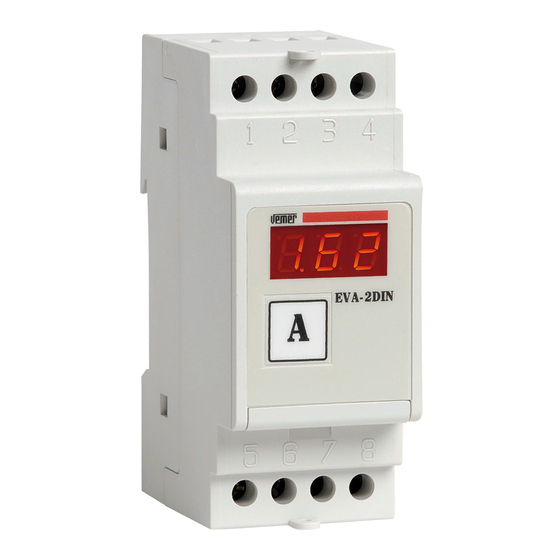
EVS-2DIN (A)
1
2
3
4
EVS-2DIN
A
Switch
5
6
7
8
35
60
EVS-4DIN (A)
1
2
3
4
5
6
7
8
9
EVS-4DIN
A
Switch
10 11 12 13 14 15 16 17 18
60
70
65
EVS-R (A)
EVS-R
A
Switch
5
72
75
(C)
ON
1 2 3 4
1
2
3
4
1
2
3
4
5
6
7
8
9
0FF
1 2 3 4
5
1
EVS-2DIN
A
EVS-4DIN
A
Switch
Switch
10 11 12 13 14 15 16 17 18
5
6
7
8
EVS-2DIN (B)
~
~
1
2
3
4
A
+
5
6
7
8
x/60 mV
EVS-4DIN (B)
x/60 mV
~
~
1
2
3
4
5
6
7
8
9
+
A
10
11
12
13
14
15
16
17
18
EVS-R (B)
x/60 mV
~
~
6
5
4
3
2
1
+
A
14
ON
OFF
ON
5
Scala
0FF
150
1 2 3 4
5
200
250
1
400
EVS-R
500
A
600
Switch
800
999
Manuale d'Uso
EVS-2DIN
Mod.
AMPEROMETRI DIGITALI
EVS-4DIN
Mod.
Leggere attentamente tutte le istruzioni
EVS-R
Mod.
AVVERTENZE DI SICUREZZA
D urante l'installazione ed il funzionamento dello strumento è necessario attenersi alle
seguenti prescrizioni:
Selezione Punto
1) I l prodotto deve essere installato da personale qualificato
Decimale (C1)
2) L eggere attentamente le istruzioni riportate in questo manuale
3) S eguire scrupolosamente gli schemi di collegamento per installare l'apparecchio
OFF
ON
4) P rima di accedere ai morsetti di collegamento accertarsi che i conduttori da collegare
o già collegati allo strumento non siano in tensione
1 2 3 4
5
Scala
5) A ssicurarsi che il quadro elettrico nel quale è inserito l'apparecchio sia tale da
9,99
garantire, dopo l'installazione, l'inaccessibilità dei morsetti
6) N on alimentare l'apparecchio se qualche parte di esso risulta danneggiata
99,9
7) L o strumento deve essere installato e messo in funzione in conformità con la
normativa vigente in materia di impianti elettrici
999
8) L o strumento è destinato all'installazione in ambienti con categoria di sovratensione
III e grado di inquinamento 2 (CEI EN 61010-1).
(D)
EVS-2DIN
OFF
ON
Codice
Modello
VM256500
EVS-2DIN
1 2 3 4
5
Scala
A kA
EVS-4DIN
5
Codice
Modello
A
10
VM268000
EVS-4DIN
A
15
EVS-R
A
20
Codice
Modello
VM322500
EVS-R
A
25
CARATTERISTICHE TECNICHE
A
40
A
50
•
Alimentazione: 115/230 V AC (-15%/+10%) 50/60 Hz
•
Lettura: 3 cifre a LED, 7 segmenti h = 7,62 mm per ogni cifra
A
60
•
Assorbimento: 5 VA
A
— Precisione: ±(0,5% f.s. +1 dgt)
100
•
Inserzione:
A
150
— amperometrica: x/60 mV su SHUNT
Fondo scala selezionabile (vedi riquadro D)
•
A
200
•
Sovraccarico massimo ammissibile:
A
— amperometrica: 1,2 I N DC permanente
250
•
Minime grandezze misurate: 4% del fondo scala
A
400
•
Terminazione: su massello da 6 mm
•
Temperatura di funzionamento: -10 °C ÷ +50 °C
A
500
•
Temperatura di immagazzinamento: -40 °C ÷ +90 °C
A
•
Umidità relativa: 20%÷90% RH non condensante
600
•
Isolamento: circuito di alimentazione e di misura isolati galvanicamente a
A
800
livello di isolamento principale (CEI EN 61010-1)
•
Contenitore:
A
1000
— EVS-2DIN: 2 moduli DIN
kA
— EVS-4DIN: 4 moduli DIN
1,50
— EVS-R: dimensioni normalizzate 72x72 mm
kA
2,00
Legenda:
kA
2,50
A) Dimensioni
kA
4,00
B) Schemi di collegamento
C) Impostazione Dip Switch
D) Fondo scala selezionabile
FUNZIONAMENTO
1) Impostare i dip-switch secondo quanto riportato nel riquadro "C"; la selezione avviene
tramite 5 switches: i primi 3 selezionano le 8 scale disponibili, gli altri 2 selezionano il
posizionamento del punto decimale
2) Collegare lo strumento secondo lo schema riportato nel riquadro "B"
Attenzione!
Non selezionare i dip-switch quando lo strumento è collegato (alimentazione e/o misura)
3) All'accensione viene visualizzata con una ripetizione di 3 intermittenze la portata selezionata:
a) se la portata è quella desiderata l'installazione è terminata;
b) se la portata non è quella desiderata, scollegare lo strumento e ripartire con la
procedura dal punto 1)
c) se è visualizzato "600." o "Err", la selezione dei dip-switch è errata, per cui bisogna
scollegare lo strumento e ripartire con la procedura dal punto 1)
4) Se, durante il funzionamento, lo strumento visualizza "HHH" vuol dire che la grandezza
in esame è superiore al valore massimo ammissibile.
5) Se la grandezza in esame è inferiore al 4% del fondo scala il display visualizza "000"
NORME ARMONIZZATE DI RIFERIMENTO
La conformità alle Direttive Comunitarie
2006/95/CE (Bassa tensione - LVD)
2004/108/CE (Compatibilità elettromagnetica - EMC)
è dichiarata in riferimento alla seguente Norma Armonizzata:
EN 61010-1
EN 61000-6-2
EN 61000-6-4
SAFETY WARNINGS
D uring the installation and operation of the instrument, the following safety
instructions should be followed:
1) T he instrument should be installed by qualified personnel
2) Read the instructions in this manual carefully
3) C arefully follow the instruction diagrams to install the device
4) B efore gaining access to the connector terminals, make sure the conductors to be
connected to the instrument or already connected are not powered
5) M ake sure the electric panel in which the device is inserted will prevent access to
the terminals after installation
6) D o not supply power to the device if any part of it is damaged
7) T he instrument must be installed and activated in compliance with current electric
systems standards
8) T he instrument is designed to be installed in locations with overvoltage category III
and pollution level 2 (EN 61010-1).
EVS-2DIN
Descrizione
Code
Amperometro multiscala DC
VM256500
EVS-4DIN
Descrizione
Code
VM268000
Amperometro multiscala DC
EVS-R
Descrizione
Code
Amperometro multiscala DC
VM322500
TECHNICAL SPECIFICATIONS
•
Power supply: 115/230 V AC (-15%/+10%) 50/60 Hz
•
Reading: 3 display digits, 7 segments h = 7,62 mm for each digit
•
Absorption: 5 VA
— Precision: ±(0,5% and of scale + 1 dgt)
•
Insertion:
— ammeter: x/60 mV on SHUNT
Scale available for selection (see panel D)
•
•
Maximum admissible overload:
— ammeter: 1,2 I N DC permanent
•
Minimum values measured: 4% end of scale
2
•
Termination: on 6 mm
•
Operating temperature: -10 °C ÷ +50 °C
•
Storage temperature: -40 °C ÷ +90 °C
•
Relative humidity: 20%÷90% RH non condensing
•
Insulation: power supply and measurement circuit galvanically insulated at main
insulation level (EN 61010-1)
•
Container:
— EVS-2DIN: 2 module DIN
— EVS-4DIN: 4 module DIN
— EVS-R: standardised dimensions 72x72 mm
Legend:
A) Dimensions
B) Connection diagrams
C) Dip Switch setting
D) End scale selectionable
OPERATION
1) Set the dip switches as instructed in panel "C" switches are used for the selection.
The first 3 select the 8 scales available, and the other 2 select the position of the
decimal point
2) Connect the instrument as shown in the diagram in panel "B"
Important!
Do not select the dip switches when the instrument is connected
(power supply and/or measurement)
3) When the instrument is switched on, the capacities selected are displayed with 3 intermittent
repetitions:
a) If the capacity is as required, the installation is complete;
b) If the capacity is not as required, disconnect the instrument and start the procedure again
from point 1)
c) If "600." or "Err" displayed, the dip switch selection
is incorrect. Disconnect the instrument and repeat the procedure from point 1)
4) If the display shows "HHH" during operation, this means that the dimension under
examination is greater than the maximum value admissible.
5) If the value in question is less than 4% of the scale, the display will show "000"
REFERENCE STANDARDS
Compliance to the Community Directives:
2006/95/EC (Low Voltage - LVD)
2004/108/EC (Electromagnetic compatibility- EMC)
is declared with reference to the follow Harmonised Standard:
EN 61010-1
EN 61000-6-2
EN 61000-6-4
User Manual
DIGITAL AMMETERS
Read all the instructions carefully
Model
Description
EVS-2DIN
DC ammeter multiscale
Model
Description
EVS-4DIN
DC ammeter multiscale
Model
Description
EVS-R
DC ammeter multiscale
2
block
Werbung

Verwandte Anleitungen für Vemer EVS-2DIN

Inhaltszusammenfassung für Vemer EVS-2DIN
- Seite 1 Vemer S.p.A. Mod. I - 32032 Feltre (BL) • Via Camp Lonc, 16 AVVERTENZE DI SICUREZZA SAFETY WARNINGS Tel +39 0439 80638 • Fax +39 0439 80619 e-mail: info@vemer.it - web site: www.vemer.it D urante l’installazione ed il funzionamento dello strumento è necessario attenersi alle D uring the installation and operation of the instrument, the following safety instructions should be followed: seguenti prescrizioni: EVS-2DIN (A)
- Seite 2 • Contenedor: • Boîtier: isoliert (EN 61010-1) — EVS-2DIN: 2 módulos DIN — EVS-2DIN: version à 2 modules DIN • Gehäuse: — EVS-4DIN: 4 módulos DIN — EVS-4DIN: version à 4 modules DIN — EVS-2DIN: 2 DIN-Modulen — EVS-R: dimensiones normalizades 72x72 mm —...