Thermon Terminator ECM-P-XP Installationsanweisung
Electronic control module/for connection (1-2 heating cables) applications
TM
Terminator
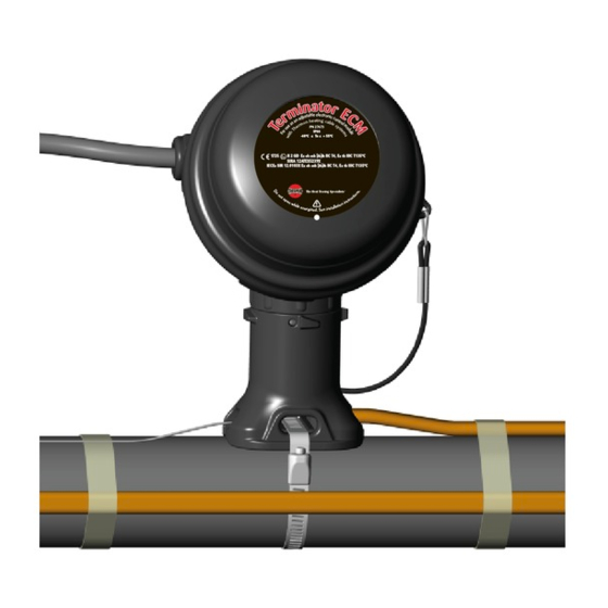
ECM-P-XP
Electronic Control Module
INSTALLATION PROCEDURES
For Connection (1-2 Heating Cables) Applications
PN 27673
IP66
-60°C ≤ Ta ≤ + 55°C
1725
II 2 GD Ex eb mb [ib]ib IIC T4, Ex tb IIIC T135°C
SIRA 12ATEX5239X
IECEx SIR 12.0103X Ex eb mb [ib]ib IIC T4, Ex tb IIIC T135°C
The Heat Tracing Specialists
®
Inhaltsverzeichnis

Verwandte Anleitungen für Thermon Terminator ECM-P-XP

Inhaltszusammenfassung für Thermon Terminator ECM-P-XP
- Seite 1 Terminator ECM-P-XP Electronic Control Module INSTALLATION PROCEDURES For Connection (1-2 Heating Cables) Applications PN 27673 IP66 -60°C ≤ Ta ≤ + 55°C 1725 II 2 GD Ex eb mb [ib]ib IIC T4, Ex tb IIIC T135°C SIRA 12ATEX5239X IECEx SIR 12.0103X Ex eb mb [ib]ib IIC T4, Ex tb IIIC T135°C The Heat Tracing Specialists ®...
-
Seite 2: Installation Procedures
INSTALLATION PROCEDURES Receiving, Storing and Handling . . . The following installation procedures are suggested guidelines for the installation of the Terminator ECM-P-XP Kit. 1. Inspect materials for damage incurred during shipping. Kit Contents . . . 2. Report damages to the carrier for settlement. - Seite 3 Terminator ECM-P-XP INSTALLATION PROCEDURES Insert cable into expediter. If mounted on Position RTD Sensor(s) in grommet (when Locate bus connection (HPT and FP only) bottom or side of pipe, punch out weep hole. and cable as shown. Cut end of cable at applicable).
- Seite 4 Terminator ECM-P-XP INSTALLATION PROCEDURES Fix expediter, RTD, and lead wire to Mount junction box base on expediter. Install M25 power gland (order pipe. Make sure to align slots to properly separately) and M25 blind plug. orient junction box base. Tighten nut with Terminator-LN-Tool.
-
Seite 5: Wiring Details
Terminator ECM-P-XP INSTALLATION PROCEDURES Two Cable Layout Tips Locate bus connection (HPT and FP only) and Insert two cables into expediter. cable as shown. Cut end of cable at angle to Note: For HPT and FP cable, exchange aid in piercing grommet. Leave additional cable grommet in Terminator with grommet provided for expansion loop. - Seite 6 (disjoncteur différentiel). können, ist ein Fehlerstromschutzschalter erforderlich. • L'installation doit se conformer aux exigences Thermon (y compris la • Die Installation muss den Thermon-Vorgaben entsprechen notice PN 50207U pour les installations Ex) et doit être réalisée en (einschließlich der Richtlinie PN 50207U für Ex-Systeme) und muss...
-
Seite 7: Инструкция По Монтажу
устройство защитного отключения (УЗО). un diferencial. • Монтаж должен осуществляться в соответствии с требованиями • La instalación debe cumplir con los requisitos de Thermon компании Thermon и нормами EN IEC 60079-14 для (incluyendo el estándar PN 50207U para sistemas Ex) y debe взрывоопасных... - Seite 8 17. Om de deksel te verwijderen, moet stap 16 in omgekeerde volgorde uitgevoerd worden. THERMON . . . The Heat Tracing Specialists ® For the Thermon offi ce nearest you visit us at . . .www.thermon.com For Access To Installation Videos: European Headquarters Corporate Headquarters •...