Technibel KPSW Aufstellungshandbuch
Konsolen oder-deckengeräte wassergekühlt
Inhaltsverzeichnis
Verfügbare Sprachen
Verfügbare Sprachen
Quicklinks
F
NOTICE D'INSTALLATION
GB
INSTALLATION INSTRUCTIONS
I
MANUALE DI INSTALLAZIONE
(Etiquette plaque signalétique)
E
MANUAL DE INSTALACIÓN
D
AUFSTELLUNGSHANDBUCH
KPSW
UNITES TERMINALES TYPE CONSOLE/PLAFONNIER
FLOOR OR CEILING TYPE TERMINAL UNITS
UNITÀ TERMINALI TIPO CONSOLE E PLAFONIERA
UNIDADES TERMINALES TIPO SUELO Y TECHO
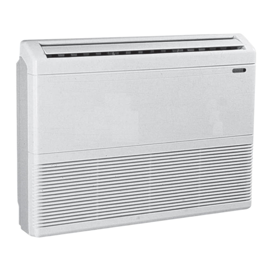
KONSOLEN ODER-DECKENGERÄTE WASSERGEKÜHLT
Janvier 2008
37.4163.282.1
10 11 355 - F.GB.I.E.D - 04
1
Kapitel
Inhaltsverzeichnis

Verwandte Anleitungen für Technibel KPSW


Inhaltszusammenfassung für Technibel KPSW
- Seite 42 BEZEICHNUNG Dieses Gerät trägt das Kennzeichen und entspricht den wesentlichen Bestimmungen der EG-Richtlinien : - Niederspannungsrichtlinie 2006/95/CE - Elektromagnetische Verträglichkeit 89/336 EWG, i. d. Fassung 92/31 und 93/68 EWG. INHALTSVERZEICHNIS 1 - Allgemeines ................2 2 - Präsentation ................. 2 3 - Installation ................
-
Seite 43: Mit Dem Gerät Mitgeliefertes Zubehör
2.2 - MIT DEM GERÄT MITGELIEFERTES ZUBEHÖR Zubehör Stck. Zubehör Stck. Dübel Schraube 4 x 10 (zur Befestigung der Platinen) Schraube 4 x 30 Isoliermaterial (für Anschlüsse) (für Wandhalterung) Wandhalterung Dichtung (für Leitungsdurchlaß) Bohrschablone Seitliche Stützen Anleitungen Federscheiben 1 Aufstellungshandbuch 1 Bedienungsanleitung Schraubenbolz H M8 Schelle... -
Seite 44: Installation Auf Dem Boden
3.2 - INSTALLATION AUF DEM BODEN Eine geeignete Geräteposition auswählen. Die Einheit kann in 4 Richtungen angeschlossen werden : Rückseite Die Bohrschablone rechts, Rückseite links, Unterseite rechts, Unterseite falzen, sie bündig ausrichten und die Bohrlöcher markieren links. (Rohre, Kondensataustritt, Stützen). 5 / 10 mm Falls notwendig, Bohrung Ø... -
Seite 45: Installation An Der Decke
5 / 10 mm Falls notwendig, Bohrung Ø 80 mm vornehmen, (oder mehrere, je nach Art der Installation). Das Frontgitter entfernen; das Gitter dazu aus den seitlichen Schienen und dem mittleren Sperrclip aushaken. Ein vorgeschnittenes Loch (oder mehrere) zur Durchführung der Rohre bohren (von der Außenseite aus arbeiten). - Seite 46 5 / 10 mm Falls notwendig, Bohrung Ø 80 mm vornehmen, (oder mehrere, je nach Art der Installation). Das Frontgitter entfernen; das Gitter dazu aus den seitlichen Schienen und dem mittleren Sperrclip aushaken. Ein vorgeschnittenes Loch (oder mehrere) zur Durchführung der Rohre bohren (von der Außenseite aus arbeiten).
-
Seite 47: Anschlüsse
4 - ANSCHLÜSSE ALLGEMEINES Seitenplatine • Die Seitenplatine entfernen, um den Zugang zu den Anschlüssen zu erleichtern. 4.1 - HYDRAULISCHE ANSCHLÜSSE 4.1.1 - ALLGEMEINES • Anschlußstutzen Wasserzulauf und -ablauf 1/2’’ Außengewinde. • Bei Kühlwasserbetrieb ist der Einbau eines Regulierventils unbedingt Kondensatröhre erforderlich, da ansonsten die Gefahr von Kondensat nachdem der Anschluß... -
Seite 48: Fernbedienung (Zubehör)
4.3.4 - FERNBEDIENUNG (Zubehör) • 2 Ausführungen : - Code 70250076 mit manueller Umschaltung Kühlen/Heizen (change-over). ("RAB 30") - Code 70250051 mit automatischer Umschaltung Kühlen/Heizen (change-over). ("RCC 10") 70250076 70250051 LED Heizen Ein Lüfterschalter mit Drehzahlauswahl LED Lüfter Ein LED Kühlen Ein Temperatureinstellungsknopf Temperatursollwerteinstellung Temperatureinstellungsknopf... - Seite 49 • Ansteuerung über Zweipunktventil (230 V) . • Lüftung kontinuierlich oder gesteuert. • Betriebsartumschaltung (Sparbetrieb oder Stand-by) über externen Kontakt. • Für technische Informationen zur Funktionsweise dieser Steuerung , siehe Technische Anleitung 10 12 151. Regelung über Ventil Stromversorgung 230V / 1 / 50Hz 70250051 G N D M B2...
-
Seite 50: Zubehör
E - Besonderheiten der Steuerung "RCC" - Code 70250051 • Betriebsartumschaltung (Heizen/Kühlen) : - An Stelle des Temperaturfühlers kann ein externer, potenzialfreier Kontakt angeschlossen werden (nicht im Lieferumfang enthalten). Beim Schliessen desselben wird der Thermostat auf Kühlbetrieb umgeschaltet, bei, Öffnen auf Heizbetrieb. -
Seite 51: Wartungshinweise
Schlauchleitungen. Die Reinigung erfolgt mit Wasser mit 5% Chlorlauge. 8 - SCHALTPLÄN SYMBOLBEZEICHNUNG DER BAUTEILE KABELFARBEN M Braun G Grau Rosa C1 M1 Kondensator O Orange W Weiß Gelb F1 Steuerkreissicherung Violett M1 Ventilator KPSW 2 / 4 KPSW 3... - Seite 52 Par souci d'amélioration constante, nos produits peuvent être modifi és sans préavis. Due to our policy of continuous development, our products are liable to modifi cation without notice. Per garantire un costante miglioramento dei nostri prodotti, ci riserviamo di modifi carli senza preaviso. En el interés de mejoras constantes, nuestros productos pueden modifi...