Herunterladen Diese Seite drucken

Werbung

Verfügbare Sprachen
  • DE

Verfügbare Sprachen

  • DEUTSCH, seite 73
AXIS T99A10 Positioning Unit 24 V AC/DC
Installation Guide

Werbung

loading

Inhaltszusammenfassung für Axis T99A10

  • Seite 1 AXIS T99A10 Positioning Unit 24 V AC/DC Installation Guide...
  • Seite 3 English France: Français Deutschland: Deutsch Italia: Italiano España: Español 日本: 日本語 中文: 简体中文...
  • Seite 4: Inhaltsverzeichnis

    Installation Guide Safety information ......... . Hazard levels .
  • Seite 5 AXIS T99A10 Positioning Unit 24 V AC/DC Câbles ............
  • Seite 6 Installation Guide Specifiche ..........Slot per scheda SD .
  • Seite 7 AXIS T99A10 Positioning Unit 24 V AC/DC 関 関 関 連 連 連 情 情 情 報 報 報 ..........
  • Seite 8 Axis Communications AB. See Contact Every care has been taken in the preparation of this information 9. document. Please inform your local Axis office of any inaccuracies or omissions. Axis Communications AB cannot Electromagnetic compatibility (EMC) be held responsible for any technical or typographical errors...
  • Seite 9 Search by product, category, or phrase and the environment, the product must be disposed of in • report problems to Axis support staff by logging in to an approved and environmentally safe recycling process. your private support area For information about your nearest designated collection •...
  • Seite 11: Safety Information

    AXIS T99A10 Positioning Unit 24 V AC/DC Safety information Hazard levels DANGER Indicates a hazardous situation which, if not avoided, will result in death or serious injury. WARNING Indicates a hazardous situation which, if not avoided, could result in death or serious injury.
  • Seite 12: Safety Instructions

    • Use only spare parts provided by or recommended by Axis. • Do not attempt to repair the product yourself. Contact Axis support or your Axis reseller for service matters. • Do not point the camera lens toward the sun or other high-intensity radiation sources because this could cause damage to the camera.
  • Seite 13: Package Contents

    AXIS T99A10 Positioning Unit 24 V AC/DC Package contents • Positioning unit • Camera housing • Power connector • I/O connector • Torx® bit T20 and T30 • Printed materials Installation Guide (this document) Extra serial number label (2x) AVHS Authentication key...
  • Seite 14: Hardware Overview

    AXIS T99A10 Positioning Unit 24 V AC/DC Hardware overview For specifications of the hardware components, see Specifications on page 35. Positioning unit (tilt) Positioning unit (pan) Base unit Camera housing...
  • Seite 15 AXIS T99A10 Positioning Unit 24 V AC/DC Camera power cable Camera network cable Camera serial interface cable Input power connector I/O connector RJ45 connector SFP slot for SFP module (SFP module not included) Illuminator cables...
  • Seite 16: How To Install The Product

    AXIS T99A10 Positioning Unit 24 V AC/DC How to install the product DANGER Risk of electric shock. All cables shall be de-energized before installing the product. CAUTION The electrical connections and conduit installations shall be made by a certified electrician and in compliance with local regulations.
  • Seite 17 AXIS T99A10 Positioning Unit 24 V AC/DC 1. Remove the four base unit screws (T30). 2. Simultaneously pull and turn the base unit counterclockwise until the arrows on the base unit and the rest of the unit are aligned. 3. Remove the base unit.
  • Seite 18: Route The Cables

    AXIS T99A10 Positioning Unit 24 V AC/DC Conduit cover clip Conduit cover Screw hole (x4) 5. For conduit installations only: remove the two conduit cover clips followed by the conduit cover. 6. Attach the base unit to the mounting surface using the appropriate fasteners in the four screw holes.
  • Seite 19 AXIS T99A10 Positioning Unit 24 V AC/DC Power cable (not included) Strain relief Grounding screw Grounding braid (not included) Bottom cable hole 1. Install the optional conduit adapters (not included). 2. Connect the grounding braid to the grounding screw. 3. Insert the power cable, I/O cable and network cable through the hole in the base unit as shown in the illustration above.
  • Seite 20 AXIS T99A10 Positioning Unit 24 V AC/DC I/O cable (optional, not included) Network cable (not included) 5. Insert the I/O cable (optional) through the strain relief with a distance of 420 mm (16½ in) from the strain relief to the end of the cable.
  • Seite 21 AXIS T99A10 Positioning Unit 24 V AC/DC Power cable (not included) I/O cable (optional, not included) Network cable (not included) Cable gasket Transparent base unit cover 8. Fit cable gaskets on the cables. See Cable thickness on page 38. 9. Insert the power, I/O and network cables including the cable gaskets through the holes in the transparent base unit cover and arrange the cables as shown in the illustration above.
  • Seite 22 AXIS T99A10 Positioning Unit 24 V AC/DC I/O connector Power connector O-ring NO TICE TICE TICE Make sure the protective earth wire is about 10 mm (3/8 in) longer than the other two wires (in the power cable), so that it will not be disconnected accidentally if pulled.
  • Seite 23 AXIS T99A10 Positioning Unit 24 V AC/DC 13. Replace the positioning unit on the base unit making sure that the arrows on the two units are aligned. 14. Turn the positioning unit clockwise back to its original position and tighten the four base unit screws (torque 3.0 Nm).
  • Seite 24: Connect The Cables

    AXIS T99A10 Positioning Unit 24 V AC/DC • C: via both of the above, in which case connection via the SFP module functions as the primary network link and connection via the fixed RJ45 connector as the fail-over link. For more information on network connector locations, see Connectors on page 35.
  • Seite 25: Install The Camera

    AXIS T99A10 Positioning Unit 24 V AC/DC Input power connector I/O connector RJ45 connector SFP slot for SFP module (SFP module not included) 2. Connect the network (optical fibre and/or RJ45), I/O and power cables. For more information on different network connectivity options, see .
  • Seite 26 AXIS T99A10 Positioning Unit 24 V AC/DC Camera housing top cover Heater holder screw (T20, x2) Heater holder with heater Camera housing bottom cover Camera housing cover screws (T20, x4) 1. Remove the four camera housing cover screws (T20) and detach the top cover from the bottom cover.
  • Seite 27 AXIS T99A10 Positioning Unit 24 V AC/DC 3. Insert the network/power/serial interface cable trough the hole in the bottom cover. 4. Fit the bottom cover on the positioning unit.
  • Seite 28 AXIS T99A10 Positioning Unit 24 V AC/DC 5. Tilt the bottom cover backward to its end position and tighten the two front screws of the positioning unit (T20, torque 3.0 Nm). NO TICE TICE TICE To reach the positioning unit screws, use a screwdriver with a long enough blade (see...
  • Seite 29 AXIS T99A10 Positioning Unit 24 V AC/DC Tilt the bottom cover forward to its end position and tighten the two rear screws of the positioning unit (T20, torque 3.0 Nm).
  • Seite 30 AXIS T99A10 Positioning Unit 24 V AC/DC Camera network cable Camera power cable from bottom cover to camera (cable not included, connector included) Camera power cable from positioning unit to bottom cover (cable and connector included) Camera serial interface cable (connector not included) 7.
  • Seite 31 AXIS T99A10 Positioning Unit 24 V AC/DC Heater connector and cable Heater holder with heater Heater holder screw (T20, x2) 8. Mount the heater holder to the camera. 9. Mount the heater holder with the camera to the camera housing bottom, and tighten the two heater holder screws (T20, torque 0.5 Nm).
  • Seite 32: Install The Ptz Driver

    AXIS T99A10 Positioning Unit 24 V AC/DC Bottom cover gasket Camera housing cover screw (T20, x4) 11. Mount the top cover to the bottom cover, and alternately tighten the four cover screws a few turns at a time until all screws are tight (T20, torque 1.5 Nm). This helps ensure that the gasket in the bottom cover is compressed evenly.
  • Seite 33 AXIS T99A10 Positioning Unit 24 V AC/DC 5. Choose the Device type from the drop-down list. To decide which device type to use, see the documentation supplied with the PTZ driver.
  • Seite 34: Further Information

    • For useful online trainings and webinars, see www.axis.com/academy Optional accessories For a complete list of available accessories for this product, go to axis.com > product > Software & Accessories. Warranty information For information about Axis’ product warranty and thereto related information, go to...
  • Seite 35: Specifications

    AXIS T99A10 Positioning Unit 24 V AC/DC Specifications To find the latest version of the product’s datasheet, go to axis.com > [product] > Support & Documentation. SD card slot NO TICE TICE TICE • Risk of damage to SD card. Do not use sharp tools, metal objects or excessive force when inserting or removing the SD card.
  • Seite 36: Power Connector

    AXIS T99A10 Positioning Unit 24 V AC/DC 6-pin configurable terminal block 0 V DC (-) DC output 12 V, max 50 mA I/O configured as input I/O configured as output Power connector 4-pin terminal block for power input. 24 V AC/DC power connector...
  • Seite 37 AXIS T99A10 Positioning Unit 24 V AC/DC Position 24 V AC 24 V DC Protective earth Protective earth 24 V AC Phase + 24 V 24 V AC Neutral Not connected Not connected 240 V AC power connector NO TICE...
  • Seite 38: Cables

    Camera power cable Cable color Specification + 24 V DC Black Operating conditions This Axis product is intended for indoor and outdoor use. Temperature Humidity 10–100% RH Normal: -50 °C to 60 °C (-58 °F to 140 °F) (non-condensing) Maximum (intermittent): 65 °C (149 °F)
  • Seite 39: Power Consumption

    169 W Important When using the 22 m (72 ft) AXIS Cable 24 V DC/24–240 V AC with AXIS T99A 24 V AC/DC, a power supply capable of delivering 220 W is required to compensate for the power loss in the cable.
  • Seite 41: Informations Sur La Sécurité

    AXIS T99A10 Positioning Unit 24 V AC/DC Informations sur la sécurité Niveaux de risques DANGER Indique une situation dangereuse qui, si elle n'est pas évitée, entraînera le décès ou des blessures graves. AVERTISSEMENT Indique une situation dangereuse qui, si elle n'est pas évitée, pourrait entraîner le décès ou des blessures graves.
  • Seite 42: Consignes De Sécurité

    Risque de choc électrique. Tous les câbles doivent être mis hors tension avant l'installation ou une intervention de maintenance sur le produit. AVERTISSEMENT Le produit Axis doit être installé par un professionnel qualifié et conformément aux lois et règlementations locales en vigueur. ATTENTION Risques de blessures.
  • Seite 43: Transport

    AXIS T99A10 Positioning Unit 24 V AC/DC Transport A A A VIS • Lors du transport du produit Axis, utilisez l'emballage d'origine ou un équivalent pour éviter d'endommager le produit.
  • Seite 44: Contenu De L'emballage

    AXIS T99A10 Positioning Unit 24 V AC/DC Contenu de l’emballage • Unité de positionnement • Boîtier de caméra • Connecteur d'alimentation • Connecteur E/S • Torx® embout T20 et T30 • Documents imprimés Guide d’installation (ce document) Étiquette supplémentaire de numéro de série (x2)
  • Seite 45: Aperçu Du Matériel

    AXIS T99A10 Positioning Unit 24 V AC/DC Aperçu du matériel Pour connaître les caractéristiques des composants matériels, consultez Caractéristiques page 67. Unité de positionnement (inclinaison) Unité de positionnement (panoramique) Opercule Unité de base Boîtier de caméra...
  • Seite 46 AXIS T99A10 Positioning Unit 24 V AC/DC Câble électrique de la caméra Câble réseau de la caméra Câble interface série de la caméra Connecteur d'alimentation d'entrée Connecteur E/S Connecteur RJ45 Emplacement SFP pour module SFP (module SFP non inclus) Câbles éclairage...
  • Seite 47: Comment Installer Le Produit

    AXIS T99A10 Positioning Unit 24 V AC/DC Comment installer le produit DANGER Risque de choc électrique. Tous les câbles doivent être hors tension avant d'installer le produit. ATTENTION Les connexions électriques et les installations de conduites doivent être effectuées par un électricien certifié...
  • Seite 48: Montage De L'unité De Base

    AXIS T99A10 Positioning Unit 24 V AC/DC Montage de l'unité de base Unité de base 1. Déposer les quatre vis de l'unité (T30). 2. Tirez et tournez simultanément l'unité de base dans le sens anti-horaire jusqu'à ce que les flèches sur l'unité de base et le reste de l'unité soient alignées.
  • Seite 49 AXIS T99A10 Positioning Unit 24 V AC/DC A A A VIS Ne pas utiliser d'outils tranchants lors de la dépose du couvercle transparent de l'unité de base. 4. Déposez le couvercle transparent de l'unité de base.
  • Seite 50: Acheminement Des Câbles

    AXIS T99A10 Positioning Unit 24 V AC/DC Clip du cache de conduit Cache de conduit Trou de vis (x4) 5. Pour des installations de conduit uniquement : déposer les deux clips du cache de conduit suivis par le cache du conduit.
  • Seite 51 AXIS T99A10 Positioning Unit 24 V AC/DC Câble d’alimentation (non fourni) Réducteur de tension vis de mise à la terre Tresse de terre (non fournie) passage du câble inférieur 1. Installez les adaptateurs de conduit en option (non fournis). 2. Reliez la tresse de terre à la vis de mise à la terre.
  • Seite 52 AXIS T99A10 Positioning Unit 24 V AC/DC Câble E/S (en option, non fourni) Câble réseau (non inclus) 5. Insérez le câble E/S (en option) à travers le réducteur de tension avec une distance de 420 mm (16½ po) du réducteur de tension jusqu'à l'extrémité du câble.
  • Seite 53 AXIS T99A10 Positioning Unit 24 V AC/DC Câble d'alimentation (non inclus) Câble E/S (en option, non fourni) Câble réseau (non inclus) Joint de câble Couvercle transparent de l'unité de base 8. Placez les joints sur les câbles. Cf. Épaisseur du câble page 70.
  • Seite 54 AXIS T99A10 Positioning Unit 24 V AC/DC Connecteur E/S Connecteur d'alimentation Joint torique A A A VIS Pour éviter toute déconnexion intempestive, le câble de protection de mise à la terre doit être plus long d'environ 10 mm (3/8 po) que les deux autres fils (dans le câble d'alimentation).
  • Seite 55 AXIS T99A10 Positioning Unit 24 V AC/DC 13. Replacez l'unité de positionnement sur l'unité de base en vous assurant que les flèches sur les deux unités sont alignées. 14. Tournez l'unité de positionnement dans le sens des aiguilles d'une montre jusqu'à sa position d'origine et serrez les quatre vis de l'unité...
  • Seite 56: Branchez Les Câbles

    AXIS T99A10 Positioning Unit 24 V AC/DC • C : via les deux solutions ci-dessus, auquel cas le raccordement via le module SFP fonctionne comme la liaison réseau primaire et le raccordement via le connecteur RJ45 fixe comme la liaison de secours.
  • Seite 57: Installation De La Caméra

    3. Replacez le couvercle, puis serrez les quatre vis du couvercle (couple de serrage 3,0 Nm). 4. Mettez le produit sous tension. Installation de la caméra A A A VIS Ce produit Axis est compatible avec plusieurs caméras réseau. Pour obtenir une liste complète des caméras prises en charge, consultez www.axis.com.
  • Seite 58 AXIS T99A10 Positioning Unit 24 V AC/DC Couvercle supérieur du boîtier de caméra Vis de fixation du chauffage (T20, x2) Support du régulateur avec régulateur de chaleur Couvercle inférieur du boîtier de caméra Vis de couvercle du boîtier de caméra (T20, x4) 1.
  • Seite 59 AXIS T99A10 Positioning Unit 24 V AC/DC 3. Insérez le câble d'interface réseau/alimentation/série à travers le trou du couvercle inférieur. 4. Montez le couvercle inférieur sur l'unité de positionnement.
  • Seite 60 AXIS T99A10 Positioning Unit 24 V AC/DC 5. Inclinez le couvercle inférieur vers l'arrière jusqu'à sa position finale et serrez les deux vis avant de l'unité de positionnement (T20, couple 3 Nm). A A A VIS Pour atteindre les vis de l'unité de positionnement, utilisez un tournevis avec une tige...
  • Seite 61 AXIS T99A10 Positioning Unit 24 V AC/DC Inclinez le couvercle inférieur vers sa position finale et serrez les deux vis arrière de l'unité de positionnement (T20, couple 3 Nm).
  • Seite 62 AXIS T99A10 Positioning Unit 24 V AC/DC Câble de réseau de caméra Câble d'alimentation de caméra du couvercle inférieur à la caméra (câble non inclus, connecteur inclus) Câble d'alimentation de l'unité de positionnement au couvercle inférieur (câble et connecteur fournis) Câble interface série de la caméra (connecteur non fourni)
  • Seite 63 AXIS T99A10 Positioning Unit 24 V AC/DC Connecteur et câble du régulateur de chaleur Support du régulateur avec régulateur de chaleur Vis du support du régulateur de chaleur (T20, x2) 8. Montez le support du régulateur de chaleur à la caméra.
  • Seite 64: Installation Du Pilote Ptz

    AXIS T99A10 Positioning Unit 24 V AC/DC Joint du couvercle inférieur Vis du couvercle du boîtier de la caméra (T20, x4) 11. Montez le couvercle supérieur au couvercle inférieur, puis serrez en alternance les quatre vis du couvercle de quelques tours à la fois jusqu’à ce que toutes les vis soient bien serrées (T20, couple de serrage 1,5 Nm).
  • Seite 65 AXIS T99A10 Positioning Unit 24 V AC/DC 3. Sélectionnez le pilote téléchargé à partir du menu déroulant Select driver to use (Sélectionner le pilote à utiliser). 4. Pour activer la fonction PTZ, sélectionnez Activate PTZ (Activer PTZ). 5. Choisissez le Device type (Type d'appareil) dans la liste déroulante. Pour déterminer le...
  • Seite 66: Informations Complémentaires

    Pour en savoir plus sur les formations, les webinaires, les tutoriels et les guides, visitez le site www.axis.com/academy. Accessoires en option Pour une liste complète des accessoires disponibles pour ce produit, accédez à axis.com> produit> Logiciel et accessoires. Informations sur la garantie Pour plus d'informations sur la garantie du produit Axis et les informations connexes, rendez-vous sur axis.com/warranty...
  • Seite 67: Caractéristiques

    AXIS T99A10 Positioning Unit 24 V AC/DC Caractéristiques Pour obtenir la dernière version de la fiche technique du produit, rendez-vous sur axis.com> produit > Assistance et documentation. Emplacement pour carte SD A A A VIS • La carte SD risque d'être endommagée. Ne pas utiliser d'outils tranchants ou d'objets métalliques et ne pas forcer lors de l'insertion ou du retrait de la carte SD.
  • Seite 68 AXIS T99A10 Positioning Unit 24 V AC/DC Un capteur de lumière numérique - Pour recevoir une valeur de l'intensité lumineuse d'un capteur de lumière externe. Cette valeur est utilisée pour contrôler la fonction jour/nuit. Bloc terminal configurable à 6 broches...
  • Seite 69: Connecteur D'alimentation

    AXIS T99A10 Positioning Unit 24 V AC/DC 0 V CC (-) Sortie CC 12 V, maxi. 50 mA Entrée/sortie configurée comme entrée Entrée/sortie configurée comme sortie Connecteur d'alimentation Bloc terminal à 4 broches pour l'alimentation. Connecteur d'alimentation 24 V CA/CC A A A VIS Cette section concerne les produits alimentés en 24 V CA et 24 V CC uniquement.
  • Seite 70: Câbles

    AXIS T99A10 Positioning Unit 24 V AC/DC Position 24 V CA 24 V CC Terre de protection Terre de protection Phase 24 V CA + 24 V 24 V CA Neutre Non connecté Non connecté Connecteur d'alimentation 240 V CA) A A A VIS Cette section concerne les produits alimentés en 100–240 V CA uniquement.
  • Seite 71: Conditions De Fonctionnement

    Rouge + 24 V CC noir Conditions de fonctionnement Ce produit Axis est destiné à être utilisé à l'intérieur et à l'extérieur. Température Humidité 10 à 100 % HR Normale : -50 °C à 60 °C (-58 °F à 140 °F) (sans condensation) Maximale (intermittente) : 65 °C (149 °F)
  • Seite 72 AXIS T99A10 Positioning Unit 24 V AC/DC Important Lorsque vous utilisez le câble AXIS de 22 m (72 ft) 24 V CC/24 à 240 V CA avec AXIS T99A 24 V CA/CC, il faut une alimentation capable de livrer 220 W pour compenser la perte de puissance dans le câble.
  • Seite 73: Sicherheitsinformationen

    AXIS T99A10 Positioning Unit 24 V AC/DC Sicherheitsinformationen Gefährdungsstufen GEFAHR Weist auf eine gefährliche Situation hin, welche, falls nicht verhindert, zu Tod oder schweren Verletzungen führen kann. WARNUNG Weist auf eine gefährliche Situation hin, welche, falls nicht verhindert, zu Tod oder schweren Verletzungen führen kann.
  • Seite 74: Sicherheitsanweisungen

    • Lagern Sie das Axis Produkt in einer trockenen und belüfteten Umgebung. • Achten Sie darauf, dass das Axis Produkt weder Stößen noch starkem Druck ausgesetzt ist. • Installieren Sie das Produkt nicht an instabilen Masten, Halterungen, Oberflächen oder Wänden.
  • Seite 75: Transport

    AXIS T99A10 Positioning Unit 24 V AC/DC Transport HINWEIS HINWEIS HINWEIS • Bei Bedarf transportieren Sie das Axis Produkt in der Originalverpackung oder einer entsprechenden Verpackung, so dass Schäden vermieden werden.
  • Seite 76: Lieferumfang

    AXIS T99A10 Positioning Unit 24 V AC/DC Lieferumfang • Positionierungseinheit • Kameragehäuse • Netzanschluss • E/A-Anschluss • Torx® Bits T20 und T30 • Gedruckte Dokumente Installationsanleitung (dieses Dokument) Zusätzliche Etiketten mit der Seriennummer (2 x) AVHS-Authentifizierungsschlüssel...
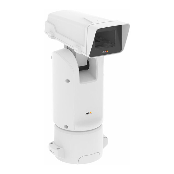
  • Seite 77: Übersicht Über Die Hardware

    AXIS T99A10 Positioning Unit 24 V AC/DC Übersicht über die Hardware Die technischen Daten für Hardwarekomponenten finden Sie unter Technische Daten auf Seite 99. Positionierungseinheit (Neigen) Positionierungseinheit (Schwenken) Deckel Basisgerät Kameragehäuse...
  • Seite 78 AXIS T99A10 Positioning Unit 24 V AC/DC Stromversorgungskabel der Kamera Netzwerkkabel der Kamera Serielles Schnittstellenkabel der Kamera Stromversorgungsanschluss Eingang E/A-Anschluss Anschluss RJ-45 SFP-Einschub für SFP-Glasfasermodule (SFP-Modul nicht enthalten) Strahlerkabel...
  • Seite 79: Installieren Des Produkts

    AXIS T99A10 Positioning Unit 24 V AC/DC Installieren des Produkts GEFAHR Stromschlaggefahr Vor der Installation oder Wartung des Produkts müssen alle Kabel von der Stromversorgung abgeklemmt werden. VORSICHT Die Installation der elektrischen Anschlüsse und Kabelkanäle darf nur von einem zugelassenen Elektriker in Übereinstimmung mit den geltenden Bestimmungen vorgenommen werden.
  • Seite 80: Montieren Der Gerätebasis

    AXIS T99A10 Positioning Unit 24 V AC/DC Montieren der Gerätebasis Gerätebasis 1. Die vier Schrauben (T30) der Gerätebasis entfernen. 2. Die Gerätebasis gleichzeitig ziehen und gegen den Uhrzeigersinn drehen, bis die Pfeile auf der Gerätebasis und dem Rest des Geräts in einer Linie stehen.
  • Seite 81 AXIS T99A10 Positioning Unit 24 V AC/DC HINWEIS HINWEIS HINWEIS Beim Entfernen der transparenten Abdeckung der Gerätebasis keine spitzen Werkzeuge verwenden. 4. Die transparente Abdeckung der Gerätebasis entfernen.
  • Seite 82: Die Kabel Verlegen

    AXIS T99A10 Positioning Unit 24 V AC/DC Klammer der Kabelführung Abdeckung der Kabelführung Schraubenbohrung (4 x) 5. Nur bei Installationen über die Kabelführung: Zuerst die beiden Klammern der Kabelführung und anschließend die Abdeckung der Kabelführung entfernen. 6. Die Gerätebasis mit geeigneten Befestigungselementen für die vier Schraubenbohrungen an der Befestigungsfläche anbringen.
  • Seite 83 AXIS T99A10 Positioning Unit 24 V AC/DC Stromversorgungskabel (nicht im Lieferumfang enthalten) Zugentlastung Masseschraube Erdungsband (nicht im Lieferumfang enthalten) Kabelöffnung unten 1. Die optionalen Kabelführungsadapter installieren (nicht im Lieferumfang enthalten). 2. Das Erdungskabel mit der Erdungsschraube befestigen. 3. Die Kabel für Stromversorgung, Netzwerk und E/A einschließlich der Kabelverschraubungen wie in der Abbildung oben durch die Öffnung des Basisgeräts...
  • Seite 84 AXIS T99A10 Positioning Unit 24 V AC/DC E/A-Kabel (optional, nicht im Lieferumfang enthalten) Netzwerkkabel (nicht im Lieferumfang enthalten) 5. Das (optionale) E/A-Kabel mit einem Abstand von 420 mm zwischen Zugentlastung und Kabelende durch die Zugentlastung führen. 6. Das Netzwerkkabel (Glasfaser oder Kabeltyp RJ-45) durch die Zugentlastung führen.
  • Seite 85 AXIS T99A10 Positioning Unit 24 V AC/DC Stromversorgungskabel (nicht im Lieferumfang enthalten) E/A-Kabel (optional, nicht im Lieferumfang enthalten) Netzwerkkabel (nicht im Lieferumfang enthalten) Kabeldichtung Transparente Abdeckung der Gerätebasis 8. Die Kabeldichtungen auf die Kabel schieben. Siehe Kabelstärke auf Seite 102.
  • Seite 86 AXIS T99A10 Positioning Unit 24 V AC/DC E/A-Anschluss Netzanschluss O-Ring HINWEIS HINWEIS HINWEIS Sicherstellen, dass die Erdungsleitung etwa 10 mm länger ist als die beiden anderen Leitungen (im Stromversorgungskabel), sodass diese bei Zugbelastung nicht unbeabsichtigt getrennt wird. Beachten Für einen leichteren Einbau empfehlen wir, etwa 90 mm des Mantels des Stromversorgungskabel und etwa 70 mm des Mantels des E/A-Kabels zu entfernen.
  • Seite 87 AXIS T99A10 Positioning Unit 24 V AC/DC 13. Das Positionierungsgerät wieder an der Gerätebasis anbringen und dabei sicherstellen, dass die Pfeile der beiden Geräte in einer Linie stehen. 14. Die Positionierungseinheit im Uhrzeigersinn in ihre Ausgangsstellung drehen und die vier Schrauben der Grundeinheit anziehen (Drehmoment 3,0 Nm).
  • Seite 88: Anschließen Der Kabel

    AXIS T99A10 Positioning Unit 24 V AC/DC • C: Mithilfe beider oben angeführten Möglichkeiten. In diesem Fall agiert der Anschluss über das SFP-Modul als die primäre Netzwerkverbindung und die Verbindung über den festen Anschluss des Typs RJ-45 als Fail-Over-Anschluss. Weitere Informationen zur Lage der Netzwerksteckverbindungen, siehe Anschlüsse auf Seite 99.
  • Seite 89: Installieren Der Kamera

    AXIS T99A10 Positioning Unit 24 V AC/DC Stromversorgungsanschluss Eingang E/A-Anschluss RJ-45-Anschluss SFP-Einschub für SFP-Module (SFP-Modul nicht enthalten) 2. Das Netzwerk (Glasfaser und/oder RJ-45), E/A und die Stromversorgung anschließen Weitere Informationen zu verschiedenen Anschlussoptionen an das Netzwerk, siehe . 3. Den Deckel austauschen und die vier Deckelschrauben anziehen (Drehmoment 3,0 Nm).
  • Seite 90 AXIS T99A10 Positioning Unit 24 V AC/DC Obere Abdeckung des Kameragehäuses Schrauben (T20, 2 St.) für Heizungshalter Heizungshalter mit Heizung Untere Abdeckung des Kameragehäuses Schrauben (T20, 4 St.), Abdeckung des Kameragehäuses 1. Die vier Schrauben (T20) des Kameragehäuses entfernen und die obere Abdeckung von der unteren Abdeckung trennen.
  • Seite 91 AXIS T99A10 Positioning Unit 24 V AC/DC 3. Das Kabel für Netzwerk / Stromversorgung / serielle Schnittstelle durch die Öffnung in der unteren Abdeckung führen. 4. Die untere Abdeckung an der Positionierungseinheit anbringen.
  • Seite 92 AXIS T99A10 Positioning Unit 24 V AC/DC 5. Die untere Abdeckung nach hinten in Endlage neigen und die beiden vorderen Schrauben (T20) der Positionierungseinheit anziehen (Drehmoment 3,0 Nm). HINWEIS HINWEIS HINWEIS Um die Schrauben der Positionierungseinheit erreichen zu können, einen Schraubendreher...
  • Seite 93 AXIS T99A10 Positioning Unit 24 V AC/DC Die untere Abdeckung nach vorn in Endlage neigen und die beiden hinteren Schrauben (T20) der Positionierungseinheit anziehen (Drehmoment 3,0 Nm).
  • Seite 94 AXIS T99A10 Positioning Unit 24 V AC/DC Netzwerkkabel der Kamera Stromversorgungskabel der Kamera von unterer Abdeckung an Kamera (Kabel nicht im Lieferumfang enthalten, Anschluss enthalten) Stromversorgungskabel der Kamera von Positionierungseinheit an untere Abdeckung (Kabel nicht im Lieferumfang enthalten, Anschluss enthalten)
  • Seite 95 AXIS T99A10 Positioning Unit 24 V AC/DC Heizungsanschluss und Kabel Heizungshalter mit Heizung Schrauben (T20, 2 x) für Heizungshalter 8. Den Heizungshalter an der Kamera anbringen. 9. Den Heizungshalter und die Kamera an der unteren Gehäuseabdeckung ausrichten und die beiden Schrauben (T20) des Heizungshalters anziehen (Drehmoment 0,5 Nm).
  • Seite 96: Installieren Des Ptz-Treibers

    AXIS T99A10 Positioning Unit 24 V AC/DC Dichtung der unteren Abdeckung Schrauben (T20, 4 x), Abdeckung des Kameragehäuses 11. Die obere Abdeckung an der unteren Abdeckung anbringen und die vier Eckschrauben (T20) in mehreren Durchgängen versetzt jeweils einige Umdrehungen eindrehen bis alle Schrauben fest angezogen sind (Drehmoment 1,5 Nm).
  • Seite 97 AXIS T99A10 Positioning Unit 24 V AC/DC 3. Den hochgeladenen Treiber aus dem Aufklappmenü Treiber auswählen wählen. 4. PTZ aktivieren wählen, um PTZ zu aktivieren. 5. Aus dem Aufklappmenü den Gerätetyp) wählen. Zur Wahl des richtigen Treibers, siehe die mit dem PTZ-Treiber gelieferte Dokumentation.
  • Seite 98: Weitere Informationen

    Unter www.axis.com/support finden Sie Firmware-Aktualisierungen für Ihre Produkte. • Nützliche Onlineschulungen und Webinare finden Sie unter www.axis.com/academy. Optionales Zubehör Eine vollständige Zubehörliste für dieses Produkt finden Sie auf axis.com > Produkt > Software und Zubehör. Gewährleistungsinformationen Informationen zur Gewährleistung für Axis-Produkte und andere in diesem Zusammenhang...
  • Seite 99: Technische Daten

    AXIS T99A10 Positioning Unit 24 V AC/DC Technische Daten Die aktuelle Version der technischen Daten des Produkts finden Sie auf axis.com unter Produkt > Support und Dokumentation. SD-Karteneinschub HINWEIS HINWEIS HINWEIS • Gefahr von Schäden an der SD-Karte. Verwenden Sie beim Einlegen oder Entfernen der SD-Karte keine scharfen/spitzen Werkzeuge oder Gegenstände aus Metall und wenden Sie...
  • Seite 100: Netzanschluss

    AXIS T99A10 Positioning Unit 24 V AC/DC Digitaler Lichtsensor - Für den Empfang eines Werts für die Umgebungslichtstärke von einem externen Lichtsensor. Dient zur Steuerung der Tag- und Nachtfunktionalität des Produkts. 6-poliger konfigurierbarer Anschlussblock 0 V Gleichstrom (-) Gleichstromausgang 12 V, max. 50 mA...
  • Seite 101 AXIS T99A10 Positioning Unit 24 V AC/DC Position 24 V Wechselstrom 24 V Gleichstrom Schutzerde Schutzerde Phase 24 V Wechselstrom + 24 V Nullleiter 24 V Wechselstrom Nicht verbunden Nicht verbunden Netzanschluss 240 V Wechselstrom HINWEIS HINWEIS HINWEIS Dieser Abschnitt bezieht sich nur auf Produkte mit Stromversorgung 100 V bis 240 V Wechselstrom.
  • Seite 102: Kabel

    Stromversorgungskabel der Kamera Kabelfarbmarkierung Technische Kenndaten + 24 V Gleichstrom Schwarz Betriebsbedingungen Dieses Axis-Produkt ist für die Verwendung im Innen- und Außenbereich ausgelegt. Temperatur Luftfeuchtigkeit Normal: -50 °C bis +60 °C Relative Luftfeuchtigkeit 10 bis 100 % (nicht kondensierend) Maximal (kurzzeitig) 65 °C...
  • Seite 103: Leistungsaufnahme

    Max. Stromverbrauch 10 W 169 W Wichtig Wenn die AXIS T99A 24 V Wechselstrom/Gleichstrom mit dem Axis-Kabel 24 V Gleichstrom/24–240 V Wechselstrom mit 22 m Länge verwendet wird, muss das Stromversorgungskabel 220 W liefern können, um Leitungsverluste auszugleichen. HINWEIS HINWEIS...
  • Seite 105: Informazioni Di Sicurezza

    AXIS T99A10 Positioning Unit 24 V AC/DC Informazioni di sicurezza Livelli di pericolo PERICOLO Indica una situazione pericolosa che, se non evitata, provoca morte o lesioni gravi. AVVERTENZA Indica una situazione pericolosa che, se non evitata, potrebbe provocare la morte o lesioni gravi.
  • Seite 106: Informazioni Di Sicurezza

    VVISO VVISO • Il dispositivo Axis deve essere utilizzato in conformità alle leggi e alle disposizioni locali. • Conservare il dispositivo Axis in un ambiente asciutto e ventilato. • Evitare di esporre il dispositivo Axis a urti o pressioni eccessive.
  • Seite 107: Contenuto Della Confezione

    AXIS T99A10 Positioning Unit 24 V AC/DC Contenuto della confezione • Unità di posizionamento • Alloggiamento per telecamera • Connettore di alimentazione • Connettore I/O • Punta Torx® T20 e T30 • Documentazione Guida all'installazione (questo documento) Etichetta aggiuntiva con numero di serie (2x)
  • Seite 108: Panoramica Dell'hardware

    AXIS T99A10 Positioning Unit 24 V AC/DC Panoramica dell'hardware Per le specifiche dei componenti hardware, vedere Specifiche alla pagina 130. Unità di posizionamento (inclinazione) Unità di posizionamento (panoramica) Coperchio Unità base Alloggiamento per telecamera...
  • Seite 109 AXIS T99A10 Positioning Unit 24 V AC/DC Cavo di alimentazione della telecamera Cavo di rete della telecamera Cavo dell'interfaccia seriale della telecamera Connettore ingresso alimentazione Connettore I/O Connettore RJ45 Slot SFP per modulo SFP (modulo SFP non incluso) Cavi dell'illuminatore...
  • Seite 110: Come Installare Il Dispositivo

    AXIS T99A10 Positioning Unit 24 V AC/DC Come installare il dispositivo PERICOLO Rischio di scosse elettriche. Tutti i cavi non saranno sotto tensione prima di installare il dispositivo. ATTENZIONE Le connessioni elettriche e l'installazione dei tubi protettivi devono essere effettuate da un elettricista certificato e in conformità...
  • Seite 111: Montaggio Dell'unità Base

    AXIS T99A10 Positioning Unit 24 V AC/DC Montaggio dell'unità base Unità base 1. Rimuovere le quattro viti (T30) dell'unità base. 2. Estrarre e ruotare simultaneamente l'unità base in senso antiorario finché le frecce sull'unità base e sul resto dell'unità non sono allineate.
  • Seite 112 AXIS T99A10 Positioning Unit 24 V AC/DC A A A VVISO VVISO VVISO Non utilizzare strumenti appuntiti durante la rimozione del coperchio trasparente dell'unità base. 4. Rimuovere il coperchio trasparente dell'unità base.
  • Seite 113: Installazione Dei Cavi

    AXIS T99A10 Positioning Unit 24 V AC/DC Clip del coperchio del tubo protettivo Coperchio del tubo protettivo Foro per vite (x4) 5. Solo per le installazioni di tubi protettivi: rimuovere le due clip del coperchio del tubo protettivo dal coperchio del tubo.
  • Seite 114 AXIS T99A10 Positioning Unit 24 V AC/DC Cavo di alimentazione (non incluso) Dispositivo antistrappo Vite di messa a terra Treccia di messa a terra (non inclusa) Foro per cavo inferiore 1. Installare gli adattatori dei tubi protettivi opzionali (non inclusi).
  • Seite 115 AXIS T99A10 Positioning Unit 24 V AC/DC Cavo I/O (opzionale, non incluso) Cavo di rete (non incluso) 5. Inserire il cavo I/O (opzionale) nel dispositivo antistrappo con una distanza di 420 mm dal dispositivo antistrappo all'estremità del cavo. 6. Inserire il cavo di rete (cavo in fibra ottica e/o cavo RJ45) nel dispositivo antistrappo ad una distanza di 580 mm dal dispositivo antistrappo all'estremità...
  • Seite 116 AXIS T99A10 Positioning Unit 24 V AC/DC Cavo di alimentazione (non incluso) Cavo I/O (opzionale, non incluso) Cavo di rete (non incluso) Guarnizione per cavi Coperchio trasparente dell'unità base 8. Inserire le guarnizioni sui cavi. Vedere Spessore del cavo alla pagina 133.
  • Seite 117 AXIS T99A10 Positioning Unit 24 V AC/DC Connettore I/O Connettore di alimentazione Anello di tenuta A A A VVISO VVISO VVISO Accertarsi che il cavo di messa a terra di protezione sia circa 10 mm più lungo degli altri due cavi (nel cavo di alimentazione) per evitare lo scollegamento accidentale.
  • Seite 118 AXIS T99A10 Positioning Unit 24 V AC/DC 13. Riposizionare l'unità di posizionamento sull'unità base accertandosi che le frecce sulle due unità siano allineate. 14. Ruotare l'unità di posizionamento in senso orario facendola tornare alla posizione originale e serrare le quattro viti dell'unità base (serraggio 3,0 Nm).
  • Seite 119: Collegamento Dei Cavi

    AXIS T99A10 Positioning Unit 24 V AC/DC • C: tramite entrambe le opzioni precedenti. In tal caso la connessione tramite le funzioni del modulo SFP è il primo collegamento di rete e la connessione tramite connettore RJ45 è il collegamento di failover.
  • Seite 120: Installazione Della Telecamera

    AXIS T99A10 Positioning Unit 24 V AC/DC Connettore ingresso alimentazione Connettore I/O Connettore RJ45 Slot SFP per modulo SFP (modulo SFP non incluso) 2. Collegare la rete (fibra ottica e/o RJ45), I/O e i cavi di alimentazione. Per ulteriori informazioni sulle differenti opzioni di connettività di rete, vedere .
  • Seite 121 AXIS T99A10 Positioning Unit 24 V AC/DC Coperchio superiore dell'alloggiamento per telecamera Vite del supporto del riscaldatore (T20, x2) Supporto del riscaldatore con riscaldatore Coperchio inferiore dell'alloggiamento per telecamera Viti del coperchio dell'alloggiamento per telecamera (T20, x4) 1. Rimuovere le quattro viti del coperchio dell'alloggiamento per telecamera (T20) e rimuovere il coperchio superiore da quello inferiore.
  • Seite 122 AXIS T99A10 Positioning Unit 24 V AC/DC 3. Inserire il cavo di rete/di alimentazione/dell'interfaccia seriale attraverso il foro nel coperchio inferiore. 4. Inserire il coperchio inferiore nell'unità di posizionamento.
  • Seite 123 AXIS T99A10 Positioning Unit 24 V AC/DC 5. Inclinare il coperchio inferiore all'indietro nella posizione finale e serrare le due viti anteriori sull'unità di posizionamento (T20, serraggio 3,0 Nm). A A A VVISO VVISO VVISO Per raggiungere le viti dell'unità di posizionamento, utilizzare un cacciavite con una lama...
  • Seite 124 AXIS T99A10 Positioning Unit 24 V AC/DC Inclinare il coperchio inferiore in avanti nella posizione finale e serrare le due viti posteriori dell'unità di posizionamento (T20, serraggio 3,0 Nm).
  • Seite 125 AXIS T99A10 Positioning Unit 24 V AC/DC Cavo di rete della telecamera Cavo di alimentazione della telecamera dal coperchio inferiore alla telecamera (cavo non incluso, connettore incluso) Cavo di alimentazione della telecamera dall'unità di posizionamento al coperchio inferiore (cavo e connettore inclusi) Cavo dell'interfaccia seriale della telecamera (connettore non incluso) 7.
  • Seite 126 AXIS T99A10 Positioning Unit 24 V AC/DC Cavo e connettore del riscaldatore Supporto del riscaldatore con riscaldatore Vite del supporto del riscaldatore (T20, x2) 8. Montare il supporto del riscaldatore sulla telecamera. 9. Montare il supporto del riscaldatore con la telecamera alla parte inferiore dell'alloggiamento della telecamera e serrare le due viti del supporto del riscaldatore (T20, serraggio 0,5 Nm).
  • Seite 127: Installazione Del Driver Ptz

    AXIS T99A10 Positioning Unit 24 V AC/DC Guarnizione del coperchio inferiore Vite del coperchio dell'alloggiamento per telecamera (T20, x4) 11. Montare il coperchio superiore al coperchio inferiore e serrare le quattro viti del coperchio in modo alternato poco alla volta finché tutte le viti sono serrate (T20, serraggio 1,5 Nm).
  • Seite 128 AXIS T99A10 Positioning Unit 24 V AC/DC 2. Per trovare il driver desiderato (ad esempio driver.ptz), fare clic su Browse (Sfoglia), quindi fare clic su Upload (Caricamento). 3. Selezionare il driver caricato dall'elenco a discesa Select driver to use (Seleziona driver da utilizzare).
  • Seite 129: Ulteriori Informazioni

    • Per servizi di formazione utili e webinar, visita il sito www.axis.com/academy Accessori opzionali Per un elenco completo degli accessori disponibili per questo dispositivo, andare al sito axis.com > dispositivi > Software e accessori. Informazioni sulla garanzia Per informazioni sulla garanzia del dispositivo Axis e informazioni ad esso relative, consultare la...
  • Seite 130: Specifiche

    AXIS T99A10 Positioning Unit 24 V AC/DC Specifiche Per la versione più aggiornata della scheda tecnica del dispositivo, visitare il sito axis.com > dispositivo > Supporto e documentazione. Slot per scheda SD A A A VVISO VVISO VVISO • Rischio di danni alla scheda SD. Non utilizzare strumenti appuntiti o oggetti metallici e non esercitare eccessiva forza durante l'inserimento o la rimozione della scheda SD.
  • Seite 131 AXIS T99A10 Positioning Unit 24 V AC/DC Un sensore luce digitale - Per ricevere un valore dell'intensità di luce dell'ambiente da un sensore di luce esterno. Viene utilizzato per controllare le funzioni per le riprese diurne/notturne del dispositivo. Morsettiera a 6 pin configurabile...
  • Seite 132 AXIS T99A10 Positioning Unit 24 V AC/DC Posizione 24 V CA 24 V CC Messa a terra di protezione Messa a terra di protezione Fase 24 V CA + 24 V 24 V CA Neutro Non connesso Non connesso Connettore di alimentazione 240 V CA...
  • Seite 133: Cavi

    • Utilizzare guarnizioni per cavi o pressacavi corrispondenti al foro e all'area dei cavi Per informazioni sugli accessori disponibili, come ad esempio guarnizioni per cavi e pressacavi adatti per altre aree dei cavi, visitare il sito Web www.axis.com. Cavo dell'interfaccia seriale della telecamera...
  • Seite 134: Consumo Energetico

    169 W Importante Quando si utilizza il cavo AXIS da 22 m 24 V CC/24 – 240 V CA con AXIS T99A 24 V AC/DC è necessario utilizzare un alimentatore in grado di fornire 220 W a compensazione della perdita di alimentazione del cavo.
  • Seite 135: Información De Seguridad

    AXIS T99A10 Positioning Unit 24 V AC/DC Información de seguridad Niveles de peligro PELIGRO Indica una situación peligrosa que, si no se evita, provocará lesiones graves o la muerte. ADVERTENCIA Indica una situación peligrosa que, si no se evita, puede provocar lesiones graves o la muerte.
  • Seite 136: Instrucciones De Seguridad

    VISO VISO • Este producto de Axis debe utilizarse de acuerdo con las leyes y normativas locales. • Almacene el producto de Axis en un entorno seco y ventilado. • Evite la exposición del producto de Axis a choques o a una fuerte presión.
  • Seite 137: Transporte

    AXIS T99A10 Positioning Unit 24 V AC/DC Transporte A A A VISO VISO VISO • Cuando transporte el producto de Axis, utilice el embalaje original o un equivalente para evitar daños en el producto.
  • Seite 138: Contenido Del Paquete

    AXIS T99A10 Positioning Unit 24 V AC/DC Contenido del paquete • Unidad de posicionamiento • Carcasa de cámara • Conector de alimentación • Conector de E/S • Torx® punta T20 y T30 • Materiales impresos Guía de instalación (este documento) Etiqueta adicional con el número de serie (2)
  • Seite 139: Información General Del Hardware

    AXIS T99A10 Positioning Unit 24 V AC/DC Información general del hardware Para conocer las especificaciones de los componentes del hardware, vea Especificaciones en la página 160. Unidad de posicionamiento (movimiento horizontal/vertical) Unidad de posicionamiento (movimiento horizontal) Tapa Unidad base Carcasa de cámara...
  • Seite 140 AXIS T99A10 Positioning Unit 24 V AC/DC Cable de alimentación de la cámara Cable de red a la cámara Cable de interfaz serie de la cámara Conector de entrada de corriente Conector de E/S Conector RJ45 Ranura SFP para módulo SFP (módulo SFP no incluido)
  • Seite 141: Cómo Instalar El Producto

    AXIS T99A10 Positioning Unit 24 V AC/DC Cómo instalar el producto PELIGRO Riesgo de descarga eléctrica. Todos los cables deben estar sin energía antes de instalar el producto. ATENCIÓN Las conexiones eléctricas y las instalaciones de los conductos debe realizarlas un electricista cualificado, de conformidad con la normativa local.
  • Seite 142: Montaje De La Unidad Base

    AXIS T99A10 Positioning Unit 24 V AC/DC Montaje de la unidad base Unidad base 1. Quite los cuatro tornillos (T30) de la unidad base. 2. Tire de la base a la vez que la gira en sentido contrario a las agujas del reloj hasta que estén alineadas las flechas de la unidad base con el resto de la unidad.
  • Seite 143 AXIS T99A10 Positioning Unit 24 V AC/DC A A A VISO VISO VISO No utilice herramientas afiladas al quitar la cubierta transparente de la unidad base. 4. Extraiga la cubierta transparente de la unidad base. Clip de cubierta de conducto...
  • Seite 144: Guía De Los Cables

    AXIS T99A10 Positioning Unit 24 V AC/DC Cubierta de conducto Orificio para tornillo (4) 5. Para instalaciones con conducto solo: retire los dos clips de cubierta de conducto y la cubierta de conducto a continuación. 6. Fije la unidad base a la superficie de montaje con los fijadores adecuados en los cuatro orificios para tornillos.
  • Seite 145 AXIS T99A10 Positioning Unit 24 V AC/DC Cable trenzado de tierra (no incluido) Orificio inferior para cable 1. Instale los adaptadores de conducto opcionales (no incluidos). 2. Conecte el cable trenzado de tierra al tornillo de tierra. 3. Pase el cable de alimentación, el cable de E/S y el cable de red a través del orificio de la unidad base como se muestra en la ilustración anterior.
  • Seite 146 AXIS T99A10 Positioning Unit 24 V AC/DC Cable de alimentación (no incluido) Cable de E/S (opcional, no incluido) Cable de red (no incluido) Junta de cable Cubierta transparente de la unidad base 8. Ponga juntas en los cables. Consulte Grosor del cable en la página 163.
  • Seite 147 AXIS T99A10 Positioning Unit 24 V AC/DC Conector de E/S Conector de alimentación Junta tórica A A A VISO VISO VISO Asegúrese de que el cable de tierra protector sea unos 10 mm más largo que los otros dos cables del cable de alimentación, de forma que no se desconecte accidentalmente si se tira de él.
  • Seite 148 AXIS T99A10 Positioning Unit 24 V AC/DC 13. Vuelva a poner la unidad de posicionamiento en la unidad base, comprobando que las flechas de ambas unidades están alineadas. 14. Gire la unidad de posicionamiento en sentido horario hasta su posición original y apriete los cuatro tornillos de la base (par 3,0 Nm).
  • Seite 149: Conexión De Los Cables

    AXIS T99A10 Positioning Unit 24 V AC/DC • C: mediante las dos opciones anteriores, en cuyo caso la conexión a través del módulo SFP funciona como enlace de red principal y la conexión a través del conector RJ45 fijado es el enlace para casos de error.
  • Seite 150: Instalación De La Cámara

    AXIS T99A10 Positioning Unit 24 V AC/DC Conector de entrada de corriente Conector de E/S Conector RJ45 Ranura SFP para módulo SFP (módulo SFP no incluido) 2. Conecte la red (fibra óptica o RJ45), la E/S y los cables de alimentación. Para obtener más información sobre las opciones de conectividad de la red, consulte .
  • Seite 151 AXIS T99A10 Positioning Unit 24 V AC/DC Cubierta superior de la carcasa de la cámara Tornillos del soporte del calefactor (T20) (2) Soporte del calefactor con calefactor Cubierta inferior de la carcasa de la cámara Tornillos de la cubierta de la carcasa de la cámara (T20) (4) 1.
  • Seite 152 AXIS T99A10 Positioning Unit 24 V AC/DC 3. Pase el cable de red/alimentación/interfaz serie por el orificio de la cubierta inferior. 4. Ponga la cubierta inferior en la unidad de posicionamiento.
  • Seite 153 AXIS T99A10 Positioning Unit 24 V AC/DC 5. Incline la cubierta inferior hacia atrás al máximo y apriete los dos tornillos delanteros de la unidad de posicionamiento (T20, par 3,0 Nm). A A A VISO VISO VISO Use un destornillador de hoja larga para llegar a los tornillos de la unidad de...
  • Seite 154 AXIS T99A10 Positioning Unit 24 V AC/DC Incline la cubierta inferior hacia delante al máximo y apriete los dos tornillos traseros de la unidad de posicionamiento (T20, par 3,0 Nm).
  • Seite 155 AXIS T99A10 Positioning Unit 24 V AC/DC Cable de red de la cámara Cable de alimentación de la cubierta inferior a la cámara (cable no incluido, conector incluido) Cable de alimentación de la unidad de posición a la cubierta inferior (cable y conector incluidos) Cable de interfaz serie a la cámara (conector no incluido)
  • Seite 156 AXIS T99A10 Positioning Unit 24 V AC/DC Conector y cable del calefactor Soporte del calefactor con calefactor Tornillos del soporte del calefactor (T20, 2) 8. Fije el soporte del calefactor a la cámara. 9. Fije el soporte del calefactor con la cámara a la parte inferior de la carcasa de la cámara y apriete los dos tornillos del soporte del calefactor (T20, par 0,5 Nm).
  • Seite 157: Instalación Del Controlador Ptz

    AXIS T99A10 Positioning Unit 24 V AC/DC Junta de la cubierta inferior Tornillos de la cubierta de la carcasa (T20, 4) 11. Una las cubiertas superior e inferior y vaya apretando poco a poco, alternativamente, los cuatro tornillos de la cubierta, hasta que todos estén apretados (T20, par 1,5 Nm).
  • Seite 158 AXIS T99A10 Positioning Unit 24 V AC/DC 3. Seleccione el controlador cargado en la lista desplegable Select driver to use (Seleccionar controlador para usar). 4. Seleccione Activate PTZ (Activar PTZ) para habilitar PTZ. 5. Seleccione el Device type (Tipo de dispositivo) en la lista desplegable. Para decidir el tipo de dispositivo que va a utilizar, consulte la documentación suministrada con...
  • Seite 159: Más Información

    Para webinars y cursos online que pueden resultarle útiles, vaya a www.axis.com/academy Accesorios opcionales Para conocer una lista completa de los accesorios disponibles para este producto, vaya a axis.com > product (producto) > Software & Accessories (Software y accesorios). Información de garantía Para obtener más detalles sobre la garantía del producto Axis y la información relacionada con...
  • Seite 160: Especificaciones

    AXIS T99A10 Positioning Unit 24 V AC/DC Especificaciones Para acceder a la versión más reciente de la hoja de datos del producto, visite axis.com > Productos> Soporte técnico y documentación. Ranura para tarjetas SD A A A VISO VISO VISO •...
  • Seite 161 AXIS T99A10 Positioning Unit 24 V AC/DC Sensor de luz digital - Recibir un valor de la intensidad de la luz ambiental desde un sensor de luz externo. Se utiliza para controlar la funcionalidad día/noche del producto. Bloque de terminales configurable de 6 pines 0 V CC (-) Salida de CC 12 V, 50 mA máx.
  • Seite 162 AXIS T99A10 Positioning Unit 24 V AC/DC Posición 24 V CA 24 V CC Conexión a tierra de protección Conexión a tierra de protección Fase de 24 V CA + 24 V Neutro de 24 V CA No conectado No conectado Conector de alimentación de 240 V CA...
  • Seite 163: Cables

    Color del cable Especificaciones Rojo + 24 V CC Negro Condiciones de funcionamiento Este producto de Axis se ha creado para su uso en interiores y exteriores. Temperatura Humedad Normal: de -50 °C a 60 °C Humedad relativa 10–100 % (sin condensación) Máxima (intermitente): 65 °C...
  • Seite 164: Consumo De Energía

    169 W Importante Si se usa el cable AXIS de 22 m de 24 V CC/24–240 V CA con AXIS T99A 24 V CA/CC, se necesitará una fuente de alimentación con capacidad de 220 W para compensar la pérdida de alimentación en el cable.
  • Seite 165: 安 安 安 全 全 全 情 情 情 報 報 報

    AXIS T99A10 Positioning Unit 24 V AC/DC 安 安 安 全 全 全 情 情 情 報 報 報 危 危 危 険 険 険 レ レ レ ベ ベ ベ ル ル ル 危険 回避しない場合、死亡または重傷につながる危険な状態を⽰します。 警告 回避しない場合、死亡または重傷につながるおそれのある危険な状態を ⽰します。 注意...
  • Seite 166: 安 安 安 全 全 全 手 手 手 順 順 順

    AXIS T99A10 Positioning Unit 24 V AC/DC 安 安 安 全 全 全 ⼿ ⼿ ⼿ 順 順 順 危険 感電の危険があります。 製品の設置やメンテナンスを⾏う前にすべての ケーブルの通電を切ってください。 警告 本製品の設置は、お使いになる地域の法律や規制に準拠して、訓練を受け た専⾨技術者が⾏ってください。 注意 損傷の危険があります。 可動部分。 動作中は、体を製品に近づけないで ください。 製品の設置やメンテナンスを⾏う前に、電源を切ってください。 注意 損傷の危険があります。 熱くなった表⾯。 動作中は、本製品に触れな いでください。 製品のメンテナンスを⾏う前に、電源を切り、表⾯が冷 えるまで待ってください。 注記...
  • Seite 167 AXIS T99A10 Positioning Unit 24 V AC/DC 輸 輸 輸 送 送 送 注記 • 本製品を運搬する際は、製品が損傷しないよう、元の梱包か同等の梱包を 使⽤してください。...
  • Seite 168: パ パ パ ッ ッ ッ ケ ケ ケ ー ー ー ジ ジ ジ の の の 内 内 内 容 容 容

    AXIS T99A10 Positioning Unit 24 V AC/DC パ パ パ ッ ッ ッ ケ ケ ケ ー ー ー ジ ジ ジ の の の 内 内 内 容 容 容 ポジショニングユニット • カメラハウジング • 電源コネクター • I/Oコネクター • Torx® ビットT20およびT30 •...
  • Seite 169: ハ ハ ハ ー ー ー ド ド ド ウ ウ ウ ェ ェ ェ ア ア ア の の の 概 概 概 要 要 要

    AXIS T99A10 Positioning Unit 24 V AC/DC ハ ハ ハ ー ー ー ド ド ド ウ ウ ウ ェ ェ ェ ア ア ア の の の 概 概 概 要 要 要 190ページの、仕様 ハードウェアコンポーネントの仕様については、 を参照し てください。 ポジショニングユニット(チルト) ポジショニングユニット(パン) 蓋...
  • Seite 170 AXIS T99A10 Positioning Unit 24 V AC/DC カメラの電源ケーブル カメラのネットワークケーブル カメラのシリアルインターフェースケーブル ⼊⼒電⼒コネクター I/Oコネクター RJ45コネクター SFPモジュール⽤SFPスロット (SFPモジュールは付属していません) イルミネーターケーブル...
  • Seite 171: 製 製 製 品 品 品 の の の 取 取 取 り り り 付 付 付 け け け 方 方 方 法 法 法

    AXIS T99A10 Positioning Unit 24 V AC/DC 製 製 製 品 品 品 の の の 取 取 取 り り り 付 付 付 け け け ⽅ ⽅ ⽅ 法 法 法 危険 感電の危険があります。 製品を設置する前に、すべてのケーブルの通電 を切ってください。 注意 電気接続およびコンジットの取り付けは、必ず資格のある電気技師が地域...
  • Seite 172 AXIS T99A10 Positioning Unit 24 V AC/DC 1. ベースユニットのネジ4本 (T30) を外します。 2. ベースユニットを引きながら反時計回りに回し、ベースユニット上の⽮印 と他のユニット上の⽮印の位置を合わせます。 3. ベースユニットを取り外します。 注記 透明ベースユニットカバーの取り外しの際には、鋭利な⼯具を使⽤しな いでください。 4. 透明ベースユニットカバーを取り外します。...
  • Seite 173: ケーブルの配線

    AXIS T99A10 Positioning Unit 24 V AC/DC コンジットカバークリップ コンジットカバー ネジ⽳ (x4) 5. コンジットの取り付けの場合にのみ、 2つのコンジットカバークリップを 取り外し、コンジットカバーを取り外します。 6. 4つのネジ⽳に適したファスナーを使⽤して、ベースユニットを取付⾯に 取り付けます。 ケ ケ ケ ー ー ー ブ ブ ブ ル ル ル の の の 配 配 配 線 線 線 警告...
  • Seite 174 AXIS T99A10 Positioning Unit 24 V AC/DC 電源ケーブル (付属していません) ストレインリリーフ アース端⼦ネジ 接地編組 (付属していません) 底部ケーブル孔 1. オプションのコンジットアダプター (付属していません) を取り付けます。 2. 接地編組をアース端⼦ネジに接続します。 3. 上図に⽰すように、ベースユニットの⽳から電源ケーブル、I/Oケーブ ル、およびネットワークケーブルを挿⼊します。 あるいは、それらを 底部ケーブル孔から挿⼊します。 4. ストレインリリーフからケーブルの先端までの距離が530 mmになるよう に、ストレインリリーフを通じて電源ケーブルを挿⼊します。...
  • Seite 175 AXIS T99A10 Positioning Unit 24 V AC/DC I/Oケーブル (オプション、付属していません) ネットワークケーブル (付属していません) 5. ストレインリリーフからケーブルの先端までの距離が420 mm になるよう に、ストレインリリーフを通じてI/Oケーブル (オプション) を挿⼊します。 6. ストレインリリーフからコネクターの先端までの距離が580 mmになるよ うに、ストレインリリーフを通じてネットワークケーブル (光ファイバー ケーブルやRJ45ケーブル) を挿⼊します。 さまざまなネットワーク接続オプ ションの詳細については、を参照してください。 7. 3つのストレインリリーフを閉じて締めます。...
  • Seite 176 AXIS T99A10 Positioning Unit 24 V AC/DC 電源ケーブル (付属していません) I/Oケーブル (オプション、付属していません) ネットワークケーブル (付属していません) ケーブルガスケット 透明ベースユニットカバー 193ページの、ケー 8. ケーブルに合ったケーブルガスケットを取り付けます。 ブルの太さ を参照してください。 9. 上図に⽰すように、ケーブルガスケットを含めて、電源ケーブル、I/Oケー ブル、ネットワークケーブルを透明ベースユニットのカバー孔から挿⼊ し、ケーブルの配置を調整します。 注記 光ファイバーとRJ45ケーブルの両⽅をネットワーク接続に使⽤している場 合、光ケーブルはI/Oケーブルと同じケーブルガスケットを通します。 漏電 防⽌のために、シーラントをケーブルとケーブルガスケットの間に貼り付 けます。 さまざまなネットワーク接続オプションの詳細については、を 参照してください。 10. ベースユニットの透明ベースユニットカバーを交換し、⽳の内側にケー ブルガスケットをはめ込みます。...
  • Seite 177 AXIS T99A10 Positioning Unit 24 V AC/DC I/Oコネクター 電源コネクター O-リング 注記 保護アース線は他の2本の線 (電源ケーブル) より10 mmほど⻑くし、引っ張ら れたときに不意に切断しないようにしてください。 注意 簡単に取り付けるために、電源ケーブルジャケットを約90 mm、およびI/O ケーブルジャケットを70 mm ほど剥ぎ取ることをお勧めします。 190ページの、コネクター を参照して電源およびI/Oコネクターを取り 付けます。 12. ネットワークケーブル、I/Oケーブル、および電源ケーブルのケーブルガス ケットからコネクターの端までの距離が、それぞれ240 mm、170 mm、 160 mmになるように調整します。 注記 O-リングが透明ベースユニットカバーに正しく取り付けられていること を確認します。...
  • Seite 178 AXIS T99A10 Positioning Unit 24 V AC/DC 13. ポジショニングユニットをベースユニットの上に戻し、2つのユニット上 の⽮印の位置が合っていることを確認します。 14. ポジショニングユニットを元の位置に戻るまで時計回りに回し、ベース ユニットのネジ4本を締めます (トルク3.0 Nm)。 注記 2つのユニットを取り付けるときに、ケーブルが締め付けられないように 注意してください。 ネットワークリンクのインストールには、次のようにさまざまなオプションがあ ります。 A: SFPポートで (それぞれのコネクターを使⽤して) SFPモジュールに接続さ • れた光ファイバーまたはRJ45ケーブルを介して接続。...
  • Seite 179: ケーブルの接続

    AXIS T99A10 Positioning Unit 24 V AC/DC B: 固定RJ45コネクターに接続されたRJ45ケーブルを介して接続。 • C: 上記の両⽅を使⽤して接続。この場合、SFPモジュール経由の接続をプラ • イマリネットワークリンクとして使⽤し、固定RJ45コネクター経由の接続 はフェイルオーバーリンクとして使⽤します。 190ページの、コネクター ネットワークコネクターの位置の詳細については、 を参 照してください。 注意 • SFPモジュールは付属していません。 利⽤可能なSFPモジュールについて www.axis.com は、 を参照してください。 • 当該SFPモジュールを使⽤する光ファイバーケーブルのみを介してネット ワークリンクを確⽴する⽅法は、ケーブルを⻑距離に設置するスタンドアロ ンのソリューションとして有効です。 ケ ケ ケ ー ー ー ブ ブ ブ ル ル ル の の の 接 接 接 続 続 続...
  • Seite 180: カメラの設置

    AXIS T99A10 Positioning Unit 24 V AC/DC ⼊⼒電⼒コネクター I/Oコネクター RJ45コネクター SFPモジュール⽤SFPスロット (SFPモジュールは付属していません) 2. ネットワーク (光ファイバーまたはRJ45) に接続し、I/Oおよび電源ケーブル を接続します。 さまざまなネットワーク接続オプションの詳細について は、を参照してください。 3. 蓋を元に戻し、4つの蓋⽌めネジを締めます (トルク3.0 Nm)。 4. 製品の電源を⼊れます。 カ カ カ メ メ メ ラ ラ ラ の の の 設 設 設 置 置 置...
  • Seite 181 AXIS T99A10 Positioning Unit 24 V AC/DC カメラハウジングの上蓋 ヒーターホルダーネジ (T20×2) ヒーターとヒーターホルダー カメラハウジングの裏蓋 カメラハウジングカバーのネジ (T20×4) 1. カメラハウジングカバーのネジ (T20) 4本を外し、裏蓋から上蓋を取り 外します。 2. ヒーターホルダーネジ (T20) 2本を外して、裏蓋からヒーターを取り外 します。...
  • Seite 182 AXIS T99A10 Positioning Unit 24 V AC/DC 3. 裏蓋の⽳にネットワーク/電源/シリアルインターフェースケーブルを 通します。 4. ポジショニングユニットに裏蓋をはめ込みます。...
  • Seite 183 AXIS T99A10 Positioning Unit 24 V AC/DC 5. 裏蓋を端まで後⽅に傾け、ポジショニングユニットの正⾯ネジ (T20、トル ク3.0 Nm) 2本を締めます。 注記 ポジショニングユニットのネジを締めるには、ブレード部が⼗分に⻑いス クリュードライバーを使⽤します (上図を参照)。...
  • Seite 184 AXIS T99A10 Positioning Unit 24 V AC/DC 裏蓋を端まで前⽅に傾け、ポジショニングユニットの背⾯ネジ (T20、トル ク3.0 Nm) 2本を締めます。...
  • Seite 185 AXIS T99A10 Positioning Unit 24 V AC/DC カメラのネットワークケーブル 裏蓋からカメラまでのカメラ電源ケーブル (ケーブルは別売、コネ クターは付属) ポジショニングユニットから裏蓋までのカメラ電源ケーブル (ケー ブルおよびコネクターは付属) カメラのシリアルインターフェースケーブル (コネクター別売) 7. カメラネットワーク、シリアルインターフェース、および電源ケーブル 193ページの、カメラ を接続します。 ケーブルの仕様の詳細については、 の電源ケーブル 193ページの、カメラのシリアルインターフェー および スケーブル を参照してください。...
  • Seite 186 AXIS T99A10 Positioning Unit 24 V AC/DC ヒーターコネクターとケーブル ヒーターとヒーターホルダー ヒーターホルダーネジ (T20×2) 8. ヒーターホルダーをカメラに取り付けます。 9. カメラとヒーターホルダーをカメラハウジングの底⾯に取り付け、ヒー ターホルダーネジ (T20、トルク0.5 Nm) 2本を締めます。 10. ヒーターケーブルを接続します。...
  • Seite 187: Ptzドライバーのインストール

    AXIS T99A10 Positioning Unit 24 V AC/DC 裏蓋ガスケット カメラハウジングカバーのネジ (T20×4) 11. 上蓋を裏蓋に取り付け、4本の蓋⽤ネジ (T20、トルク1.5 Nm) を交互に数回 ずつ回してすべてのネジが締まるまで繰り返します。 これにより、裏蓋の ガスケットに均等に⼒が掛かります。 PTZ ド ド ド ラ ラ ラ イ イ イ バ バ バ ー ー ー の の の イ イ イ ン ン ン ス ス ス ト ト ト ー ー ー ル ル ル...
  • Seite 188 AXIS T99A10 Positioning Unit 24 V AC/DC 3. [Select Select driver Select driver driver to to to use use ( ( ( 使 使 使 ⽤ ⽤ ⽤ す す す る る る ド ド ド ラ ラ ラ イ イ イ バ バ バ ー ー ー を を を 選 選 選 択 択 択 す す す る る る ) ) ) ] ドロップダウンリス...
  • Seite 189: 関 関 関 連 連 連 情 情 情 報 報 報

    AXIS T99A10 Positioning Unit 24 V AC/DC 関 関 関 連 連 連 情 情 情 報 報 報 www.axis.com 本書の最新バージョンについては、 にアクセスしてください。 • ご使⽤の製品の新しいファームウェアがリリースされていないかを確認す • www.axis.com/support るには、 にアクセスしてください。 役に⽴つオンライントレーニングおよびWebセミナーをご⽤意しており • www.axis.com/academy ます。 をご覧ください。 オ オ オ プ プ プ シ シ シ ョ ョ ョ ン ン ン ア ア ア ク ク ク セ セ セ サ サ サ リ リ リ ー ー ー...
  • Seite 190: Sdカードスロット

    AXIS T99A10 Positioning Unit 24 V AC/DC 仕 仕 仕 様 様 様 最新バージョンの製品データシートについては、Axisのホームページaxis.com > [製 品] > [サポートとドキュメント] を参照してください。 SD カ カ カ ー ー ー ド ド ド ス ス ス ロ ロ ロ ッ ッ ッ ト ト ト...
  • Seite 191 AXIS T99A10 Positioning Unit 24 V AC/DC デ デ デ ジ ジ ジ タ タ タ ル ル ル ラ ラ ラ イ イ イ ト ト ト セ セ セ ン ン ン サ サ サ ー ー ー - - - 外光センサーから周囲照明の強度の値を受信します。 こ...
  • Seite 192 AXIS T99A10 Positioning Unit 24 V AC/DC 24 V AC 位置 24 V DC 保護アース 保護アース + 24 V 24 V ACフェーズ 24 V ACニュートラル 未接続 未接続 240 V V V AC AC 電 電 電 源 源 源 コ コ コ ネ ネ ネ ク ク ク タ タ タ ー ー ー...
  • Seite 193: ケーブル

    AXIS T99A10 Positioning Unit 24 V AC/DC ケ ケ ケ ー ー ー ブ ブ ブ ル ル ル ケ ケ ケ ー ー ー ブ ブ ブ ル ル ル の の の 太 太 太 さ さ さ...
  • Seite 194: 消費電力

    最 最 最 ⼤ ⼤ ⼤ 消 消 消 費 費 費 電 電 電 ⼒ ⼒ ⼒ 10 W 169 W 重要 AXIS T99A 24 V AC/DCで22 mのAXISケーブル (24 V DC/24〜240 V AC) を使⽤ する場合、ケーブル内の電⼒損失を補償するために、220 Wの供給が可能 な電源が必要です。 注記 通常消費電⼒値は、以下の条件で算出されます。...
  • Seite 195: 安 安 安 全 全 全 信 信 信 息 息 息

    AXIS T99A10 Positioning Unit 24 V AC/DC 安 安 安 全 全 全 信 信 信 息 息 息 危 危 危 险 险 险 等 等 等 级 级 级 危险 表示如果不避免则会导致死亡或严重伤害的危险情况。 警告 表示如果不避免则可能导致死亡或严重伤害的危险情况。 小心 表示如果不避免则可能导致轻微或中度伤害的危险情况。 注意 表示如果不避免则可能导致财产损失的情况。 其 其 其 他 他 他 消 消 消 息 息 息 等 等 等 级 级 级...
  • Seite 197: 安 安 安 全 全 全 说 说 说 明 明 明

    AXIS T99A10 Positioning Unit 24 V AC/DC 安 安 安 全 全 全 说 说 说 明 明 明 危险 电击风险。 安装产品或执行产品维护之前,所有电缆都应断电。 警告 安讯士产品应由受过培训的专业人员进行安装,并遵守当地法律和法规。 小心 伤害风险。 活动部件。 操作期间,请保持身体部位远离产品。 安装或 维护产品时,请断开电源。 小心 伤害风险。 灼热的表面。 请勿在操作期间触摸该产品。 执行产品维护时, 请断开电源并让表面冷却。 注意 • 使用安讯士产品时应遵守当地法律和法规。 • 在干燥通风的环境中存放安讯士产品。...
  • Seite 198: 包 包 包 装 装 装 内 内 内 容 容 容

    AXIS T99A10 Positioning Unit 24 V AC/DC 包 包 包 装 装 装 内 内 内 容 容 容 定位单元 • 摄像机护罩 • 电源连接器 • I/O 连接器 • Torx® 位 T20 和 T30 • 印刷资料 • 安装指南(本文档) 额外的序列号标签(2 个) AVHS 身份验证密钥...
  • Seite 199: 硬 硬 硬 件 件 件 概 概 概 览 览 览

    AXIS T99A10 Positioning Unit 24 V AC/DC 硬 硬 硬 件 件 件 概 概 概 览 览 览 规格 在第219页 有关硬件组件的规格,请参见 。 定位单元(垂直转动) 定位单元(水平转动) 盖 底座单元 摄像机护罩...
  • Seite 200 AXIS T99A10 Positioning Unit 24 V AC/DC 摄像机电源线 摄像机网络电缆 摄像机串口线 输入电源连接器 I/O 连接器 RJ45 连接器 SFP 模块的 SFP 插槽(不包括 SFP 模块) 照明器电缆...
  • Seite 201: 如 如 如 何 何 何 安 安 安 装 装 装 产 产 产 品 品 品

    AXIS T99A10 Positioning Unit 24 V AC/DC 如 如 如 何 何 何 安 安 安 装 装 装 产 产 产 品 品 品 危险 电击风险。 安装产品之前,所有电缆都应断电。 小心 电气连接和导线管安装应由经过认证的电工执行,并遵守当地法规。 小心 伤害风险。 活动部件。 操作期间,请保持身体部位远离产品。 安装或 维护产品时,请断开电源。 小心 伤害风险。 灼热的表面。 请勿在操作期间触摸该产品。 执行产品维护时,...
  • Seite 202 AXIS T99A10 Positioning Unit 24 V AC/DC 2. 同时逆时针拉转底座单元,直到底座单元和该单元其余部分的箭头对齐。 3. 移除底座单元。 注意 移除透明底座单元盖板时,请勿使用尖锐工具。 4. 移除透明底座单元盖板。...
  • Seite 203 AXIS T99A10 Positioning Unit 24 V AC/DC 导线管盖夹 导线管盖 螺丝孔(4 个) 5. 仅适用于导线管安装: 取下两个导线管盖夹,然后取下导线管盖。 6. 在四个螺丝孔中使用适当的紧固件将底座单元固定到安装表面。 布 布 布 线 线 线 警告 电击风险。 本产品应同时使用电源线中的保护地线和接地编织层进行接地。 确 保保护地线和接地编织层的两端与其各自的接地表面接触。 重要 电缆厚度 在 仅使用符合指定电缆区域要求的电缆。 有关详细信息,请参见 第221页 。...
  • Seite 204 AXIS T99A10 Positioning Unit 24 V AC/DC 电源线(不包括) 应力消除器 接地螺丝 接地编织层(不包括) 底部电缆孔 1. 安装可选的导线管适配器(不包括)。 2. 将接地编织层连接到接地螺丝。 3. 将电源线、I/O 电缆和网络电缆穿过底座单元上的孔(如上图所示)。 或 者,将其穿过底部电缆孔。 4. 将电源线穿过应力消除器,并保持应力消除器与电缆末端距离为 530 毫 米(21 英寸)。...
  • Seite 205 AXIS T99A10 Positioning Unit 24 V AC/DC I/O 电缆(可选,不包括) 网络电缆(不包括) 5. 将 I/O 电缆(可选)穿过应力消除器,并保持应力消除器与电缆末端的距离 为 420 毫米(16½ 英寸)。 6. 将网络电缆(光纤电缆和/或 RJ45 电缆)穿过应力消除器,并保持应力消除 器与连接器末端的距离为 580 毫米(23 英寸)。 有关不同网络连接选项的 详细信息,请参见。 7. 合上并拧紧这三个应力消除器。...
  • Seite 206 AXIS T99A10 Positioning Unit 24 V AC/DC 电源线(不包括) I/O 电缆(可选,不包括) 网络电缆(不包括) 电缆垫片 透明底座单元盖板 电缆厚度 在第221页 8. 将电缆垫片安装到电缆上。 请参见 。 9. 将电源线、I/O 电缆和网络电缆(包括电缆垫片)穿过透明底座单元盖板上的 孔,然后按照上图所示进行布线。 注意 如果您同时使用光纤电缆和 RJ45 电缆进行网络连接,请将光纤电缆与 I/O 电缆 穿过同一电缆垫片。 在电缆和电缆垫片之间涂抹密封剂以防电缆滑出。 有关不 同网络连接选项的详细信息,请参见 。 10. 更换底座单元上的透明底座单元盖板,并将电缆垫片安装在孔内。...
  • Seite 207 AXIS T99A10 Positioning Unit 24 V AC/DC I/O 连接器 电源连接器 O 形环 注意 保护地线务必比其他两条线(在电源线中)长约 10 毫米(3/8 英寸),以 免拉扯时意外断开。 备注 我们建议您将电源线护套剥去约 90 毫米(3½ 英寸),并将 I/O 电缆护套剥去 70 毫米(2¾ 英寸),以方便安装。 接口 在第219页 11. 安装电源连接器和 I/O 连接器,请参见 。 12. 调整网络、I/O 和电源线,以使电缆垫片与连接器末端的距离分别为 240 毫米...
  • Seite 208 AXIS T99A10 Positioning Unit 24 V AC/DC 13. 调整底座单元上的定位单元,从而确保两个单元上的箭头对齐。 14. 将定位单元顺时针转回其原始位置,然后拧紧四颗底座单元螺丝(扭矩 3.0 Nm)。 注意 安装这两个单元时,确保电缆不会被夹住。 您有不同的网络链路安装选项: A: 通过光纤电缆或与 SFP 插槽中的 SFP 模块(带有相应的连接器)连接 • 的 RJ45 电缆。 B: 通过与固定式 RJ45 连接器连接的 RJ45 电缆。 • C: 同时连接上述两种电缆,在此情况下,通过 SFP 模块实现的连接用作主 • 网络链路,而通过固定式 RJ45 连接器实现的连接用作故障转移链路。...
  • Seite 209: 连接电缆

    AXIS T99A10 Positioning Unit 24 V AC/DC 接口 在第219页 有关网络连接器位置的详细信息,请参见 。 备注 www.axis.com • 不包括 SFP 模块。 有关可用 SFP 模块的详细信息,请参见 • 仅通过使用相应 SFP 模块的光纤电缆建立网络链路可用作远程布线安装的 独立解决方案。 连 连 连 接 接 接 电 电 电 缆 缆 缆 1. 松开四颗盖子螺丝 (T20),然后取下盖子。...
  • Seite 210: 安装摄像机

    AXIS T99A10 Positioning Unit 24 V AC/DC 输入电源连接器 I/O 连接器 RJ45 连接器 SFP 模块的 SFP 插槽(不包括 SFP 模块) 2. 连接网络(光纤和/或 RJ45)、I/O 和电源线。 有关不同网络连接选项的 详细信息,请参见 。 3. 更换盖子,然后拧紧四颗盖子螺丝(扭矩 3.0 Nm)。 4. 接通产品电源。 安 安 安 装 装 装 摄 摄 摄 像 像 像 机 机 机...
  • Seite 211 AXIS T99A10 Positioning Unit 24 V AC/DC 摄像机护罩顶盖 加热器固定架螺丝(T20,2 颗) 带加热器的加热器固定架 摄像机护罩底盖 摄像机护罩盖螺丝(T20,4 颗) 1. 移除四颗摄像机护罩盖螺丝 (T20),然后从底盖上拆下顶盖。 2. 移除两颗加热器固定架螺丝 (T20),然后从底盖上取下加热器。...
  • Seite 212 AXIS T99A10 Positioning Unit 24 V AC/DC 3. 将网络电缆/电源线/串口线穿过底盖上的孔。 4. 将底盖安装在定位单元上。...
  • Seite 213 AXIS T99A10 Positioning Unit 24 V AC/DC 5. 将底盖向后倾斜到其终端位置,然后拧紧定位单元前面两颗螺丝(T20, 扭矩 3.0 Nm)。 注意 要够到定位单元螺丝,请使用具有足够长刀片的螺丝刀(请见上图)。...
  • Seite 214 AXIS T99A10 Positioning Unit 24 V AC/DC 将底盖向前倾斜到其终端位置,然后拧紧定位单元后面两颗螺丝(T20, 扭矩 3.0 Nm)。...
  • Seite 215 AXIS T99A10 Positioning Unit 24 V AC/DC 摄像机网络电缆 从底盖到摄像机的摄像机电源线(不含电缆,含连接器) 从定位单元到底盖的摄像机电源线(含电缆和连接器) 摄像机串口线(不含连接器) 摄像机 7. 连接摄像机网络、串口和电源线。 有关电缆规格的详细信息,请参见 电源线 在第222页 摄像机串口线 在第222页 和 。...
  • Seite 216 AXIS T99A10 Positioning Unit 24 V AC/DC 加热器连接器和电缆 带加热器的加热器固定架 加热器固定架螺丝(T20,2 颗) 8. 将加热器固定架安装到摄像机。 9. 将加热器固定架及摄像机安装到摄像机外壳底部,然后拧紧两颗加热器固 定架螺丝(T20,扭矩 0.5 Nm)。 10. 连接加热器电缆。...
  • Seite 217: 安装 Ptz 驱动程序

    AXIS T99A10 Positioning Unit 24 V AC/DC 底盖垫圈 摄像机外壳盖螺丝(T20,4 颗) 11. 将顶盖安装到底盖,然后交替拧四个盖子上的螺丝几次,直到所有螺丝拧紧 为止(T20,扭矩 1.5 Nm)。 这有助于确保底盖中的垫圈均匀压缩。 安 安 安 装 装 装 PTZ PTZ 驱 驱 驱 动 动 动 程 程 程 序 序 序 www.axis.com 本产品支持多个 PTZ 设备。 有关支持设备的完整列表,请参见...
  • Seite 218: 更 更 更 多 多 多 信 信 信 息 息 息

    AXIS T99A10 Positioning Unit 24 V AC/DC 更 更 更 多 多 多 信 信 信 息 息 息 www.axis.com 有关本文档的最新版本,请参见 • www.axis.com/support 要检查是否有产品的可用更新固件,请参见 • www.axis.com/academy 如需有用的在线培训和在线研讨会,请参见 • 可 可 可 选 选 选 附 附 附 件 件 件...
  • Seite 219: 规 规 规 格 格 格

    AXIS T99A10 Positioning Unit 24 V AC/DC 规 规 规 格 格 格 要查找最新版本的产品数据表,请转到 axis.com > 产品 > 支持和文档。 SD 卡 卡 卡 插 插 插 槽 槽 槽 注意 • 损坏 SD 卡的风险。 插入或取出 SD 卡时,请勿使用锋利的工具、金属物体或 过大力气。 使用手指插入和取出该卡。 • 数据丢失和录制内容损坏的风险。 产品正在运行时,请勿取出 SD 卡。 在移除...
  • Seite 220 AXIS T99A10 Positioning Unit 24 V AC/DC 0 V DC (-) DC 输出 12 V,最大 50 mA I/O 已配置为输入 I/O 已配置为输出 电 电 电 源 源 源 连 连 连 接 接 接 器 器 器 4 针接线端子,用于电源输入。 24 V V V AC/DC AC/DC 电...
  • Seite 221 AXIS T99A10 Positioning Unit 24 V AC/DC 24 V AC 位置 24 V DC 保护接地 保护接地 + 24 V 24 V AC 相 24 V AC 零线 未连接 未连接 240 V V V AC AC 电 电 电 源 源 源 连 连 连 接 接 接 器 器 器...
  • Seite 222 AXIS T99A10 Positioning Unit 24 V AC/DC • 确保所有电缆孔都已正确密封 • 使用与电缆孔和电缆区域相匹配的电缆垫圈或电缆套管 www.axis.com 有关附件(如适合其他电缆区域的电缆垫圈和电缆套管)的信息,请参见 摄 摄 摄 像 像 像 机 机 机 串 串 串 口 口 口 线 线 线 电 电 电 缆 缆 缆 颜 颜 颜 色 色 色...
  • Seite 223 最 最 最 大 大 大 功 功 功 耗 耗 耗 10 W 169 W 重要 将 22 米(72 英尺) AXIS 电缆 24 V DC/24–240 V AC 用于 AXIS T99A 24 V AC/DC 时,需要能够提供 220 W 的电源,以补偿电缆中的 功率损耗。 注意...
  • Seite 224 Installation Guide Ver. M4.2 AXIS T99A10 Positioning Unit 24 V AC/DC Date: July 2017 © Axis Communications AB, 2017 Part No. 1763585...