Paso R234 Gebrauchsanleitung
Modularer 4-kanal-empfänger true diversity
Inhaltsverzeichnis
Quicklinks
Ricevitore modulare True Diversity 4 canali
4-channel True Diversity modular receiver
Recepteur modulaire True Diversity à 4 canaux
ISTRUZIONI PER L'USO
SOMMARIO
1.
1.1 Introduzione ....................................... 3
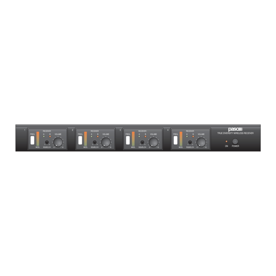
1.2 Pannello frontale ................................ 3
1.3 Pannello posteriore ............................. 3
2.
2.1 Note sull'installazione .......................... 4
2.2 Alimentazione e messa a terra ............ 4
2.3 Note di sicurezza ................................ 4
3.
moduli ricevitori RD200 ....................... 5
4.
4.1 Uscite microfoniche ............................. 6
4.2 Selettore AUX-LINE ............................ 6
4.3 Antenne ............................................. 7
5.
5.1 Accensione ......................................... 9
5.2 Regolazioni ......................................... 9
6.
Caratteristiche tecniche ............ 10
7.
Lista delle parti di ricambio ....... 10
•••
Nel ringraziarVi per aver scelto un prodotto
PASO, vogliamo ricordarVi che la nostra
azienda opera con sistema di qualità
certificato UNI EN ISO 9002. I nostri prodotti
vengono pertanto controllati in ogni fase della
produzione
per
garantire
soddisfazione del Vostro acquisto. Per ogni
evenienza la garanzia coprirà, nell'anno di
validità, eventuali difetti di fabbricazione.
Per il corretto utilizzo di questo prodotto e
per sfruttarne appieno le prestazioni vi
raccomandiamo di leggere e seguire
attentamente le istruzioni d'uso che seguono.
INSTRUCTIONS FOR USE
TABLE OF CONTENTS
1.
1.1 Introduction ....................................... 3
1.2 Front panel ........................................ 3
1.3 Rear panel ......................................... 3
2.
2.1 Notes concerning installation .............. 4
2.3 Safety notes ...................................... 4
3.
Installation
RD 200 receiver modules .................... 5
4.
4.1 Microphone outputs ............................ 6
4.2 AUX-LINE switch ................................. 6
4.3 Antennas ........................................... 7
5.
5.1 Switching on ....................................... 9
5.2 Settings ............................................. 9
6.
Technical specifications ............ 10
7.
List of spare parts ...................... 10
While thanking you for having chosen a PASO
product, we would like to remind you that our
company works according to a Quality System
certified for compliance with ISO 9002
standards. This means that all our products are
la
piena
checked during every phase of manufacturing
in order to guarantee that you will be fully
satisfied with your purchase. At all events, the
guarantee will cover any manufacturing flaws
for the whole year for which it is valid. We
recommend that you read the following
instructions for use carefully in order to exploit
in full the performance of this product and to
avoid any problems.
VHF WIRELESS SYSTEMS
VHF WIRELESS SYSTEMS
•••
MANUEL D'UTILISATION
SOMMAIRE
1.
1.1 Introduction ..................................... 11
1.2 Panneau frontal ............................... 11
1.3 Panneau postérieur .......................... 11
2.
2.1 Notes sur l'installation ....................... 12
2.2 Alimentation et mise à la terre .......... 12
2.3 Notes de sécurité ............................. 12
3.
modules récepteurs RD200 ............... 14
4.
4.1 Sorties micro ..................................... 14
4.2 Selecteur AUX-LINE .......................... 14
4.3 Antennes ......................................... 15
5.
5.1 Allumage .......................................... 17
5.2 Réglages .......................................... 17
6.
Caractéristiques techniques ..... 18
7.
Liste des pièces détachées ....... 18
•••
Vous remerciant d'avoir accordé votre
préférence à un produit PASO, nous tenons à
vous rappeler que nous appliquons à notre
production un Système Qualité certifié ISO
9002. Aussi, pour donner entière satisfaction
à notre clientèle, tous nos produits sont
contrôlés à chaque étape de la production. Ils
sont en outre garantis contre tout défaut de
fabrication pendant une période d'un an. Nous
vous recommandons de lire attentivement les
instructions d'installation et d'utilisation qui
suivent; elles vous permettront d'obtenir le
maximum des prestations offertes par le
produit et en outre d'éviter tout problème.
R234
1
Inhaltsverzeichnis

Verwandte Anleitungen für Paso R234

Inhaltszusammenfassung für Paso R234
-
Seite 1: Inhaltsverzeichnis
••• ••• ••• Nel ringraziarVi per aver scelto un prodotto While thanking you for having chosen a PASO Vous remerciant d’avoir accordé votre PASO, vogliamo ricordarVi che la nostra product, we would like to remind you that our préférence à un produit PASO, nous tenons à... - Seite 2 ••• ••• ••• Wir danken Ihnen für die Wahl eines Wij danken u voor uw keuze van een PASO Les agradecemos que hayan elegido un PASO-Produkts und möchten Sie daran product en herinneren u eraan dat de producto PASO, y aprovechamos la ocasión erinnern, daß...
-
Seite 3: Descrizione Generale
The RD200-Fx receiver modules, which will have to be inserted into appositi vani presenti sul frontale dell’R234, non sono forniti in questa the compartments provided for them on the front panel of the R234, confezione. are not included in this pack. -
Seite 4: Avvertenze Generali
PASO più vicino. IMPORTANTE! IMPORTANT! La PASO declina ogni responsabilità per danni a cose e/o persone derivanti PASO will not accept any liability for damage to property and/or persons dall'uso non corretto dell'apparecchio o da procedure non rispondenti a arising out of incorrect use of the equipment or of procedures that do not quanto riportato sul presente libretto. -
Seite 5: Installazione
VHF frequency range. Per inserire i moduli RD200 all'interno dell'R234, operare come segue: To insert the RD200 modules into the R234, proceed as follows: 1) Con l'aiuto di un cacciavite a lama piatta, far leva sulla fessura presente 1) Insert a flat-bladed screwdriver into the slit on the right side of the... -
Seite 6: Connessioni
CONNESSIONI CONNECTIONS 4.1 USCITE MICROFONICHE 4.1 MICROPHONE OUTPUTS É possibile collegare l'apparecchio al sistema d'amplificazione utilizzando It is possible to connect the equipment to the amplifying system using due diverse modalità: two different procedures: • Collegamento tramite prese CHANNEL 1÷4, a cui è possibile •... -
Seite 7: Antenne
Fig. 4.3.2 NOTA NOTE Nel caso in cui l'R234 venisse If the R234 is installed in a rack, and installato all'interno di un rack, e if it is not desirable to use possible qualora non si volessero utilizzare connections to remote antennas, it... - Seite 8 CONNESSIONI CONNECTIONS 2) Collegare i cavetti d'antenna alle relative prese ‘A’ e ‘B’ [4] poste sul 2) Connect the antenna wires to the appropriate sockets ‘A’ and ‘B’ [4] pannello posteriore (fig. 4.3.4). on the rear panel (Figure 4.3.4). Fig. 4.3.4 3) Inserire infine le antenne telescopiche ed orientarle a seconda delle 3) Lastly, plug in the telescopic antennas and direct them as required necessità...
-
Seite 9: Uso Dell'apparecchio 5.1 Accensione
USO DELL’APPARECCHIO USING THE EQUIPMENT 5.1 ACCENSIONE 5.1 SWITCHING ON Dopo aver effettuato tutti i collegamenti necessari, accendere After making all the necessary connections, turn on the equipment by l’apparecchio premendo il tasto ‘POWER’ [3]. pressing the ‘POWER’ key [3]. Accendere il trasmettitore: sul frontale del ricevitore corrispondente - Switch the transmitter on: one of the LEDs A/B on the front panel of si accenderà... -
Seite 10: Caratteristiche Tecniche
CARATTERISTICHE TECNICHE TECHNICAL SPECIFICATIONS ÷ 4 μV i l i à t i v i ÷ μV v i l 7 μ ) V > = 7 μ ) V ÷ Ω Ω Ω ± ÷ i r t LISTA DELLE PARTI DI RICAMBIO LIST OF SPARE PARTS i l a i v i... -
Seite 11: Description Générale
ALLGEMEINE BESCHREIBUNG 1.1 INTRODUCTION 1.1 EINLEITUNG Le récepteur modulaire R234 a été conçu pour permettre la réception Der modulare Empfänger R234 wurde für den gleichzeitigen Empfang simultanée de signaux transmis par plusieurs micros sans fil (jusqu'à un mehrerer Funkmikrofone entworfen (max. vier Mikrofone). -
Seite 12: Recommandations Générales
ALLGEMEINE HINWEISE 2.1 NOTES SUR L'INSTALLATION 2.1 ANGABEN FÜR DIE INSTALLATION Tous les appareils PASO sont réalisés dans le respect des normes Alle PASO-Geräte werden gemäß den strengsten internationalen internationales de sécurité les plus sévères et dans le respect des Sicherheitsnormen und den EG-Anforderungen gebaut. -
Seite 13: Installation
Verwendung von ein bis vier Mikrofonen im fréquence VHF. Frequenzbereich VHF ermöglichen. Pour mettre en place les modules RD200 à l'intérieur du récepteur R234, Beim Einsetzen der Module RD200 in den Innenraum des R234 ist wie procéder comme suit: folgt vorzugehen: 1) Introduire un tournevis plat dans la fente présente sur le côté... -
Seite 14: Branchements
BRANCHEMENTS ANSCHLÜSSE 4.1 SORTIES MICRO 4.1 MIKROFONAUSGÄNGE Il est possible de brancher l'appareil au système d'amplification en Es bestehen zwei Möglichkeiten, das Gerät an das Verstärkersystem procédant selon deux modalités distinctes: anzuschließen: • Branchement par l'intermédiaire des prises CHANNEL 1÷4, •... -
Seite 15: Antennes
90° 90° Fig./Abb. 4.3.2 NOTE MERKE Dans le cas où le récepteur R234 Bei Rackmontage des R234 und falls serait installé dans un rack et que keine Anschlüsse an entfernt l'on ne souhaiterait pas procéder au liegenden Antennen gewünscht raccordement à... - Seite 16 BRANCHEMENTS ANSCHLÜSSE 2) de raccorder les câbles d'antenne aux prises correspondantes ‘A’ et 2) Schließen Sie die Antennenkabel an die Buchsen ‘A’ und ‘B’ [4] auf dem ‘B’ [4] situées sur le panneau postérieur (fig. 4.3.4). Rückpaneel an (Abb. 4.3.4). Fig./Abb.
-
Seite 17: Fonctionnement De L'appareil
FONCTIONNEMENT DE L'APPAREIL VERWENDUNG DES GERÄTS 5.1 ALLUMAGE 5.1 EINSCHALTEN Une fois effectués tous les branchements nécessaires, allumer l'appareil Nach Herstellung aller erforderlichen Anschlüsse, Schalten Sie das Gerät en appuyant sur la touche ‘POWER’ [3]. ein, indem Sie die Taste ‘POWER’ [3] drücken. Allumer l'émetteur: sur la partie frontale du récepteur correspondant - Einschalten des Senders: auf der Vorderseite des Empfängers leuchten un des témoins ‘A’... -
Seite 18: Caractéristiques Techniques
CARACTÉRISTIQUES TECHNIQUES TECHNISCHE EIGENSCHAFTEN é r ÷ ä r 4 μV i l i é t ÷ μV 7 μ ) V > l ä = 7 μ ) V é é r ÷ é Ω é Ω é Ω ±... -
Seite 19: Algemene Beschrijving
1.1 INTRODUCCIÓN De modulaire ontvanger R234 is zodanig ontworpen dat er gelijktijdig El receptor modular R234 ha sido diseñado para consentir la recepción al meerdere radiomicrofoons ontvangen kunnen worden (maximaal 4). mismo tiempo de varios micrófonos inalámbricos (hasta 4 a lo sumo). -
Seite 20: Algemene Richtlijnen 2.1 Installatievoorschriften
2.1 NOTAS ACERCA DE LA INSTALACIÓN Alle apparaten van PASO worden gebouwd volgens de strengste Todos los aparatos PASO están fabricados conforme a las más severas internationale veiligheidsvoorschriften en voldoen aan de vereisten van normas internacionales de seguridad y según los requisitos de la de Europese Gemeenschap. -
Seite 21: Installatie Van De Rd200 Ontvangermodules
1 y 4 micrófonos inalámbricos en la toestaan in het VHF frequentiebereik. gama de frecuencia VHF. Om de RD200 modules in de R234 te installeren gaat u als volgt te werk: Para introducir los módulos RD200 dentro del R234, efectuar las siguientes operaciones:... -
Seite 22: Aansluitingen 4.1 Microfoonuitgangen
AANSLUITINGEN CONEXIONES 4.1 MICROFOONUITGANGEN 4.1 SALIDAS MICROFÓNICAS Het is mogelijk het apparaat aan te sluiten op het versterkingssysteem. Es posible conectar el aparato al sistema de amplificación utilizando dos Dit kan op twee verschillende manieren: modalidades diferentes: • Aansluiting via de CHANNEL aansluitingen 1÷4, waarmee de •... -
Seite 23: Antennes
Afb./Fig. 4.3.2 OPMERKING NOTA Indien de R234 in een rack wordt En el caso de que el R234 se instalara geïnstalleerd en u geen gebruikt wilt dentro de un rack, y si no se quisieran maken van eventuele verbindingen utilizar eventuales conexiones con met zich op afstand bevindende antenas distantes, será... - Seite 24 AANSLUITINGEN CONEXIONES 2) Verbind de antennekabeltjes met de hiervoor bestemde aansluitingen 2) Conectar los cables de antena con las tomas correspondientes ‘A’ y ‘B’ ‘A’ en ‘B’ [4] op het achterpaneel (afb. 4.3.4). [4] situadas en el panel trasero (fig. 4.3.4). Afb./Fig.
-
Seite 25: Gebruik Van Het Apparaat 5.1 Inschakeling
GEBRUIK VAN HET APPARAAT USO DEL APARATO 5.1 INSCHAKELING 5.1 ENCENDIDO Nadat alle noodzakelijke aansluitingen tot stand zijn gebracht zet u het Después de haber efectuado todas las conexiones necesarias, encender apparaat aan met de toets ‘POWER’ [3]. el aparato presionando el botón ‘POWER’ [3]. Schakel de zender in: op het frontpaneel van de bijbehorende - Encender el transmisor: en el frontal del receptor correspondiente se ontvanger zal één van de led’s ‘A’/’B’... -
Seite 26: Technische Kenmerken
TECHNISCHE KENMERKEN CARACTERÍSTICAS TÉCNICAS ÷ 4 μV ÷ μV 7 μ ) V > ó i ñ ñ = 7 μ ) V ÷ Ω Ω Ω ± ó i ÷ i l e ó i LIJST VERVANGINGSONDERDELEN LISTA DE PIEZAS DE REPUESTO Ó... - Seite 27 NOTA Nel continuo intento di migliorare i propri prodotti, la PASO S.p.A. si riserva il diritto di apportare modifiche ai disegni e alle caratteristiche tecniche in qualsiasi momento e senza alcun preavviso. NOTES PASO S.p.A. strive to improve their products continuously, and therefore reserve the right to make changes to the drawings and technical specifications at any time and without notice.