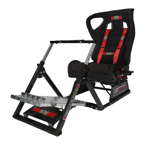
Next Level Racing GTutlimate Bedienungsanleitung
Wheel stand

Verwandte Anleitungen für Next Level Racing GTutlimate

Inhaltszusammenfassung für Next Level Racing GTutlimate
- Seite 1 COMPILED INSTRUCTIONS TO COMPLETE THE NEXT LEVEL RACING GTULTIMATE...
- Seite 2 INSTRUCTION MANUAL FOR NEXT LEVEL RACING WHEEL STAND *If you are using as a FLIGHT STAND please also refer to instructions included with your flight pack For assistance please contact: support@nextlevelracing.com...
- Seite 3 Thank-you for purchasing a GTutlimate If you require any support with your product please contact our friendly team at: support@nextlevelracing.com for a prompt response.
- Seite 4 WHEEL STAND What’s In The Box: NEXT LEVEL RACING WHEEL STAND For assistance please contact: support@nextlevelracing.com...
- Seite 5 WHEEL STAND Step 1: Wheel Support Bar Unpack and unfold the wheel stand out of the box and slide out the wheel support bar. Step 2: After finding the height you prefer for the wheel support bar, screw in 1 x LONG KNOB into the side hole of wheel stand.
- Seite 6 WHEEL STAND Step 3: Screw in 1 x M8 10MM SCREW using M8 ALLEN KEY. Repeat both sides. Step 4: Install WHEEL PLATE to the wheel support bar using the 2 x M6 55MM SCREWS AND NUTS already installed to wheel plate. For assistance please contact: support@nextlevelracing.com...
- Seite 7 WHEEL STAND SKIP IF NOT ATTACHING GEAR SHIFTER Step 5: LEFT HAND GEAR SHIFTER RIGHT HAND GEAR SHIFTER Attach the SHIFTER ARM into either side of the wheel support bar. Tighten in position using SHORT KNOB. Then attach SHIFTER BRACKET onto the SHIFTER ARM and tighten in position using SHORT KNOB.
- Seite 8 WHEEL STAND ADJUSTING PEDAL PLATE & INSTALLING PEDAL STOPPER Step 7: To adjust pedal plate position, loosen the 2 x knobs underneath the pedal plate and slide plate out into preferred position and then tighten knobs. Photo below shows pedal plate when slid out to furthest position. For assistance please contact: support@nextlevelracing.com...
- Seite 9 WHEEL STAND Step 8: Attach PEDAL STOPPER to the holes in pedal plate using the 2 x M6 15MM SCREWS + NUTS ATTACHING YOUR ELECTRONICS Step 9: The 6 x M6 20MM screws provided will suit most electronics on the market.
- Seite 10 WHEEL STAND Step 10: (IGNORE IF YOU ARE NOT USING A THRUSTMASTER T500 WHEEL. EVEN ® IF YOU ARE A T500 OWNER THE BRACKET IS ONLY OPTIONAL AND MANY CUSTOMERS DON’T USE) Use the 2 x M6 50MM SCREWS provide with the OPTIONAL T500 BRACKET to attach the bracket to WHEEL PLATE as well as the T500 wheel.
- Seite 11 FLIGHT STAND PICTURED AS A FLIGHT STAND BELOW USING OPTIONAL FLIGHT PACK. *FLIGHT PACK COMES INCLUDED WITH FLIGHT STAND M8 15MM SCREWS REPEAT BOTH SIDES For assistance please contact: support@nextlevelracing.com...
- Seite 12 WHEEL STAND عم .الخطوة 1: أفرغ املحتويات وأخرج حامل العجلة من العلبة واسحب قضيب دعم العجلة للخارج 1 الخطوة 2: بعد الوصول لالرتفاع املفضل لقضيب دعم حامل العجلة، اربطX LONG KNOB .يف الثقب الجانبي لحامل العجلة، وكرر ذلك مع الجانب اآلخر 1 ...
- Seite 13 WHEEL STAND Krok 1: Rozbalte a rozložte z krabice ocelový stojan a vysuňte ocelovou tyč. Krok 2: Po nastavení preferované výšky tyče zašroubujte 1 X LONG KNOB do postranního otvoru v ocelovém stojanu. Proveďte po obou stranách. Krok 3: Zašroubujte 1 X M8 10MM SCREW pomocí M* ALLEN KEY. Proveďte po obou stranách. Krok 4: Nainstalujte WHEEL PLATE do ocelové...
- Seite 14 WHEEL STAND Stap 1: Haal de stuurstandaard uit de verpakking en ontvouw hem, schuif de stuursteunstang uit. Stap 2: Nadat u de juiste hoogte hebt gevonden voor de stuursteunstang, schroef 1 X LONG KNOB in het gaat aan de zijkant van de stuurstandaard. Herhaal aan beide kanten. Stap 3: Schroef 1 X M8 10MM SCREW in met de M* ALLEN KEY.
- Seite 15 WHEEL STAND Étape 1 : Sortez le support pour volant du carton, dépliez-le chariot mobile et tirez sa barre d’appui. Étape 2 : Après avoir ajusté la barre d’appui à la hauteur désirée, vissez la pièce 1 X LONG KNOB dans le trou latéral du support pour volant.
- Seite 16 WHEEL STAND Step 1: Disimballare ed estrarre il supporto guida dalla scatola, poi fare scorrere la barra di supporto. Step2: Una volta regolata l’altezza della barra, avvitare 1 X LONG KNOB nell’apposito foro del supporto guida. Ripetere su entrambi i lati. Step 3: Avvitare 1 X M8 10MM SCREW usando la M* ALLEN KEY.
- Seite 17 WHEEL STAND Paso 1: Desembale y desplieque la base del volante de la caja y deslice el volante en la barra de soporte. Paso 2: Después de ajustar la altura que desee para la barra de soporte de la base del volante, atornille el 1 X LONG KNOB en el orificio lateral de la base del volante.
- Seite 18 WHEEL STAND Schritt 1: Auspacken Sie und entfalten Sie das Zentrierständer aus der Schachtel und schieben Sie die Radauflageleiste. Schritt 2: Nach dem Ausbilden der Höhe, die Sie für die Auflageleiste des Radstandes bevorzugen, schrau- ben Sie 1 X LONG KNOB in das Seitenloch des Radstandes ein. Wiederholen Sie für beide Seiten. Schritt 3: Schrauben Sie 1 X M8 10MM SCREW mit M* ALLEN KEY.
- Seite 19 INSTRUCTION MANUAL FOR NEXT LEVEL RACING SEAT ADD ON/ GTULTIMATE For assistance please contact: support@nextlevelracing.com www.nextlevelracing.com...
- Seite 20 SEAT ADD ON/ GTULTIMATE What’s In The Box: For assistance please contact: support@nextlevelracing.com www.nextlevelracing.com...
- Seite 21 SEAT ADD ON/ GTULTIMATE Step 1: Centre Bar M8 35MM BOLTS U Shape Bar M8 15MM BOLTS Install SIDE PANELS to U SHAPE BAR using 2 x M8 35MM BOLTS and CENTRE BAR using 2 x M8 15MM BOLTS. STOP IF USING MOTION PLATFORM, REFER TO MOTION PLATFORM Step 2: INSTRUCTIONS BEFORE ATTACHING SEAT Install SIDE PANELS to the GTULTIMATE SEAT using 2 x M8 50MM BOLTS.
- Seite 22 SEAT ADD ON/ GTULTIMATE Step 3: Feed through longest straps of harness through seat headrest holes. Attach 2X CROSS HEAD SCREWS to frame under back of seat. Step 4: Attach support bars from U SHAPE BAR to frame under seat using 2X M6 10MM BOLTS.
- Seite 23 SEAT ADD ON/ GTULTIMATE Step 5: T Pole Attach T POLE under seat using 2X M8 15MM BOLT. (Left or right side depending on gear shifting preference) Step 6: Gear Shifter Adaptor T Pole Gear Shifter Plate Attach GEAR SHIFTER ADAPTOR to T POLE using 2X M8 15MM BOLTS. Attach GEAR SHIFTER PLATE to GEAR SHIFTER ADAPTOR using 1X M8 15MM BOLT.
- Seite 24 SEAT ADD ON/ GTULTIMATE GEAR SHIFTER ADAPTOR reversible to be further or closer. Step 7 (OPTIONAL): If you own the Buttkicker Gamer 2, attach the optional BUTTKICKER ADAPTOR using holes underneath seat framing. Install with 2X M8 35MM BOLTS. For assistance please contact: support@nextlevelracing.com www.nextlevelracing.com...
-
Seite 25: Lumbar Cushion
SEAT ADD ON/ GTULTIMATE LUMBAR CUSHION Step 8: Position LUMBAR CUSHION to support lower back. Feed strap through seat and clip into position. For assistance please contact: support@nextlevelracing.com www.nextlevelracing.com... - Seite 26 SEAT ADD ON/ GTULTIMATE GTULTIMATE SETUP Step 9: Attach WHEEL STAND to SEAT ADD ON using 2X M8 85MM BOLTS. For assistance please contact: support@nextlevelracing.com www.nextlevelracing.com...
- Seite 27 SEAT ADD ON/ GTULTIMATE FLATTENING/ ADJUSTING PEDAL PLATE ANGLE Step 10 (OPTIONAL): For customers that need angle of pedal plate flatter or have high performance pedals that require stronger support Remove M8 BOLT in hinge in middle of pedal plate. Repeat both sides.
- Seite 28 SEAT ADD ON/ GTULTIMATE NEED ASSISTANCE? If you require any support with your product please contact our friendly team at: support@nextlevelracing.com for a prompt response. For assistance please contact: support@nextlevelracing.com www.nextlevelracing.com...
- Seite 29 SEAT ADD ON/ GTULTIMATE Krok 1: Nainstalujte SIDE PANELS na U SHAPE BAR pomocí šroubů 2 x M8 35MM a na CENTRE BAR pomocí šroubů 2 x M8 15MM Krok 2: JESTLIŽE POUŽÍVÁTE MOTION PLATFORM, PŘERUŠTE PRÁCI A PODÍVEJTE SE PŘED PŘIPOJENÍM SEDADLA DO NÁVODU K MOTION PLATFORM.
- Seite 30 SEAT ADD ON/ GTULTIMATE Stap 1: Installeer SIDE PANELS op U SHAPE BAR met 2 x M8 35MM BOLTS en CENTRE BAR met 2 x M8 15MM BOLTS. Stap 2: STOP BIJ GEBRUIK VAN MOTION PLATFORM, ZIE MOTION PLATFORM INSTRUCTIES VOORDAT DE ZETEL WORDT BEVESTIGD. Installeer de SIDE PANELS aan de GTULTIMATE SEAT d.m.v.
- Seite 31 SEAT ADD ON/ GTULTIMATE Étape 1 : Fixez les SIDE PANELS à l’U SHAPE BAR à l’aide des boulons 2 x M8 35MM et la CENTRE BAR en utilisant les boulons 2 x M8 15MM. Étape 2 : ARRÊTEZ L’OPÉRATIOΝ SI VOUS UTILISEZ UΝE MOTION PLATFORM, LISEZ LES IΝSTRUCTIOΝS SUR LA MOTION PLATFORM AVANT DE FIXER LE SIÈGE.
- Seite 32 SEAT ADD ON/ GTULTIMATE Passaggio 1: Istallare i SIDE PANELS sulla U SHAPE BAR utilizzando le VITI 2 x M8 35MM e la CENTRE BAR utilizzando le VITI 2 x M8 15MM. Passaggio 2: IN CASO DI UTILIZZO DELLA MOTION PLATFORM, FARE RIFERIMENTO ALLE ISTRUZIONI PER LA MOTION PLATFORM PRIMA DI COLLEGARE IL SEDILE.
- Seite 33 SEAT ADD ON/ GTULTIMATE Paso 1: Instale los SIDE PANELS en la U SHAPE BAR usando los 2 x TORNILLOS M8 DE 35 MM y la CENTRE BAR usando los 2 x TORNILLOS M8 DE 15 MM. Paso 2: PARE SI UTILIZA LA MOTION PLATFORM, CONSULTA LAS INSTRUCCIONES MOTION PLATFORM ANTES DE INSTALAR EL ASIENTO.
- Seite 34 SEAT ADD ON/ GTULTIMATE Schritt 1: Installieren Sie SIDE PANELS zur U SHAPE BAR mit 2 x M8 35MM BOLZEN und CENTRE BAR mit 2 x M8 15MM BOLZEN. Schritt 2: STOP, WENN SIE MOTION PLATFORM VERWENDEN, WEISEN SIE AUF BEDIENUNGSANLEITUNG DES MOTION PLATFORMS VOR DER ANSCHLIESSEN SITZ VOR DER ANBRINGUNG DES SITZES HIN.
- Seite 35 SEAT ADD ON/ GTULTIMATE FOLDS FOR EASY STORAGE For assistance please contact: support@nextlevelracing.com www.nextlevelracing.com...
- Seite 36 WHEEL STAND FULLY ADJUSTABLE For assistance please contact: support@nextlevelracing.com...
- Seite 37 SEAT ADD ON/ GTULTIMATE AVAILABLE ACCESSORIES TO BUILD THE ULTIMATE COCKPIT For assistance please contact: support@nextlevelracing.com www.nextlevelracing.com...
- Seite 38 BUILD THE ULTIMATE COCKPIT For assistance please contact: support@nextlevelracing.com...