Inhaltsverzeichnis
Werbung
Verfügbare Sprachen
Verfügbare Sprachen
®
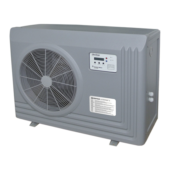
UltraTemp
E
Heat Pump
Pompe à Chaleur
Wärmepumpe
Warmtepomp
Bomba de Calor
Pompa di Calore
Installation Guide
Guide de l'installation
Bedienungsanleitung
Installatiehandleiding
Guia de instalacion
Guide all'installazione
IMPORTANT SAFE TY INSTRUCTIONS
READ AND FOLLOW ALL INSTRUCTIONS
SAVE THESE INSTRUCTIONS
P-INSB-ULTP
(Rev. Feb 2014)
Werbung
Kapitel
Inhaltsverzeichnis

Verwandte Anleitungen für Pentair Ultratemp-E 10


Inhaltszusammenfassung für Pentair Ultratemp-E 10
- Seite 63 Kundendienst Konformitätserklärung Diese Erklärung gilt für UltraTemp-E 8 Bestell-Nr. 460990 UltraTemp-E 10 Bestell-Nr. 460991 UltraTemp-E12 Bestell-Nr. 460992 UltraTemp-E 15 Bestell-Nr. 460993 • • • • •...
-
Seite 64: Wichtige Sicherheitsanweisungen
Inhalt Wichtige Sicherheitsanweisungen ..........................64 Vor der Installation der Wärmepumpe ........................66 Installation und Standort ............................68 Elektrische Anschlüsse und Verdrahtung ........................71 Betrieb der Wärmepumpe ............................74 Bedienteil der Wärmepumpe – Überblick ........................75 Einrichten der UltraTemp-E ............................83 Wartung ..................................85 Technische Daten ..............................87 Wichtige Sicherheitsanweisungen Wichtiger Hinweis für den Monteur: Wichtiger Hinweis für den Benutzer: Vorschriften und Normen... - Seite 65 Konsumenteninformation und Sicherheit Eine erhöhte Wassertemperatur kann gefährlich sein Achtung Schwangere Zu den Auswirkungen einer Hyperthermie gehören: Garantieinformationen...
-
Seite 66: Vor Der Installation Der Wärmepumpe
Vor der Installation der Wärmepumpe Wärmepumpe – Überblick Installationsvoraussetzungen für die Wärmepumpe... -
Seite 67: Allgemeine Funktionen
Allgemeine Funktionen... -
Seite 68: Installation Und Standort
Installation und Standort Wichtigen Warnhinweise und Sicherheitsanweisungen Verpackung Für die Installation benötigte Materialien Standort der Installation... - Seite 69 Ableitung und Kondensation Dachablaufwasser Rasensprenger Platzieren Sie neben der Heizung keine Rasensprenger – diese können Wasser in die Heizung spritzen, wodurch die Garantie erlischt.
- Seite 70 Wasseranschlüsse an der Wärmepumpe ii Pool Wasseraufbereitung Bypass Pumpe Filter Technikraum Kanal...
-
Seite 71: Elektrische Anschlüsse Und Verdrahtung
Elektrische Anschlüsse und Verdrahtung GEFAHR EINES STROMSCHLAGS ODER ELEKTROSCHOCKS Allgemeine Informationen HINWEIS: Zugang zum Kabelfach Stromversorgung Die Versorgung des Stromkreises der Wärmepumpe muss abgeschaltet sein. -
Seite 72: Relaisfernsteuerungen
Relaisfernsteuerungen Hinweis: Die Sollwerte des Bedienteils der Wärmepumpe werden deaktiviert und als N/V angezeigt. Die Temperatureinstellung wird mithilfe eines externen Systems mit Thermostatsteuerung durchgeführt. Um die Fernbedienungsgeräte an die Wärmepumpe anzuschließen, gehen Sie folgendermaßen vor: Hinweis: Legen Sie an die Anschlüsse Spa/Bad/Com keine Spannung an. Ein potenzialfreier Kontakt ist erforderlich! Anschluss der Wärmepumpe an IntelliPool-Automatisierungssysteme mithilfe des RS-485-Anschlusses Hinweis: Die Sollwerte des Bedienteils der Wärmepumpe werden deaktiviert und als N/V angezeigt. - Seite 73 Anschluss der Filtrationspumpe an die UltraTemp Hinweis: Die Schaltschütze sind nicht im Lieferumfang des Wärmepumpe enthalten. Hinweis: Der Schaltschütz muss für eine Eingangsspannung von 24 VAC ausgelegt sein. Die Anschlüsse für Nullleiter und Phase dürfen nicht gekreuzt werden. Andere Klemmen auf dem Anschlussblock...
-
Seite 74: Betrieb Der Wärmepumpe
Betrieb der Wärmepumpe ACHTUNG – VORSICHTSMASSNAHMEN BEI DER ERSTINBETRIEBNAHME Die Poolpumpe muss eingeschaltet sein und Wasser muss durch die Wärmepumpe fließen, damit diese funktioniert. Bei jeder neuen Bad- oder Spa-Installation muss die Filterpumpe bei ausgeschalteter Wärmepumpe lang genug in Betrieb sein, damit das Wasser vollständig gereinigt wird. Dadurch werden sämtliche Überreste der Installation aus dem Wasser entfernt. -
Seite 75: Bedienteil Der Wärmepumpe - Überblick
Bedienteil der Wärmepumpe – Überblick EIN/AUS MENÜAUSWAHL BAD/SPA AUF und AB Pfeiltasten LCD-BILDSCHIRM EIN-Leuchte SERVICE-LEUCHTE... -
Seite 76: Bedienereinrichtungsmenü (Auf Und Ab Pfeiltasten Gleichzeitig Drücken)
Bedienereinrichtungsmenü (AUF und AB Pfeiltasten gleichzeitig drücken) Navigation durch den Bedienereinrichtungsbildschirm 1. Sprache 2. Software Version 3. Startzeit Pumpe 4. Intelli Adresse 5. Temperatureinheit 6. Temp Ausgleich 7. Enteisen 8. Autoset 9. Extend 10. Eingangsschirm Ausgangsschirm 12. Laufz/Zähler 13. Setup verlassen... - Seite 77 Bedienteilmenü (Taste MENÜAUSWAHL drücken) 1. Auto Modus-Bildschirm 2. Bildschirme für Bad- und Spabetrieb 3. Auswahlschirm für Heizung bzw. Kühlung 4. Wärmepumpen-Timer-Bildschirm 5. Relaisfernsteuerung Ein/Aus-Bildschirm Hinweis: Wenn Sie ein RS-485-Kommunikationskabel verwenden, muss der Relaisfernsteuerungsmodus ausgeschaltet sein. 6. AutoSet Ein/Aus-Bildschirm 7. Extend Ein/Aus-Bildschirm 8.
- Seite 78 Temperatureinheit – °C oder °F Wassertemperaturausgleich Sperren des Bedienteils Enteisungszyklus Hinweis: Da der Verdampfer während des Enteisens erwärmt wird, kann es zur Bildung von Wasserdampf sowie erhöhter Produktion von Kondenswasser kommen. Starten und Stoppen der Wärmepumpe...
- Seite 79 Ändern des Sollwerts (Temperatur) Wärmepumpen-Timer Relaisfernsteuerung Im Relaisfernsteuerungsbetrieb wird die Wärmepumpe über eine externe Thermostatregelung gestartet und gestoppt. Das bedeutet, dass die fernbedienten Automatisierungssteuerungen den lokalen Sollwert der Wärme- pumpe überschreiben. Serielle Fernsteuerung (RS-485-Kabel) für IntelliPool Im seriellen Fernsteuerungsbetrieb wird die Wärmepumpe über eine serielle RS-485-Kommunikationsverbindung zu einer IntelliPool-Steuerung gestartet und gestoppt.
- Seite 80 Hinweis: Wenn das RS-485-Kommunikationskabel angeschlossen ist, reagiert die Wärmepumpe nicht auf Befehle der Tasten auf dem Bedienteil mit Ausnahme von Ein/Aus. Für die UltraTemp-Funktionen wird die IntelliPool-Software 4.25 oder höher benötigt. AutoSet So verwenden Sie diese Funktion: So aktivieren Sie die AutoSet-Funktion: Wenn Sie beispielsweise den Bedienteil der Wärmepumpe auf ein Startintervall von 4 Stunden programmieren, die Funktion AutoSet aktiviert ist und Sie eine gewünschte Wassertemperatur von 27 °C haben, kommt es zu folgender Abfolge von Ereignissen:...
- Seite 81 Alarmmeldungen für Timer und Verzögerungen am Bedienfeld Timer für Wassersensor Timer für Neustartverzögerung Timer für Enteisungsverzögerung Verzögerter Pumpenstart Timer für Laufzeit der Wärmepumpe HINWEIS...
-
Seite 82: Alarmmeldungen
Alarmmeldungen WASSERTTEMP HOCH WASSERTEMP NIEDR KEIN DURCHFLUSS FERNB. BAD/SPA TK WASSER KURZS TK WASSER OFFEN TK ENTEIS KURZS; TK ENTEIS OFFEN SPANNUNG NIEDRIG HOCHDRUCK KUHLM. UNTERDR. KUHLM. 5 ALARME BUS COMM PROBLEM Menümeldungen für Timer bzw. Zähler Verwenden Sie die AUF und AB Pfeiltasten, um die verschiedenen Mitteilungen anzuzeigen. Drücken Sie die Taste BAD/SPA, um dieses Menü... -
Seite 83: Einrichten Der Ultratemp-E
Einrichten der UltraTemp-E Installation • Z u m P o o l Z u m P o o l Z u m P o o l Z u m P o o l • • Z u r Z u r Z u r Z u r W ä... - Seite 84 Normaldruck Abnormaler Druck...
-
Seite 85: Wartung
Wartung Wasserchemie Empfohlener Wert Test Überwinterung Inbetriebnahme im Frühling Überprüfung und Wartung... - Seite 86 Überprüfung durch den Eigentümer • • • • • • Professionelle Wartung und Servicierung...
-
Seite 87: Technische Daten
Technische Daten Verdrahtungsplan für UltraTemp-E 08, UltraTemp-E 10 und UltraTemp-E 12 Bedienfeld der Wärmepumpe... -
Seite 88: Verdrahtungsplan Für Ultratemp-E
Verdrahtungsplan für UltraTemp-E 15 Bedienfeld der Wärmepumpe... - Seite 89 Leistungsdaten Modell ULTRATEMP-E 8 ULTRATEMP-E 10 ULTRATEMP-E 12 ULTRATEMP-E 15 Luft Heizleistung 24 °C 70 % RL Eingangsleistung Wasser 20 °C Luft Heizleistung 15 °C 70 % RL Eingangsleistung Wasser 26 °C Luft Heizleistung 24 °C 70 % RL Eingangsleistung Wasser 13 °C...
-
Seite 90: Abmessungen Und Gewicht
Abmessungen und Gewicht... -
Seite 91: Elektrische Anschlüsse
Elektrische Anschlüsse Maximale Kabellänge* pro Abschnitt: Strom- Leitungs- Modell versorgung absicherung 2,5 mm² 4 mm² 6 mm² 10 mm² ULTRATEMP-E 08 ULTRATEMP-E 10 ULTRATEMP-E 12 ULTRATEMP-E 15... -
Seite 92: Ersatzteile
Ersatzteile Illustrierte Bauteilansicht... - Seite 93 Artikel-Nr. Beschreibung Ersatzteil für E - 08 E - 10 E - 12 E - 15 * Nicht abgebildet ** Bei einem Austausch dieses Bauteils muss das Kühlmittel ersetzt werden...
- Seite 192 SAVE THESE INSTRUCTIONS o n q u a l s i a s i m e z z o s e n z a p r e v e n t i v a a u t o r i z z a z i o n e s c r i t t a d i P e n t a i r I n t e r n a t i o n a l S R L...