Burnit WBS 20 Bedienungsanleitung
Inhaltsverzeichnis
Verfügbare Sprachen
Verfügbare Sprachen
Quicklinks
TECHNICAL PASSPORT INSTALLATION and OPERATION MANUAL
TECHNISCHER DATENBLATT MONTAGE- und BEDIENUNGSANLEITUNG
MANUEL TECHNIQUE INSTRUCTIONS pour L'INSTALLATION et L'EXPLOITATION
PASAPORTE TECNICO. INSTRUCCION para МОNTAJE y EXPLOTACION
model:
serial number:
Heizkessel für feste Brennstoffe Serie WBS
MANUALE TECNICO. ISTRUZIONE di MONTAGGIO e USO
Caldaie a combustibile solido serie WBS
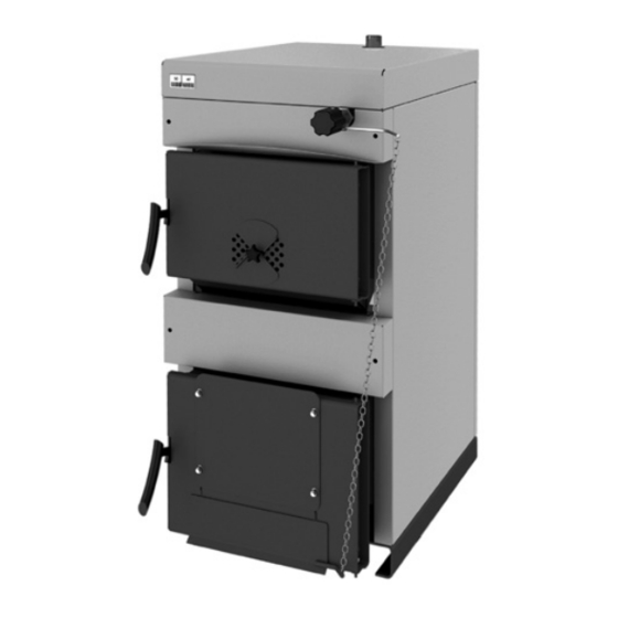
Solid fuel boiler WBS series
Chaudières à combustible solide WBS
de caldera a combustible sólido WBS
Version 0.4.1
EN
DE
FR
ES
IT
Kapitel
Inhaltsverzeichnis

Inhaltszusammenfassung für Burnit WBS 20
- Seite 1 TECHNICAL PASSPORT INSTALLATION and OPERATION MANUAL Solid fuel boiler WBS series TECHNISCHER DATENBLATT MONTAGE- und BEDIENUNGSANLEITUNG Heizkessel für feste Brennstoffe Serie WBS MANUEL TECHNIQUE INSTRUCTIONS pour L’INSTALLATION et L’EXPLOITATION Chaudières à combustible solide WBS PASAPORTE TECNICO. INSTRUCCION para МОNTAJE y EXPLOTACION de caldera a combustible sólido WBS MANUALE TECNICO.
- Seite 13 TECHNISCHER DATENBLATT MONTAGE- und BEDIENUNGSANLEITUNG INHALT Erläuterung von Symbolen und Sicherheitsvorschriften ..............14 1.1. Erläuterung von Symbolen ........................14 1.2. Hinweis für den Montagenraum des Kessels ..................14 1.2.1. Hinweise für den Monteur ........................14 1.2.2. Hinweise für Anlagebenutzer ......................14 1.2.3. Minimale Abstände bei Montage und Entzündbarkeit von Baumaterialien ........15 BESCHREIBUNG VOM ERZEUGNIS ....................... 15 BRENNSTOFFE ............................. 15 TRANSPORTIERUNG VON KESSEL ......................15 KESSEL – LIEFERUNG ...........................
-
Seite 14: Erläuterung Von Symbolen Und Sicherheitsvorschriften
Ausrüstung der Heizanlage mit Sicherungsanlagen. alle Wichtige Besonderheiten bezüglich Anlagennutzung Reinigung aufzuklären. Benutzen Sie nur originale Teile BURNiT Sicherheitsregeln bei der Nutzung vom GEFAHR vor Vergiftung, Erstickung. Der Verbraucher: unzureichende Zustrom von frischer Luft - B enutzen Sie den Heizkessel mit maximaler im Kesselraum kann zu gefährlichem Temperatur von 85°C, zu diesem Zweck prüfen Sie... -
Seite 15: Minimale Abstände Bei Montage Und Entzündbarkeit Von Baumaterialien
TECHNISCHER DATENBLATT MONTAGE- und BEDIENUNGSANLEITUNG Heizkessel oder in seinem Nähe auf. (sieh Schema schreiben die bei der Verbrennung freigesetzten für die minimale Abstände) Gase, einen dreigängigen Weg um. Der - B ewahren Sie keine brennbare Materialien im Wassermantel umfasst gänzlich die Brennkammer Kesselraum auf. -
Seite 16: Transportierung Von Kessel
Gitter geschützt werden. Die Größe der Ventilationsöffnung wird nach der Gewicht, Modelle A, mm B, mm C, mm D, mm Formel berechnet: А = 6,02*Q - wo: А – die Öffnungfläche in сm , Q – WBS 20 1020 1225 Kesselleistung in kW WBS 25 1020 1225 - E ntfernen Sie das Verpackungsmaterial ohne daß... -
Seite 17: Prüfung Der Sicheren Abdichtung Der Türen
TECHNISCHER DATENBLATT MONTAGE- und BEDIENUNGSANLEITUNG Normen und Regeln sein. Der Schornstein soll Vordere Unterplatte mit Isolation genug Zugkraft für die Rauchabführung bei allen Vordere Oberplatte mit Isolation Umständen bereitstellen. Oberer Deckel Isolation Für die richtige Arbeit des Kessels ist die richtige Thermometer Bemessung von dem selben Schornstein erforderlich, Fundament weil von seiner Zugkraft die Verbrennung, die Leistung und das Leben des Kessels abhängt. -
Seite 18: Zusammenfügung Von Wärmeregler - Regler Für Luftstrom
TECHNISCHER DATENBLATT MONTAGE- und BEDIENUNGSANLEITUNG 7.2. Zusammenfügung von Wärmeregler – Regler den Rahmen von 2÷10 bar sein. Die erforderliche für Luftstrom Ergiebigkeit ist wenigstens 12 L/Min. Bauen Sie den Hebel und den Bolzen ab und Schließen Sie der Absicherungswärmeaustauscher schrauben Sie den Regler zum Kessel an, wie auf dem gemäß des hydraulischen Schemas mit Schema bezeichnet ist. Binden Sie ihn mittels der thermostatischen Ventil an. Am Eingang vor dem... -
Seite 19: Schema Zusammenfügung
TECHNISCHER DATENBLATT MONTAGE- und BEDIENUNGSANLEITUNG 3. Wegen Erfrieren 3. Wenn die Heizanlage, einschließlich das Rohrnetz keinen Erfrierenschutz besitzt, empfehlen wir, daß Sie die Heizanlage mit Flüßigkeit mit niedrigem Erfrierenpunkt anfüllen, und Antikorrosionmittel und Antierfrierenmittel benutzen. Die Leistung ist zu schwach 1.Die Zugkraft ist unzureichend 1.Prüfen Sie den Schornsteinzustand und bemessen Sie die Zugkraft. -
Seite 20: Nutzung Des Kessels
TECHNISCHER DATENBLATT MONTAGE- und BEDIENUNGSANLEITUNG 9. NUTZUNG DES KESSELS größerer Ascheanhäufung ist der Raum für die Verbrennung des Brennstoffes unzureichend, und 9.1. Aufladung und Anzündung des Kessels das kann zu Kesselbeschädigung führen, aufs Ganzes Bei der Anfangsanzündung des Kessels bildet sich gesehen. Die reguläre Reinigung ist wichtig für die Kondensat, das danach ausfließt. (es geht nicht um Sicherung der optimalen Leistung und langem Leben eine Kesselhavadie). -
Seite 21: Garantiebedingungen
TECHNISCHER DATENBLATT MONTAGE- und BEDIENUNGSANLEITUNG - B ei Gasabsonderung in der Brennkammer können 10. GARANTIEBEDINGUNGEN Teer und Kondensate (Säuren) entstehen. Dafür Die Garantiebedingungen sind in der Servicekarte wird ein Mischventil montiert, das so reguliert wird, beschrieben, im Satz beigelegt. daß die minimale Temperatur des zurückfließenden Wassers im Kessel 65° С ist. Das verlängert die Kes- sellebenszeit und seine Garantie. Die Arbeitstem- 11. TECHNISCHE CHARAKTERISTIKEN VON KESSEL peratur des Wassers im Kessel soll zwischen 65 ÷ MIT FESTBRENNSTOFF WBS 85°С sein. -
Seite 22: Technische Parameter
TECHNISCHER DATENBLATT MONTAGE- und BEDIENUNGSANLEITUNG 11.2. Technische Parameter Nominalleistung kW Min / Maximale Leistung kW 15÷20 20÷25 25÷30 35÷40 40÷50 50÷70 70÷90 90÷110 Höhe H mm 1145 1145 1145 1145 1145 1285 1285 1285 Breite L/Tiefe D mm 464/870 464/930 524/930 624/930 624/990 624/1110 684/1110 744/1110 Volumen Wassermantel l Volumen Brennkammer l Widerstand... -
Seite 23: Recycling Und Entsorgung
TECHNISCHER DATENBLATT MONTAGE- und BEDIENUNGSANLEITUNG 12. RECYCLING UND ENTSORGUNG Die Metall- sowie NE-Metallteile werden an lizenzierten Sammelstellen zur Verwertung verkauft. Geben Sie das Verpackungsmaterial zur Bearbeitung Sie sollten nicht als Hausmüll behandelt werden. gemäß der örtlichen Vorschriften und Anforderungen. Am Ende des Lebenszyklus jedes Produkts sind die Komponenten entsprechend den gesetzlichen Vorschriften zu entsorgen. Gemäß der Richtlinie 2002/96/EG über Elektro- und Elektronik-Altgeräte wird eine Entsorgung außerhalb des normalen Flusses von festen Haushaltsabfällen gefordert.