Inhaltsverzeichnis
Werbung
Verfügbare Sprachen
Verfügbare Sprachen
Quicklinks
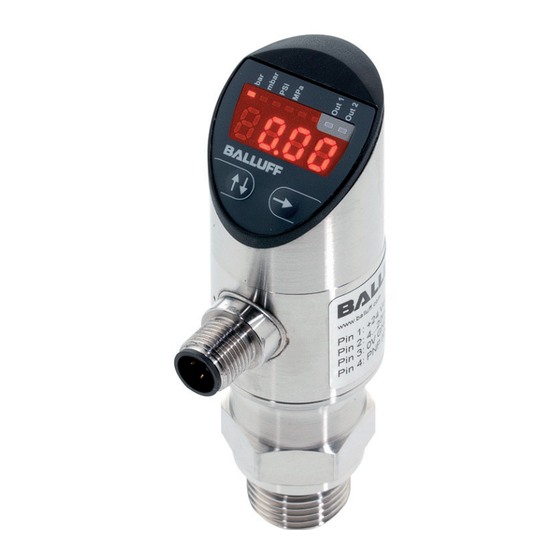
Drucksensoren mit IO-Link
BSP-B... /-V...
EURichtlinie 2004/108/EG (EMVRichtlinie) und EMVGesetz
Fachgrundnormen: EN 6100064 (Emission), EN 6100062 (Störfestigkeit)
Emissionsprüfungen: Funkstörstrahlung EN 55011 Gruppe 1, Klasse A und B
Gültigkeit
Diese Anleitung gilt für folgende Drucksensoren:
–
BSP BxxxxxxxxxxxS1Bxx
–
BSP VxxxxxxxxxxxS1Bxx
HighEnd
Standard
Bestimmungsgemäße Verwendung
Der Drucksensor wurde für die Drucküberwachung von
Gasen oder Flüssigkeiten etwickelt, die zu Edelstahl,
Keramik und FKM kompatibel sind. Je nach Gerät und
mechanischem Anschluss sind Drucksensoren für unter
schiedlichste Anwendungsbereiche geeignet.
Der Drucksensor wird zu seiner Verwendung in eine
Maschine oder Anlage eingebaut. Die einwandfreie Funk
tion gemäß den Angaben in den technischen Daten wird
nur mit Original BALLUFFZubehör zugesichert, die
Verwendung anderer Komponenten bewirkt Haftungsaus
schluss.
Veränderungen am Sensor oder eine nicht bestimmungs
gemäße Verwendung sind nicht zulässig und führen zum
Verlust von Gewährleistungs und Haftungsansprüchen
gegenüber dem Hersteller.
Sicherheitshinweise
Vor Inbetriebnahme ist die Betriebsanleitung
sorgfältig zu lesen!
Diese Sensoren dürfen nicht in Anwendungen
eingesetzt werden, in denen die Sicherheit von
Personen von der Geräte funktion abhängt (kein
Sicherheitsbauteil gem. EUMaschinenrichtlinie).
Die Installation und die Inbetriebnahme sind nur durch
geschultes Fachpersonal zulässig.
Der Betreiber hat die Verantwortung, dass die örtlich
geltenden Sicherheitsvorschriften eingehalten werden.
Insbesondere muss der Betreiber Maßnahmen treffen,
dass bei einem Defekt des Objekterfassungssystems keine
Gefahren für Personen und Sachen entstehen können.
Bei Defekten und nicht behebbaren Störungen des Sen
sors ist dieser außer Betrieb zu nehmen und gegen unbe
fugte Benutzung zu sichern.
www.balluff.com
Download der Betriebsanleitung
Die gleiche Betriebsanleitung erhalten Sie auch im Internet
unter www.balluff.com.
Installation mechanisch
–
Die Drucksensoren immer im druck und stromlosen
Zustand montieren!
HighEnd frontbündig
–
Bei der Montage im Freien oder in feuchter Umgebung
ist Folgendes zu beachten:
Eine Montagelage auswählen, die ein Ablaufen von
Spritz und Kondenswasser erlaubt. Stehende Flüssig
keit an Dichtflächen ist auszuschließen!
Damit keine Feuchtigkeit in den Stecker eindringen
kann, das Gerät nach der Montage unmittelbar elek
trisch anschließen. Anderenfalls den Feuchtigkeitsein
tritt z.B. durch eine passende Schutzkappe verhindern.
Die im Datenblatt angegebene Schutzart gilt für das
angeschlossene Gerät!
Falls die Gefahr der Beschädigung durch Blitzeinschlag
oder Überspannung besteht, einen Überspannungs
schutz zwischen Speisegerät bzw. Schaltschrank und
Gerät anordnen.
–
Bei hydraulischen Systemen das Gerät so positionieren,
dass der Druckanschluss nach oben zeigt (Entlüftung).
–
Beim Einsatz in Dampfleitungen eine Kühlstrecke vorsehen.
–
Das Gerät so montieren, dass es vor direkter Sonnen
ein strahlung geschützt ist. Diese kann die Funktions
fähigkeit des Gerätes beeinträchtigen oder das Gerät
beschädigen.
–
Ein Gerät mit Relativbezug im Gehäuse (kleine Bohrung
neben dem elektrischen Anschluss) so montieren, dass
der für die Messung erforderliche Relativbezug vor
Schmutz und Feuchtigkeit geschützt ist. Falls das
Gerät einer Flüssigkeitsbeaufschlagung ausgesetzt
wird, ist der Luftdruckausgleich durch den Relativbe
zug blockiert. Eine genaue Messung in diesem
Zustand ist nicht möglich. Außerdem kann es zu
Schäden am Gerät kommen.
–
Durch die Montage dürfen keine mechanischen Span
nungen am Druckanschluss auftreten, da diese zu
einer Verschiebung der Kennlinie führen können. Dies
gilt ganz besonders für sehr kleine Druckbereiche
sowie für Geräte mit einem Druckanschluss aus Kunst
stoff.
Achtung!
Der Drucksensor darf keinen hohen Temperatu
ren, schnellen Druckanstiegen über die spezifi
schen Grenzen hinaus ausgesetzt werden
(Grenz werte siehe Technische Daten).
Die empfindliche Membran des frontbündigen
Sensors nicht berühren, sie kann reißen oder
sich deformieren.
deutsch
1
Werbung
Inhaltsverzeichnis

Verwandte Anleitungen für Balluff BSP Bxxx-xxxxx-xxxS1B-series

Inhaltszusammenfassung für Balluff BSP Bxxx-xxxxx-xxxS1B-series
- Seite 1 Maschine oder Anlage eingebaut. Die einwandfreie Funk tion gemäß den Angaben in den technischen Daten wird Falls die Gefahr der Beschädigung durch Blitzeinschlag nur mit Original BALLUFFZubehör zugesichert, die oder Überspannung besteht, einen Überspannungs Verwendung anderer Komponenten bewirkt Haftungsaus schutz zwischen Speisegerät bzw. Schaltschrank und schluss.
-
Seite 2: Drucksensoren Mit Io-Link
Drucksensoren mit IO-Link BSP-B... /-V... Installation mechansich Wichtige Hinweise für die Installation der frontbündi gen Sensoren: Achtung! Die ungeschützte Membrane äußerst vorsichtig behandeln, sie kann leicht beschädigt werden. – Verpackung und Schutzkappe erst kurz vor der Mon tage entfernen, damit die Membrane nicht beschädigt wird. - Seite 3 Bild 5: Maßzeichnung Standard und HighEndDrucksensor, nicht frontbündig Display und Anschlussgehäuse um 320° drehbar Prozessanschluss nach EN 3852 Bild 6: Maßzeichnung frontbündiger Drucksensor bis 50 bar Display und Anschlussgehäuse um 320° drehbar Prozessanschluss nach EN 3852 Bild 7: Maßzeichnung frontbündiger Drucksensor ab 100 bar www.balluff.com deutsch...
-
Seite 4: Installation Elektrisch
Drucksensoren mit IO-Link BSP-B... /-V... Installation mechansich Installation elektrisch Adapter für Prozessanschluss G 1/4" Achtung! Den elektrischen Anschluss nur im druck und Mit den optional lieferbaren Adaptern (Zubehör) können die stromlosen Zustand durchführen. Drucksensoren BSP an unterschiedliche Prozes sanschlüsse angepasst werden. Die Adapter sind getrennt Das Gerät entsprechend der auf dem Typenschild stehen... - Seite 5 ändert der Schaltausgang seinen Zustand nicht sofort bei Erreichen des Schaltereignisses, sondern erst nach Ablauf einer bestimmten frei wählbaren Verzögerungszeit von (0...50 s). Besteht das Schaltereignis nach Ablauf der Verzögerungszeit nicht mehr, ändert sich der Schaltaus gang auch nicht. Bild 12: Verzögerungsfunktion www.balluff.com deutsch...
- Seite 6 Drucksensoren mit IO-Link BSP-B... /-V... Menü Bedienungsanleitung AnzeigeModus Passwortabfrage XXXX PW = 0000 PW ≠ 0000 1. Menü 1 mit der Taste aufrufen. ProgrammierModus 2. Die Werte für den Schalt punkt 1 mit der Taste anzeigen lassen. Der gewählte Wert blinkt. Menü...
- Seite 7 Einstellung des Wertes zur Rückschaltverzöge AnalogAusgang. rungszeit 2 nach Erreichen des Rückschalt punktes 2 (0...50 s einstellbar) Menü 5:6 – Ausgang 1 ou 1 Schaltfunktion des Schaltausgangs: = Hysteresefunktion, Schließer = Hysteresefunktion, Öffner = Fensterfunktion, Schließer = Fensterfunktion, Öffner www.balluff.com deutsch...
- Seite 8 Drucksensoren mit IO-Link BSP-B... /-V... Übersicht der einstellbaren Parameter Menüpunkt Bezeichnung Werkseinstellung eigene Einstellung Menü 1 Schaltpunkt 1/ 80 % SP1 / FH1 FensterHigh 1 des Nenndrucks Menü 2 Rückschaltpunkt 1/ 75 % rP1 / FL1 FensterLow 1 des Nenndruck Menü...
-
Seite 9: Messbereich Wertebereich Multiplikator
Parameter Value out of Range SIOMode 0x8033 Paremeter length overrun 0x8034 Parameter length underrun Balluff Drucksensoren mit IOLink unterstützen sowohl den SIOModus, als auch den IOLink Modus. Event Codes SIOModus (Standard IOModus) Im SIOModus arbeitet der Sensor wie ein normaler Definition Event... - Seite 10 Drucksensoren mit IO-Link BSP-B... /-V... IOLink Interface Parameterdaten Die Parameterdaten des Drucksensors entsprechen dem Smart Sensor Profil. Index Subin Object name Single Value Default Kommentar dex hex 0x02 0x00 System Com 0x81 = Löschen Min/MaxWert Durch Schreiben mands 0x82 = res in den Subindex 0xA0 = Set0 wird die Aktion...
- Seite 11 0x00 Delay Back Switching Time 2 2 Byte 0..500 0xD5 0x00 Min Pressure Value 2 Byte Process Data 0xD6 0x00 Max Pressure Value 2 Byte Process Data 0xD7 0x00 Measure damping 2 Byte 0…1000 in 10 ms steps www.balluff.com deutsch...
-
Seite 12: Umgebungsbedingungen
Drucksensoren mit IO-Link BSP-B... /-V... Technische Daten Elektrische Daten Druck Daten Betriebsspannung U 18...36 V DC BSP nicht frontbündig frontbündig Ausgangsstrom max. 250 mA Relativer Nenndruck Schnittstelle IOLink V1.1 Sensor –1...2 bar 2 bar 2 bar Leerlaufstrom I ≤ 50 mA Sensor –1...10 bar 10 bar 10 bar... - Seite 13 03 = 1 x NPN, NO/NC umschaltbar, 1 x 4...20 mA Variante/Optionen S = IOLink mit SIOMode Subvarinate bezogen auf Variante 1 = Basis Variante Bedienelemente B = Anzeige, 2 Tasten Steckersystem S4 = M12, 4polig Besondere Eigenschaften/Sonderausführung (optional) Z = Allgemeine Sonderausführung T = temperaturbeständig www.balluff.com deutsch...
- Seite 14 Drucksensoren mit IO-Link BSP-B... /-V... Typenschlüssel für Drucksensoren mit digitalen Ausgängen BSP B010 E V 002 D 00 S 1 B S4 Z Physikalische Einheit M = Millibar W = Millibar, Vakuum (ab –1 Bar) B = Bar V = Bar, Vakuum (ab –1 Bar) K = Kilobar...
-
Seite 15: Außerbetriebnahme
Schutzmaßnahmen und entsorgen gungslösung und einem weichen Pinsel oder Schwamm Sie das Gerät sachgerecht. gesäubert werden. Das Gerät ist gemäß der Europäischen Richtlinien 2002/96/EG und 2003/108/EG (Elektro und Elektronik Altgeräte) zu entsorgen. Altgeräte dürfen nicht in den Hausmüll gelangen! www.balluff.com deutsch... - Seite 16 US Service Center CN Service Center Germany Germany China Balluff GmbH Balluff GmbH Balluff Inc. Balluff (Shanghai) trading Co., ltd. Schurwaldstrasse 9 Schurwaldstrasse 9 8125 Holton Drive Room 1006, Pujian Rd. 145. 73765 Neuhausen a.d.F. 73765 Neuhausen a.d.F. Florence, KY 41042 Shanghai, 200127, P.R.
-
Seite 17: Mechanical Installation
If there is a risk of damage from lightning or excess when using original BALLUFF accessories, and use of any voltage, mount overvoltage protection between the other components will void the warranty. - Seite 18 Pressure Sensors with IO-Link BSP-B... /-V... Mechanical installation Important notes for installation of flush-mounted sensors: Caution! Handle the unprotected membrane with the utmost care: it can be easily damaged. – Do not remove the packaging and protective cap until shortly before installation, so that the membrane remains undamaged.
-
Seite 19: Dimensional Drawings
EN 3852 Fig. 6: Dimensional drawing of flush-mounted pressure sensors, up to 50 bar Display and connection housing rotate 320° Process connection per EN 3852 Fig. 7: Dimensional drawing of flush-mounted pressure sensors, starting at 100 bar www.balluff.com English... -
Seite 20: Electrical Installation
Pressure Sensors with IO-Link BSP-B... /-V... Mechanical installation Electrical installation Adapter for process connection G 1/4" Caution! Always depressurize and disconnect pressure Pressure sensors BSP can be adapted to different process sensors from the power supply before establish- connections using adapters (accessories) available as an ing an electrical connection. -
Seite 21: Button Functions
0...50 s has elapsed. If the switching event no longer exists by the time the delay has elapsed, the switching output does not change. Fig. 12: Delay function www.balluff.com English... - Seite 22 Pressure Sensors with IO-Link BSP-B... /-V... Menu Operating instructions Display mode Password prompt XXXX PW = 0000 PW ≠ 0000 1. Open menu 1 by pressing the button. Programming mode 2. Press the button to display the values for switching point 1. The selected value flashes.
- Seite 23 (time range 0...50 seconds) Menu 5:6 – Output 1 ou 1 Switching function of the switching output: = Hysteresis function, NO contact = Hysteresis function, NC contact = Window function, NO contact = Window function, NC contact www.balluff.com English...
-
Seite 24: Factory Settings
Pressure Sensors with IO-Link BSP-B... /-V... Overview of adjustable parameters Menu item Description Factory settings Own setting Menu 1 Switching point 1/ SP1 / FH1 FH 1 of the nominal pressure Menu 2 Return point 1 / rP1 /FL1 FL 1 of the nominal pressure Menu 3 Switching point 2/... -
Seite 25: Io-Link Interface
SIO Mode 0x8033 Parameter length overrun 0x8034 Parameter length underrun Balluff pressure sensors with IO-Link support both SIO Mode and IO-Link Mode. Event codes SIO Mode (standard IO mode) In SIO Mode, the sensor works like a normal pressure Definition... - Seite 26 Pressure Sensors with IO-Link BSP-B... /-V... IO-Link interface Parameterization data The pressure sensor parameter data corresponds to the smart sensor profile. Index Subin- Object name Single Value Default Comment dex hex 0x02 0x00 System com- 0x81 = Deleting Min./Max. value The action is mands 0x82 = res...
- Seite 27 0x00 Delay back switching time 2 2 bytes 0...500 0xD5 0x00 Min pressure value 2 bytes Process data 0xD6 0x00 Max pressure value 2 bytes Process data 0xD7 0x00 Measure damping 2 bytes 0…1000 in 10 ms increments www.balluff.com English...
-
Seite 28: Ambient Conditions
Pressure Sensors with IO-Link BSP-B... /-V... Technical data Pressure data Electrical data BSP, not BSP, Supply voltage U 18...36 V DC flush-mounted flush-mounted Output current max. 250 mA Relative nominal Interface IO-Link V1.1 pressure No-load supply current I max. ≤ 50 mA Sensor –1...2 bar 2 bar 2 bar... -
Seite 29: Connector System
S = IO-Link with SIO Mode Subversions based on main version 1 = Basic variant Operating elements B = Display, 2 buttons Connector system S4 = M12, 4-pin Special characteristics or design (optional) Z = General special design T = Temperature-resistant www.balluff.com English... - Seite 30 Pressure Sensors with IO-Link BSP-B... /-V... Type code for pressure sensors with digital outputs BSP - B010 - E V 002 - D 00 S 1 B - S4 - Z Physical unit M = millibar W = millibar, vacuum (from –1 bar) B = bar V = bar, vacuum (from –1 bar) K = kilobar...
-
Seite 31: Maintenance
Therefore always take sponge. appropriate protective measures and dispose of the device correctly. The device must be disposed of according to European Directives 2002/96/EC and 2003/108/EC (Waste Electrical and Electronic Equipment). Equipment should be disposed of separately from domestic waste! www.balluff.com English... - Seite 32 US Service Center CN Service Center Germany Germany China Balluff GmbH Balluff GmbH Balluff Inc. Balluff (Shanghai) Trading Co., Schurwaldstrasse 9 Schurwaldstrasse 9 8125 Holton Drive Ltd. 73765 Neuhausen a.d.F. 73765 Neuhausen a.d.F. Florence, KY 41042 Room 1006, Pujian Rd. 145.
-
Seite 33: Instalación Mecánica
BALLUFF. La utilización de otros componentes conlleva la alimentación o el armario de distribución y el aparato. exoneración de responsabilidad. - Seite 34 Sensores de presión con IO-Link BSP-B... /-V... Instalación mecánica Advertencias importantes para la instalación de los sensores enrasados en el frontal: ¡Atención! Tratar la membrana desprotegida con el máximo cuidado ya que puede sufrir daños fácilmente. – Retirar el embalaje y la caperuza protectora tan solo justo antes del montaje para evitar que la membrana Adaptador para sufra daños.
- Seite 35 Figura 6: dibujo a escala de sensor de presión enrasado en el frontal hasta 50 bar Carcasa de display y conexión giratoria en 320° Conexión de proceso según EN 3852 Figura 7: dibujo a escala de sensor de presión enrasado en el frontal a partir de 100 bar www.balluff.com español...
-
Seite 36: Instalación Eléctrica
Sensores de presión con IO-Link BSP-B... /-V... Instalación mecánica Instalación eléctrica Adaptador para conexión de proceso G 1/4" ¡Atención! Realizar la conexión eléctrica solo en estado sin presión y sin corriente. Los adaptadores disponibles opcionalmente (accesorios) permiten adecuar los sensores de presión BSP a las diferentes conexiones de proceso. - Seite 37 Si el suceso de actuación ha dejado de existir después teclas al de que haya transcurrido el tiempo de retardo, la salida de mismo conmutación tampoco cambia. tiempo El sensor de presión se configura según el estándar VDMA. Figura 12: función de retardo www.balluff.com español...
-
Seite 38: Instrucciones De Servicio
Sensores de presión con IO-Link BSP-B... /-V... Menú Instrucciones de servicio Modo de indicación Consulta de contraseña XXXX PW = 0000 PW ≠ 0000 1. Abrir el menú 1 con la tecla Modo de programa- ción 2. Mostrar los valores para el punto de actuación 1 con la tecla . - Seite 39 Menú 5:6: salida 1 ou 1 Función de conmutación de la salida de con- mutación: = función de histéresis, contacto NA = función de histéresis, contacto NC = función de ventana, contacto NA = función de ventana, contacto NC www.balluff.com español...
- Seite 40 Sensores de presión con IO-Link BSP-B... /-V... Vista general de los parámetros ajustables Punto de menú Denominación Ajuste de fábrica Ajuste propio Menú 1 Punto de actuación 1/ 80 % SP1 / FH1 VentanaHigh 1 de la presión nominal Menú 2 Punto de reactuación 1/ 75 % rP1 / FL1...
- Seite 41 0x8033 Parameter length overrun 0x8034 Parameter length underrun Los sensores de presión de Balluff con IO-Link soportan tanto el modo SIO como también el modo IO-Link. Códigos de evento Modo SIO (modo IO estándar) En el modo SIO, el sensor funciona como un sensor de Definición...
- Seite 42 Sensores de presión con IO-Link BSP-B... /-V... Interfaz IO-Link Datos de parámetros Los datos de parámetros del sensor de presión corresponden al perfil de Smart Sensor. Index Subin- Object name Single Value Default Observación dex hex 0x02 0x00 System Com- 0x81 = borrar valor mín./máx.
- Seite 43 0x00 Delay Back Switching Time 2 2 bytes 0..500 0xD5 0x00 Min Pressure Value 2 bytes Process Data 0xD6 0x00 Max Pressure Value 2 bytes Process Data 0xD7 0x00 Measure damping 2 bytes 0…1000 in 10 ms steps www.balluff.com español...
-
Seite 44: Datos Técnicos
Sensores de presión con IO-Link BSP-B... /-V... Datos técnicos Datos eléctricos Datos de presión Tensión de servicio U 18...36 V CC BSP no enrasado en enrasado en Corriente de salida máx. 250 mA el frontal el frontal Interfaz IO-Link V1.1 Presión nominal relativa Corriente de vacío I máx. - Seite 45 Variante subordinada con respecto a la variante 1 = variante básica Elementos de control B = indicación, 2 teclas Sistema de conector S4 = M12, 4 polos Características específicas/ejecución especial (opcional) Z = ejecución especial general T = termorresistente www.balluff.com español...
- Seite 46 Sensores de presión con IO-Link BSP-B... /-V... Clave de tipos para sensores de presión con salidas digitales BSP - B010 - E V 002 - D 00 S 1 B - S4 - Z Unidad física M = milibar W = milibar, vacío (a partir de -1 bar) B = bar V = bar, vacío ( partir de -1 bar) K = kilobar...
-
Seite 47: Mantenimiento
El aparato debe desecharse según las directivas europeas 2002/96/CE y 2003/108/CE (residuos de aparatos eléctri- cos y electrónicos). ¡Los aparatos residuales no deben echarse a las basuras domésticas! www.balluff.com español... - Seite 48 Centro de servicios CN globales Alemania EE. UU. China Balluff GmbH Alemania Balluff Inc. Balluff (Shanghai) trading Co., ltd. Schurwaldstrasse 9 Balluff GmbH 8125 Holton Drive Room 1006, Pujian Rd. 145. 73765 Neuhausen a.d.F. Schurwaldstrasse 9 Florence, KY 41042 Shanghai, 200127, P.R. China Teléfono + 49 7158...
-
Seite 49: Installation Mécanique
Contrôles en matière d'émissions : Rayonnement de signaux parasites EN 55011 groupe 1, classes A et B Validité Téléchargement de la notice d'utilisation Les présentes instructions sont valables pour les capteurs Vous pouvez télécharger la même notice d'utilisation sur de pression suivants : Internet, à l'adresse www.balluff.com. – BSP Bxxx-xxxxx-xxxS1B-xx – BSP Vxxx-xxxxx-xxxS1B-xx Installation mécanique Attention ! Le capteur de pression ne doit être exposé... - Seite 50 Capteurs de pression avec IO-Link BSP-B... /-V... Installation mécanique Remarques importantes concernant l'installation des capteurs affleurant la face avant : Attention ! Manipuler la membrane non protégée avec une très grande précaution, celle-ci pouvant être facilement endommagée. – Retirer l'emballage et le capuchon de protection juste avant le montage uniquement, afin de ne pas endom- Adaptateur pour raccorde- mager la membrane.
-
Seite 51: Plans Cotés
Figure 6 : Plan coté capteur de pression affleurant, jusqu'à 50 bar Boîtiers d'affichage et de raccordement pivotants sur 320° Raccordement au processus selon EN 3852 Figure 7 : Plan coté capteur de pression affleurant, jusqu'à 100 bar www.balluff.com français... - Seite 52 Capteurs de pression avec IO-Link BSP-B... /-V... Installation mécanique Installation électrique Attention ! Adaptateur pour raccordement au processus G 1/4" Le raccordement électrique doit uniquement être réalisé à l'état hors pression et hors ten- Les adaptateurs (accessoires) fournis en option permettent sion.
- Seite 53 Le capteur de pression est configuré selon la norme déterminée, librement définissable entre (0...50 s). Si, VDMA. après l'écoulement de la temporisation, l'événement de commutation n'est plus présent, la sortie de commutation ne change pas d'état. Figure 12 : Fonction temporisation www.balluff.com français...
-
Seite 54: Instructions D'utilisation
Capteurs de pression avec IO-Link BSP-B... /-V... Menu Instructions d'utilisation Mode d'affichage Saisie du mot de passe XXXX PW = 0000 PW ≠ 0000 1. Appeler le menu 1 à l'aide de la touche Mode de program- mation 2. Afficher les valeurs pour le point de consigne 1 à... - Seite 55 Menu 5 :6 – Sortie 1 ou 1 Fonction de commutation de la sortie : = fonction hystérésis, contact à fermeture = fonction hystérésis, contact à ouverture = fonction fenêtre, contact à fermeture = fonction fenêtre, contact à ouverture www.balluff.com français...
- Seite 56 Capteurs de pression avec IO-Link BSP-B... /-V... Aperçu des paramètres réglables Commande de menu Désignation Réglage usine Réglage personnalisé Menu 1 Point de consigne haut 1/ 80 % SP1 / FH1 FenêtreHigh 1 de la pression nominale Menu 2 Point de consigne bas 1/ 75 % rP1 / FL1 FenêtreLow 1...
- Seite 57 0x8033 Paremeter length overrun 0x8034 Parameter length underrun Capteurs de pression Balluff avec prise en charge IO-Link et mode SIO, ainsi que mode IO-Link. Codes d’événements Mode SIO (Mode IO standard) En mode SIO, le capteur fonctionne comme un capteur de...
- Seite 58 Capteurs de pression avec IO-Link BSP-B... /-V... Interface IO-Link Données de paramétrage Les données de paramétrage du capteur de pression correspondent au profil Smart Sensor. Index Subin- Object name Single Value Default Commentaire dex hex 0x02 0x00 System Com- 0x81 = effacement valeur min./max. L'action est mands 0x82 = res...
- Seite 59 0x00 Delay Back Switching Time 2 2 octets 0..500 0xD5 0x00 Min Pressure Value 2 octets Process Data 0xD6 0x00 Max Pressure Value 2 octets Process Data 0xD7 0x00 Measure damping 2 octets 0…1000 in 10 ms steps www.balluff.com français...
- Seite 60 Capteurs de pression avec IO-Link BSP-B... /-V... Caractéristiques techniques Caractéristiques électriques Caractéristiques de pression Tension d'emploi U 18...36 V DC BSP non affleurant affleurant Courant de sortie max. 250 mA Pression nominale relative Interface IO-Link V1.1 Capteur –1...2 bar 2 bar 2 bar Courant à...
- Seite 61 1 = variante de base Eléments de commande B = affichage, 2 touches Système de connecteur S4 = M12, à 4 pôles Caractéristiques particulières / version spéciale (en option) Z = version spéciale générale T = résistant à la température www.balluff.com français...
- Seite 62 Capteurs de pression avec IO-Link BSP-B... /-V... Code de type pour les capteurs de pression avec sorties numériques BSP - B010 - E V 002 - D 00 S 1 B - S4 - Z Unité physique M = millibar W = millibar, vide (à...
- Seite 63 L'appareil doit être rebuté conformément aux directives éponge douce. européennes 2002/96/CE et 2003/108/CE (appareils électriques et électroniques usagés). Les appareils usagés ne doivent pas parvenir dans les ordures ménagères ! www.balluff.com français...
- Seite 64 Centre de service US Centre de service CN Allemagne Allemagne Chine Balluff GmbH Balluff GmbH Balluff Inc. Balluff (Shanghai) Trading Co., Ltd. Schurwaldstraße 9 Schurwaldstraße 9 8125 Holton Drive Room 1006, Pujian Rd. 145. 73765 Neuhausen a.d.F. 73765 Neuhausen a.d.F. Florence, KY 41042 Shanghai, 200127, P.R.
-
Seite 65: Installazione Meccanica
Dati tecnici, verrà assicurato esclusi- contro le sovratensioni fra l'alimentatore e/o l'armadio vamente con accessori originali BALLUFF; l'utilizzo di altri elettrico e l'apparecchio. componenti comporterà l'esclusione di responsabilità. –... - Seite 66 Sensori di pressione con IO-Link BSP-B... /-V... Installazione meccanica Avvertenze importanti per l’installazione dei sensori a filo sul lato frontale: Attenzione! Trattare la membrana non protetta con estrema cautela, può essere facilmente danneggiata. – Rimuovere imballaggio e calotta protettiva poco prima del montaggio, in modo da non danneggiare la mem- brana.
-
Seite 67: Disegni Quotati
Fig. 6: Disegno quotato sensore di pressione a filo sul lato frontale fino a 50 bar Alloggiamento per display e custodia di collegamento ruotabile di 320° Collegamento di processo secondo EN 3852 Fig. 7: Disegno quotato sensore di pressione a filo sul lato frontale a partire da 100 bar www.balluff.com italiano... -
Seite 68: Installazione Elettrica
Tramite gli adattatori disponibili su richiesta come acces- elettrica. sori, i sensori di pressione Balluff BSP si possono adattare a collegamenti di processo di tipi diversi. Gli adattatori andranno ordinati separatamente. Collegare elettricamente l'apparecchio attenendosi alle Adattatori per ulteriori collegamenti di processo su richiesta. - Seite 69 è più tasti presente, l'uscita di commutazione non cambierà a sua volta. Il sensore di pressione andrà conFig.to secondo lo stan- dard VDMA. Fig. 12: Funzione di ritardo www.balluff.com italiano...
- Seite 70 Sensori di pressione con IO-Link BSP-B... /-V... Menu Manuale d'uso Modalità visualizzazione Richiesta password XXXX PW = 0000 PW ≠ 0000 1. Richiamare il menu 1 premendo il tasto . Modalità di program- mazione 2. Visualizzare i valori del punto di commutazione 1 premendo il tasto .
- Seite 71 2 (impostabile da 0 a 50 s) Menu 5:6 – Uscita 1 ou 1 Funzione di commutazione dell'uscita di com- mutazione: = funzione di isteresi, contatto NO = funzione di isteresi, contatto NC = funzione finestra, contatto NO = funzione finestra, contatto NC www.balluff.com italiano...
- Seite 72 Sensori di pressione con IO-Link BSP-B... /-V... Panoramica dei parametri regolabili Voce del menu Denominazione Impostazione di fabbrica Impostazione personale Menu 1 Punto di commutazione 1/ 80 % SP1 / FH1 FinestraHigh 1 della pressione nominale Menu 2 Punto di ricommutazione 1/ 75 % rP1 / FL1 FinestraLow 1...
- Seite 73 0x8033 Paremeter length overrun 0x8034 Parameter length underrun I sensori di pressione Balluff con IO-Link supportano sia la modalità SIO, sia la modalità IO-Link. Event Codes Modalità SIO (Modalità IO Standard) Nella modalità SIO il sensore lavora come un normale...
- Seite 74 Sensori di pressione con IO-Link BSP-B... /-V... IO-Link Interface Dati parametri I dati parametri del sensore di pressione corrispondono al profilo Smart Sensor. Index Subin- Object name Single Value Default Commento dex hex 0x02 0x00 System Com- 0x81 = Cancellazione valore Min/Max L'azione viene mands 0x82 = res...
- Seite 75 0x00 Delay Back Switching Time 2 2 byte 0..500 0xD5 0x00 Min Pressure Value 2 byte Process Data 0xD6 0x00 Max Pressure Value 2 byte Process Data 0xD7 0x00 Measure damping 2 byte 0…1000 in 10 ms steps www.balluff.com italiano...
- Seite 76 Sensori di pressione con IO-Link BSP-B... /-V... Dati tecnici Dati elettrici Dati di pressione Tensione d'esercizio U 18...36 V DC BSP non a BSP a filo sul filo sul lato lato frontale Corrente di uscita max. 250 mA frontale Interfaccia IO-Link V1.1 Pressione nominale relativa Corrente a vuoto I...
- Seite 77 Sottovariante riferita alla variante 1 = variante base Elementi di comando B = indicatore, 2 tasti Sistema d'innesto S4 = M12 a 4 poli Caratteristiche particolari/Versione speciale (su richiesta) Z = versione speciale generica T = resistente alle alte temperature www.balluff.com italiano...
- Seite 78 Sensori di pressione con IO-Link BSP-B... /-V... Codice identificativo per sensori di pressione con uscite digitali BSP - B010 - E V 002 - D 00 S 1 B - S4 - Z Unità di misura fisica M = millibar W = millibar, vuoto (a partire da –1 bar) B = bar V = bar, vuoto (a partire da –1 bar)
-
Seite 79: Manutenzione
L'apparecchio andrà smaltito nel rispetto delle Direttive Europee 2002/96/CE e 2003/108/CE (Rifiuti di apparec- chiature elettriche ed elettroniche). I rifiuti di apparecchia- ture andranno mantenuti separati dai rifiuti domestici. www.balluff.com italiano... - Seite 80 US Service Center CN Service Center Germania Germania Cina Balluff GmbH Balluff GmbH Balluff Inc. Balluff (Shanghai) Trading Co. Ltd. Schurwaldstrasse 9 Schurwaldstrasse 9 8125 Holton Drive Room 1006, Pujian Rd. 145. 73765 Neuhausen a.d.F. 73765 Neuhausen a.d.F. Florence, KY 41042 Shanghai, 200127, P.R.