
Verwandte Anleitungen für LEGRAND 3 109 53


Inhaltszusammenfassung für LEGRAND 3 109 53
- Seite 1 3 109 53 Maintenance Bypass Switch Installation Manual • Installationsanleitung Part. LE09522AB-09/18-01 GF...
- Seite 2 3 109 53 Maintenance Bypass Switch ENGLISH DEUTSCH...
-
Seite 3: Inhaltsverzeichnis
3 109 53 Maintenance Bypass Switch Index 1 Introduction 1.1 Overview 1.2 Guarantee terms 2 Safety regulations 3 Installation Introduction Front panel Package content Rack Mount Configuration Tower Configuration Preliminary operations 3.6.1 Procedure for Daker DK Plus 1000-2000 VA 3.6.2 Procedure for Daker DK Plus 3000 VA... -
Seite 4: Introduction
The maintenance bypass switch 3 109 53 must be used only with the UPS Daker DK Plus 1000 VA - 2000 VA - 3000 VA and Keor LP 1000 VA - 2000 VA - 3000 VA manufactured by LEGRAND. The purpose of this manual is to provide necessary indications to install and use safely the maintenance bypass switch. -
Seite 5: Guarantee Terms
Legrand. Any unauthorized opening or repair completely cancels all liabilities and the rights to replacement and guarantees. Use only Legrand brand accessories. DANGER The maintenance bypass switch 3 109 53 can only be installed with the UPS completely SWITCHED OFF and UNPLUGGED FROM THE MAINS. - Seite 6 In case of problems with the maintenance bypass switch, the manual must always be consulted to find out how to solve them. If the problem persists, contact the LEGRAND Technical Service Assistance which will provide all the instructions on what to do.
-
Seite 7: Installation
3 109 53 Maintenance Bypass Switch 3 Installation Introduction There are two operation modes offered by the Maintenance Bypass Switch (MTBS). 1 - UPS MODE (UPS available): when the MTBS works on UPS mode, the UPS supply directly the loads. -
Seite 8: Front Panel
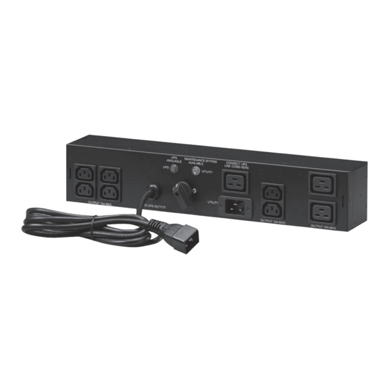
3 Installation Front panel UPS output power cord: connect to the UPS output sockets Input Socket: connect to the mains socket CAM SWITCH: Maintenance Bypass Switch Lamps: they indicate the presence of the UPS and of the mains 5- 6. Load Sockets: connect to the loads UPS Input Socket: connect to the UPS Input... -
Seite 9: Package Content
3 109 53 Maintenance Bypass Switch Package content... -
Seite 10: Rack Mount Configuration
3 Installation Rack Mount Configuration Step 1 Step 2 Step 3... -
Seite 11: Tower Configuration
3 109 53 Maintenance Bypass Switch Tower Configuration Step 1 Step 2... -
Seite 12: Preliminary Operations
3 Installation Preliminary operations 1. Shut down the loads connected to the UPS and remove the output cable of the UPS. 2. Turn off the UPS and remove the input power cord of the UPS from the wall socket. 3. Install a utility circuit breaker of max 20 A – curve C for input wiring. 4. -
Seite 13: Procedure For Daker Dk Plus 1000-2000 Va
3 109 53 Maintenance Bypass Switch 3.6.1 Procedure for Daker DK Plus 1000-2000 VA C1 = cable IEC320 C19-20 C2 = cable IEC320 C13-C14 C3 = cable IEC320 C14-C19 C4 = cable IEC320 C13-C20 C5 = power cord Schuko - IEC320 C19... - Seite 14 3 Installation C1 = cable IEC320 C19-20 C2 = cable IEC320 C13-C14 C3 = cable IEC320 C14-C19 C4 = cable IEC320 C13-C20 C5 = power cord Schuko - IEC320 C19...
-
Seite 15: Procedure For Daker Dk Plus 3000 Va
3 109 53 Maintenance Bypass Switch 1. Plug the input power cord C5 to the input socket of the MTBS [2] and then to the mains socket. The orange lamp of the MTBS [4] will light up. DANGER Hazardous voltages are now present in the MTBS. - Seite 16 3 Installation C1 = cable IEC320 C19-20 C2 = cable IEC320 C13-C14 C5 = power cord Schuko - IEC320 C19 1. Plug the input power cord C5 to the input socket of the MTBS [2] and then to the mains socket. The orange lamp of the MTBS [4] will light up.
-
Seite 17: Operations
3 109 53 Maintenance Bypass Switch 4 Operations Make sure to switch the operating modes according to the following procedures: 1. UPS MODE UTILITY MODE (Maintenance bypass) Step 1: Make sure the orange lamp of the MTBS is lit. If not, refer to the troubleshooting section. -
Seite 18: Troubleshooting
5 Troubleshooting If the MTBS does not operate normally, consult the following table. If the problem cannot be solved, contact the LEGRAND Technical Support Service. PROBLEM SOURCE OF THE PROBLEM SOLUTION Verify if the external circuit breaker has tripped. In this case, reset it. -
Seite 19: Technical Specifications
3 109 53 Maintenance Bypass Switch 6 Technical specifications 3 109 53 General characteristics Net Weight (kg) Dimensions: W×D×H (mm) 87 × 77 × 440 Ambient specifications Operating temperature range 0°C to +40°C (+32°F to +104°F) 20%-80% Operating relative humidity range... - Seite 21 3 109 53 Wartungs-Bypass Schalter 1 Einführung 1.1 Übersicht 1.2 Garantiebedingungen 2 Sicherheitshinweise 3 Installation Einführung Bedieneinheit Verpackungsinhalt Rack Konfiguration Tower Konfiguration Vorbereitende Arbeiten 3.6.1 Prozedur für Daker DK Plus 1000 – 2000VA 3.6.2 Prozedur für Daker DK Plus 3000VA 4 Umschaltungen 5 Problemlösung...
-
Seite 22: Einführung
Lesen Sie das Handbuch aufmerksam durch, bevor Sie das Gerät benutzen. ACHTUNG Der Wartungsbypass-Schalter 3 109 53 kann nur mit den LEGRAND USV-Anlagen Daker DK Plus 1000 VA – 2000 VA -3000VA und Keor LP 1000 VA – 2000 VA – 3000 VA benutzt werden. -
Seite 23: Garantiebedingungen
Die Bedingungen der Garantie können je nach Land variieren, in dem der Wartungsbypass 3 109 53 verkauft wird. Überprüfen Sie die Gültigkeit und Dauer mit dem lokalen Vertreter von LEGRAND. Der Hersteller übernimmt keinerlei Haftung, weder direkt noch indirekt, in folgenden Fällen: - Nichtbeachtung der Installationsanweisungen und Verwendung des Geräts auf eine andere Wei-... -
Seite 24: Sicherheitshinweise
Anleitung lesen, den produktspezifischen Montageort beachten. Das Gerät vorbehaltlich be- sonderer, in der Betriebsanleitung angegebener Hinweise nicht öffnen, zerlegen, beschädigen oder abändern. Alle Produkte von LEGRAND dürfen ausschließlich von durch LEGRAND geschul- tes und anerkanntes Personal geöffnet und repariert werden. Durch unbefugte Öffnung oder Reparatur erlöschen alle Haftungs-, Ersatz- und Gewährleistungsansprüche. - Seite 25 3 109 53 Wartungs-Bypass Schalter GEFAHR Der Wartungsbypass Schalter 3 109 53 kann nur mit den LEGRAND USV-Anlagen benutzt werden. Zum Anschluss muss die USV-Anlage komplett ausgeschaltet und von der Netzspannung getrennt sein. ACHTUNG Bei nichteinhalten der Installations- und Betriebsanleitung kann die USV, der Wartungsbypass Schalter oder die angeschlossenen Verbraucher beschädigt werden.
-
Seite 26: Installation
3 Installation Einführung Der Wartungsbypass Schalter (MTBS) bietet zwei Betriebsarten 1 - USV MODUS (USV Betrieb): In dieser Betriebsart arbeitet der MTBS im USV MODUS, die USV versorgt die Last direkt. 2 - NETZ MODUS (Bypass Betrieb): In dieser Betriebsart arbeitet der MTBS in NETZ MODUS, das Netz versorgt die Last direkt. -
Seite 27: Bedieneinheit
3 109 53 Wartungs-Bypass Schalter Bedieneinheit USV Ausgangskabel: Verbindung zum Ausgangsstecker der USV. Eingangsstecker: Verbindung zur Netzsteckdose Drehschalter: Wartungsbypass Schalter Lampen: Zur Anzeige der USV und Netzspannung 5- 6. Ausgangssteckdosen: Zum Anschluss der Last USV Eingangssteckdose: Verbindung zum Eingangsstecker der USV... -
Seite 28: Verpackungsinhalt
3 Installation Verpackungsinhalt... -
Seite 29: Rack Konfiguration
3 109 53 Wartungs-Bypass Schalter Rack Konfiguration Schritt 1 Schritt 2 Schritt 3... -
Seite 30: Tower Konfiguration
3 Installation Tower Konfiguration Schritt 1 Schritt 2... -
Seite 31: Vorbereitende Arbeiten
3 109 53 Wartungs-Bypass Schalter Vorbereitende Arbeiten 1. Ausschalten der angeschlossenen Lasten und alle Ausgangskabel entfernen 2. USV-Anlage ausschalten und das Eingangskabel entfernen. 3. Überprüfung der Installation, die Eingangsnetzsicherung darf max. 20A (Charakteristik C) be- tragen. 4. Der Drehschalter (Wartungsbypass Schalter) ist auf der Position «UTILITY»... -
Seite 32: Prozedur Für Daker Dk Plus 1000-2000 Va
3 Installation 3.6.1 Prozedur für Daker DK Plus 1000-2000 VA C1 = Kabel IEC320 C19-20 C2 = Kabel IEC320 C13-C14 C3 = Kabel IEC320 C14-C19 C4 = Kabel IEC320 C13-C20 C5 = Anschlusskabel Schuko - IEC320 C19... - Seite 33 3 109 53 Wartungs-Bypass Schalter C1 = Kabel IEC320 C19-20 C2 = Kabel IEC320 C13-C14 C3 = Kabel IEC320 C14-C19 C4 = Kabel IEC320 C13-C20 C5 = Anschlusskabel Schuko - IEC320 C19...
-
Seite 34: Prozedur Für Daker Dk Plus 3000Va
3 Installation 1. Verbinden Sie das Anschlusskabel C5 mit der Eingangssteckdose des MTBS [2] und der Netz- steckdose. Sofern Spannung vorhanden ist leuchtet die orange Lampe des MTBS [4] auf. GEFAHR Nun steht am MTBS eine gefährliche Spannung an. 2. Verbinden Sie die Kabel C4 und C1 mit der Eingangssteckdose der USV und der USV Eingangs- steckose des MTBS [7] GEFAHR Nun steht an der USV eine gefährliche Spannung an. - Seite 35 3 109 53 Wartungs-Bypass Schalter C1 = Kabel IEC320 C19-20 C2 = Kabel IEC320 C13-C14 C5 = Anschlusskabel Schuko - IEC320 C19 1. Verbinden Sie das Anschlusskabel C5 mit der Eingangssteckdose des MTBS [2] und der Netz- steckdose. Sofern Spannung vorhanden ist leuchtet die orange Lampe des MTBS [4] auf.
- Seite 36 4 Umschaltungen Halten sie die Schaltreihenfolgen wie unten beschrieben ein: 1. USV Betrieb NETZ BETRIEB (Bypass Betrieb) Schritt 1: Überprüfen Sie, dass die orange Lampe am MTBS leuchtet. Falls nicht sehen Sie im Kapitel Störungsbehebung nach. Schritt 2: Schalten Sie die USV auf den Bypass-Modus gemäss Bedienungsanleitung ein. Schritt 3: Drehen Sie den Drehschalter (Wartungsbypass Schalter) von der Position «UPS»...
-
Seite 37: Problemlösung
3 109 53 Wartungs-Bypass Schalter 5 Problemlösung Sollte der MTBS nicht wie gewünscht funktionieren, kann die Störung anhand der nachfolgenden Tabelle behoben werden. Sollte das Problem weiterhin bestehen, wenden Sie sich an den technischen Support von LEGRAND. HINWEIS DIAGNOSTIK LÖSUNG Überprüfen ob die externe... -
Seite 38: Technische Spezifikationen
6 Technische Spezifikationen 3 109 53 Allgemeine Daten Nettogewicht (kg) Abmessungen B x H x T (mm) 440 × 87 (2U) × 77 Umgebungsbedingungen Betriebstemperatur 0°C to +40°C (+32°F to +104°F) Relative Feuchtigkeit bei Betrieb 20%-80% (nicht kondensierend) Lagerungstemperatur -20°C to +40°C (-4°F to +104°F) Betriebshöhe... - Seite 40 Legrand se réserve le droit de modifier à tout moment le contenu de cet imprimé et de communiquer, Legrand reserves at any time the right to modify the contents of this booklet and to communicate, sous n’importe quelle forme et modalité, les changements apportés.