thyracont VD9 Betriebsanleitung
Digitales vakuum anzeigeund
regelgerät

Verwandte Anleitungen für thyracont VD9


Inhaltszusammenfassung für thyracont VD9
- Seite 1 Digitales Vakuum Anzeige- und Regelgerät Digital Vacuum Display and Control Unit Betriebsanleitung Operating Instructions...
-
Seite 2: Inhaltsverzeichnis
Inhalt Hinweise für Ihre Sicherheit ..............3 Das Anzeige- und Regelgerät VD9 ............4 Zur Orientierung ................... 4 Lieferumfang ..................4 Produktbeschreibung ................5 Installation ....................7 Hinweise zur Installation ..............7 Netzanschluss ..................7 Transmitter-Anschluss 0-10 V .............. 7 Transmitter-Anschluss 4-20 mA ............ -
Seite 3: Hinweise Für Ihre Sicherheit
Ihrer Anlage ausgehen Beachten Sie die Sicherheits- und Unfall-Verhütungsvorschriften Prüfen Sie regelmäßig die Einhaltung aller Schutzmaßnahmen Installieren Sie das VD9 unter Einhaltung der entsprechenden Umgebungsbedingun- gen; die Schutzart ist IP20, d.h. die Geräte sind geschützt gegen Eindringen von Fremdkörpern Beachten Sie beim Umgang mit den verwendeten Prozessmedien die einschlägigen Vorschriften und Schutzmaßnahmen... -
Seite 4: Das Anzeige- Und Regelgerät Vd9
2 Das Anzeige- und Regelgerät VD9 2.1 Zur Orientierung Diese Betriebsanleitung ist gültig für Produkte mit den Artikelnummern VD9S2. Sie finden die Artikelnummer auf dem Typenschild. Technische Änderungen ohne vorherige Anzeige sind vorbehalten. 2.2 Lieferumfang Zum Lieferumfang gehören: VD9 Anzeige- und Regelgerät Netzkabel Gegenstecker f. -
Seite 5: Produktbeschreibung
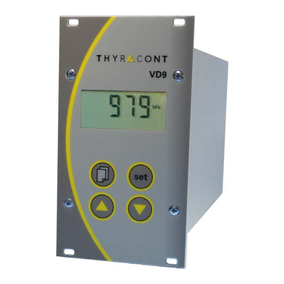
2.3 Produktbeschreibung Das VD9S2 dient zum Anzeigen und Regeln von Absolutdruck in Verbindung mit Thyracont Vakuum-Transmittern mit Signalausgang 4-20mA oder 0-10V. Über die serielle Schnittstelle kann der Regler vom PC aus gesteuert werden. LCD Anzeige Taste Menu Pfeiltasten auf/ab Taste Set Signaleingang 4-20mA f. - Seite 6 Bestimmungsgemäße Verwendung Das VD9 dient in Verbindung mit Transmittern der Firma Thyracont zur Messung und Regelung von Absolutdruck. Es darf nur an geeignete und hierfür vorgese- hene Komponenten angeschlossen werden. Nicht bestimmungsgemäße Verwendung Als nicht bestimmungsgemäß gilt der Einsatz zu Zwecken, die von oben genann- ten abweichen, insbesondere: der Anschluss an Geräte oder Komponenten, die laut ihrer Betriebs-...
-
Seite 7: Installation
3.1 Hinweise zur Installation Keine eigenmächtigen Umbauten oder Veränderungen am Gerät vornehmen! Vor dem Anschließen der Spannungsversorgung da- rauf achten, dass der auf dem Typenschild des VD9 angegebene Spannungsbereich mit der örtlichen Netzspannung übereinstimmt. Aufstellungsort: Innenräume Für nicht vollklimatisierte Betriebsräume gilt: Temperatur: +5°... -
Seite 8: Transmitter-Anschluss 4-20 Ma
Die Transmitter werden vom VD9 mit Strom versorgt. Zulässige Typen hierfür sind: VSC43MV, 1400 – 1 mbar VSP63MV, 1000 – 1x10 mbar VSM72MV, 1000 – 5x10 mbar VSH82MV, 1000 – 1x10 mbar Amphenol C91E, 6pol, weibl. Pin 1: Identifikation (Pin 2:) (Analog Out, 0-10V,max.10kΩ... -
Seite 9: Schalt-Ausgänge
"aus" SP 2 Zur externen Steuerung stehen an diesem Ausgang die Schaltfunktionen des VD9 in Form von 2 Relais-Schaltausgängen SP1 und SP2 zur Verfügung. 3.6 Analogausgang 0-10 V Der Ausgang kann als Schreiberausgang oder als stetiger Steuerausgang konfiguriert werden! (Vgl. Kapitel 5.6) Der Mindest-Lastwiderstand für den Schreiberausgang... -
Seite 10: Pc-Anschluss Rs232
Analoger Schreiberausgang: Messumformer Typ 1 (s. Abschn. 5.3) linear, 1 - 1400 mbar entspricht 0 - 10 V andere Messumformertypen logarithmisch gemäß Formel (bis max. 1000mbar): Vout = (10V / Dekaden) x ( log(p[mbar]) - exp0 ); Dekaden: Anzahl der vom Messbereich überstrichenen Dekaden; p: Druckistwert in mbar;... -
Seite 11: Betrieb
Anzeige des momentanen Druck-Istwerts Das Gerät befindet sich nun im Messmodus. Falls der Regler –wie in Abschnitt 5.7 beschrieben- startaktiv konfiguriert wurde (Startmodus "run"), steuert das VD9 simultan mit der Anzeige des Druck- Istwertes bereits die beiden Relais-Schaltausgänge. Tastenbeschreibung: Umschaltung zwischen Messmodus und dem Einstellmodus f. Sollwert, Hysterese bzw. -
Seite 12: Absolutdruckanzeige
Symbole am unteren Display-Rand eingeblendet werden, sobald das zugehörige Relais eingeschaltet ist. 4.3 Schaltausgänge Das VD9 kann –wie unter Abschnitt 5.4/5.5 beschrieben- als Zwei- oder Drei- punkt-Regler mit oder ohne PI-Rückführung konfiguriert werden. Schaltverhalten "2P" (2-Punkt-Regler), Regelcharakteristik "I 0" (ein/aus) Die Relais-Schaltausgänge S1 und S2 werden mit Sollwert und zugehöriger... - Seite 13 Zum Einstellen der Schaltpunkte von S1 oder S2: mbar Taste Menu (mehrmals) drücken, bis im Display das Symbol "S1" bzw. "S2" erscheint. Mithilfe der Pfeiltasten den gewünschten Sollwert einstellen. mbar Bestätigen mit der Set-Taste. Im Display erscheint die momentan eingestellte Hysterese.
- Seite 14 ßende manuelle Änderung der Hysteresen ist ebenfalls möglich (Werte werden dabei auf Plausibilität zum Sollwert überprüft). Beispiel: Sollwert = 100mbar / Hysterese H1 = 10mbar, H2 = 20mbar Schaltausgang für Evakuierung S1 wird bei 100mbar deaktiviert, bei 110mbar aktiviert. Schaltausgang für Belüftung S2 wird bei 100mbar deaktiviert, bei 80mbar aktiviert.
-
Seite 15: Regelung Starten Und Stoppen
Belüftung. Zusätzlich wird jeweils der zugehörige PI-Parametersatz gewählt. Wertebereich des Regelparameters: 1 ("hart") bis 8 ("weich"). 4.4 Regelung starten und stoppen Wird im Display des VD9 der momentan gemessene Absolutdruck ange- zeigt (Messmodus), so kann mit der "set"-Taste die Regelung gestartet und gestoppt werden: mbar Regelung an. -
Seite 16: Gasartkorrektur
4.5 Gasartkorrektur Bei Totaldruck-Transmittern, die ein gasartabhängiges Messprinzip verwenden, kann zur Anpassung der Druckanzeige ein Gasart-Korrekturfaktor eingegeben werden. Dadurch wird in weiten Bereichen wieder eine korrekte Druckanzeige erzielt. Der Wert des einzustellenden Faktors ist der Betriebsanleitung des verwendeten Transmitters oder geeigneter Fachliteratur zu entnehmen. Der Wertebereich des Korrekturfaktors reicht von 0,20 bis 8,00. -
Seite 17: Kommunikationsprotokoll
4.6 Kommunikationsprotokoll Die Kommunikation erfolgt gemäß Thyracont-Protokoll. Die Befehle werden in folgendem Rahmen als Zeichenfolge im ASCII-Code übertragen: Address Code Data Address: 3 Bytes, dezimal; Adresse RS232: 001 Code: 1 Byte, Befehlsparameter, Großbuchstaben für Lesen, Kleinbuch- staben für Schreiben Data: Datenfeld, max. -
Seite 18: Befehlsübersicht
4.7 Befehlsübersicht Über die serielle Schnittstelle des VD9 sind folgende Funktionen verfügbar: Befehlstyp Code Datentyp Funktion Gerätetyp STRING lesen Messwert FLOAT lesen Schaltpunkt S, s FLOAT lesen S, schreiben s (SP1 und SP2) Hysterese H, h FLOAT lesen H, schreiben h... -
Seite 19: Konfiguration
5.1 Anzeigeeinheit Die Einheit der Druckanzeige kann zwischen mbar, bar, hPa, Pa, mTorr und Torr umgeschaltet werden. Zum Umschalten der Anzeige-Einheit das VD9 wie unter Abschnitt 5 beschrie- ben in den Konfigurationsmodus schalten, so dass die Anzeige "unit" erscheint. mbar Am rechten Displayrand wird die aktuell eingestellte Einheit angezeigt. -
Seite 20: Nachjustieren
Die angeschlossenen Transmitter benötigen vor dem Abgleich eine ausreichende Warmlaufphase von mindestens 10 Minu- ten! Zum Abgleich auf Atmosphärendruck: Das VD9 wie unter Abschnitt 5 beschrieben in den Konfigurationsmodus schalten, so dass die Anzeige "unit" erscheint. Taste Menu (mehrmals) drücken, bis im Display "AdJ" erscheint. mbar Mit der "Up"... - Seite 21 Bei Transmitter Typ 4 ist kein Nullpunktabgleich möglich. Bei Transmitter Typ 5 ist ein Enddruck unterhalb 0.1mbar ausreichend. Das VD9 wie unter Abschnitt 5 beschrieben in den Konfigurationsmodus schalten, so dass die Anzeige "unit" erscheint. Taste Menu (mehrmals) drücken, bis im Display "AdJ" erscheint.
-
Seite 22: Transmitter Typ
5.3 Transmitter Typ Das VD9 kann für den Betrieb mit folgenden Vakuum-Transmittern bzw. Trans- mitter-Kombinationen konfiguriert werden: Typ1: VSC42MA4, VSC43MA4, 1400-1 mbar Typ2: VSC42MA4 mit VSP52MA4/ VSP53MA4, 1400-1x10 mbar Typ3: VSP52MA4, VSP53MA4, 100-1x10 mbar Typ4: VSM72MV 1000-5x10 mbar, VSH82MV, 1000-1x10... -
Seite 23: Schaltverhalten
Einstellbar sind ein gemeinsamer Sollwert und jeweils eine asymmetrische Hysterese bzw. je ein PI-Parametersatz mit Schaltpunktabstand. Zum Einstellen des Schaltverhaltens das VD9 wie unter Abschnitt 5 beschrieben in den Konfigurationsmodus schalten, so dass die Anzeige "unit" erscheint. Taste Menu (mehrmals) drücken, bis im Display die Anzeige des momentan gewählten Schaltverhaltens erscheint. -
Seite 24: Regelcharakteristik
Regelung ohne PI-Rückführung (Standard) "Pi": Regelung mit PI-Rückführung Zum Einstellen der Regelcharakteristik das VD9 wie unter Abschnitt 5 beschrie- ben in den Konfigurationsmodus schalten, so dass die Anzeige "unit" erscheint. Taste Menu (mehrmals) drücken, bis im Display die Anzeige der momentan gewählten Regelcharakteristik erscheint. -
Seite 25: Analogausgang
Ausgabe der stetigen Stellgröße f. Schaltausgang S2 bei Zweipunkt- bzw. f. Belüftung bei Dreipunktregelung. Zum Konfigurieren des Analogausgangs das VD9 wie unter Abschnitt 5 be- schrieben in den Konfigurationsmodus schalten, so dass die Anzeige "unit" erscheint. Taste Menu (mehrmals) drücken, bis im Display die momentan gewählte Konfiguration des Analogausgangs erscheint (nur bei Regelcharakteristik "Pi"!). -
Seite 26: Startmodus
RS232 ist unabhängig von den hier gemachten Einstellungen in jedem Falle möglich. Zum Ändern des Startmodus das VD9 wie unter Abschnitt 5 beschrieben in den Konfigurationsmodus schalten, so dass die Anzeige "unit" erscheint. Taste Menu (mehrmals) drücken, bis im Display die momentan gewählte Start- Konfiguration erscheint. -
Seite 27: Skalierung Analogausgang
Ist der Analogausgang auf Typ "outP" eingestellt, kann skaliert werden, welcher Druckbereich auf das Ausgangssignal 0-10V abgebildet werden soll. Zum Skalieren des Analogausgangs das VD9 wie unter Abschnitt 5 beschrieben in den Konfigurationsmodus schalten, so dass die Anzeige "unit" erscheint. - Seite 28 Mit den Pfeiltasten nun den Skalenendwert einstellen. Die Auswahl mit der Set-Taste bestätigen, das Display zeigt wieder "SCAL". Die Einstellungen mit der Set-Taste bestätigen und den Konfigurati- onsmodus beenden. Das VD9 schaltet in den Messmodus. vd9s2-de-130515...
-
Seite 29: Wartung Und Service
Das Gerät ist wartungsfrei. Äußerliche Verschmutzungen können mit einem feuchten Tuch beseitigt werden. Sollte wider Erwarten ein Schaden an Ihrem VD9 auftreten, senden Sie das Gerät bitte mit einer Kontaminationserklärung zur Reparatur an uns. Das Gerät ist nicht zur kundenseitigen Reparatur vorgesehen! - Seite 30 vd9s2-de-130515...
-
Seite 31: Technische Daten
7 Technische Daten Anzeige Numerisches LCD; 4 stellig; mit Hintergrundbeleuchtung 45 x 20 mm Display Refresh Rate 2 Hz (0.5 s) Abtastrate 20 Hz (50 ms) Spannungsversorgung 95 – 265 VAC, 50/60 Hz Leistungsaufnahme max. 15 W (inkl. Transmitter) Sicherung 0.8 A/T Umgebungstemperatur 5...50... -
Seite 32: Konformitätserklärung
8 Konformitätserklärung vd9s2-de-130515... -
Seite 63: Declaration Of Conformity
Declaration of Conformity vd9s2-de-130515... - Seite 64 vd9s2-de-130515...