Werbung
Quicklinks
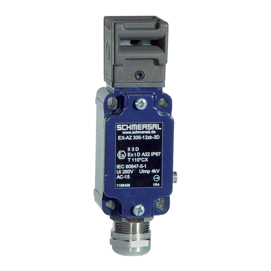
Montage- und Anschlussanleitung / Sicherheitsschalter
Mounting and wiring instructions / Safety Interlock Switch
Instructions de montage et de câblage / Interrupteur de sécurité
Hinweis
deutsch
Der elektrische Anschluss darf nur von autorisiertem Fachpersonal
durchgeführt werden. Die Konformitätserklärung nach Maschinen-
und Niederspannungsrichtlinie senden wir Ihnen auf Wunsch gerne
zu oder kann im Internet abgerufen werden. Weitere technische
Informationen entnehmen Sie bitte dem Schmersal Gesamtkatalog.
Montage
Die Befestigungsmaße sind auf der Rückseite des Gerätes benannt.
Das Schaltergehäuse darf nicht als Anschlag benutzt werden. Die
Gebrauchslage ist beliebig. Sie sollte so gewählt werden, dass kein
grober Schmutz in die benutzte Öffnung eindringen kann. Die nicht
benutzten Öffnungen nach der Montage mit den Schlitzverschlüssen
(AZ 335/355-1990 als Zubehör erhältlich) verschließen. Bitte beachten
Sie auch die Hinweise der Normen EN 292, EN 953 und EN 1088.
Montage der Betätiger: Siehe Montageanleitung Betätiger
Verdrahtung und Abdichtung
Die Kontaktbezeichnungen sind im Schalterinnenraum benannt. Zur
Leitungseinführung sind geeignete Kabelverschraubungen mit
entsprechender Schutzart zu verwenden. Nicht benutzte Einführungs-
öffnungen (AZ 355) mit Gewindestopfen verschließen. Nach erfolgtem
Anschluss ist der Schalterinnenraum von Schmutzteilen zu säubern.
Wartung
Bei rauen Betriebsbedingungen empfehlen wir eine regelmäßige
Wartung mit folgenden Schritten:
1. Prüfen des Betätigers und des Sicherheitsschalters auf festen Sitz
2. Entfernen von Schmutz
3. Prüfen der Leitungseinführung und -anschlüsse
Notice
english
The electrical connection may only be carried out by an authorized
person. The declaration of conformity according to the Machinery and
Low Voltage Directive can be mailed to you on request or can be
drawn from our webside. Further technical information can be found
in the Schmersal Main Catalogue.
Mounting
The mounting dimensions are on the back of the switch. The
switch may not be used as an endstop. The switch is suitable for any
mounting position. It should be selected in such a way, that no coarse
dirt can fall into the used slot. The unused slots should be protected
with the optional slotcaps (AZ 335/355-1990). Please observe the
instructions in the standards EN 292, EN 953 and EN 1088.
Mounting of the actuators: See mounting instructions actuators
Wiring and Sealing
The contact numbers can be found in the wiring compartment. For
cable entries please use suitable cable glands with the appropriate
protection class. Please seal not used entries (AZ 355) with a blind
gland accordingly. Clean the inside of the switch from dirt after
wiring.
Maintenance
With rough conditions, we recommend quarterly maintenance per the
following steps:
1. Check for tight installation of the actuator and the switch
2. Remove all debris or particles
3. Check the sealing of the cable and the conduit connections
Remarque
français
Le raccordement électrique doit être effectué uniquement par du
personnel technique habilité. Une attestation de conformité à la
directive Machines et Basse Tension peut vous être adressée sur
simple demande ou obtenue via Internet.
Montage
Les cotes de fixation des interrupteurs de positions sont indiquées
à l'arrière du boîtier. Ne pas utiliser le boîtier de l'interrupteur comme
butée. La position d'utilisation est indifférente. Toutefois, elle doit
être choisie de manière à empêcher la pénétration de salissures
grossières dans l'orifice utilisé. Les orifices non utilisés doivent être
obturés après montage à l'aide des adhésifs obturateurs (accessoire
AZ 335/355-1990 en vente). Respecter également les directives ou
normes EN 292, EN 953 et EN 1088.
Montage des actionneurs: Voir les instructions de montage des
actionneurs
Câblage et étanchéité
La numérotation des contacts est indiquée dans le boîtier. Pour les
passages de filerie, utiliser des presse-étoupe appropriés avec le
degré de protection correspondant. Obturer les orifices ouverts non
utilisés (AZ 355) au moyen de bouchons à vis. Une fois le câblage
terminé, nettoyer impérativement l'intérieur de l'interrupteur pour éli-
miner les débris.
Entretien
En cas de fonctionnement dans un environnement difficile, il est
recommandé d'effectuer un entretien régulier qui consiste à:
1. Contrôler que l'actionneur et l'interrupteur de sécurité
sont solidement fixés.
2. Eliminer les salissures.
3. Contrôler les entrées de filerie et les raccordements.
LED-Ausführung
GN
LED version
Version à LED
1
3 2
13
AZ 335
AZ 355
L+
YE
13
24 VDC
14
14
L-
3
2
YE
GN
1
Werbung

Verwandte Anleitungen für schmersal AZ 335

Inhaltszusammenfassung für schmersal AZ 335
- Seite 1 à l'aide des adhésifs obturateurs (accessoire (AZ 335/355-1990 als Zubehör erhältlich) verschließen. Bitte beachten AZ 335/355-1990 en vente). Respecter également les directives ou Sie auch die Hinweise der Normen EN 292, EN 953 und EN 1088. normes EN 292, EN 953 et EN 1088.
- Seite 2 Contacts are shown with safety guard closed Short-circuit protection 6 A gL/gG D-fuse Contact représenté avec le protecteur fermé Protection contre les courts circuits 6 A gL/gG D-fussible K. A. Schmersal GmbH Telefon +49 - (0)2 02 - 64 74 - 0 Industrielle Sicherheitsschaltsysteme Telefax +49 - (0)2 02 - 64 74 - 1 00 Möddinghofe 30, D - 42279 Wuppertal...
- Seite 3 Los orificios no utiliza- dos deberán ser tapados mediante las piezas previstas a tal fin (acce- sorio AZ 335/355-1990, en venta). Al mismo tiempo hay que procurar respetar las Directivas o las Normas EN 292, EN 953, y EN 1088.
- Seite 4 Istruzioni di montaggio e collegamento / Interruttore di sicurezza AZ 335 Instrucciones de montaje y cableado / Interruptor de Seguridad AZ 355 Scelta del piano di azionamento Castelletto girevole italiano Per modificare il piano di azionamento svitare le due viti Torx (allo Cabezal giratorio de accionamiento scopo è...