Werbung
Verfügbare Sprachen
Verfügbare Sprachen
Quicklinks
Installationsvejledning
Installation guide
Montageanleitung
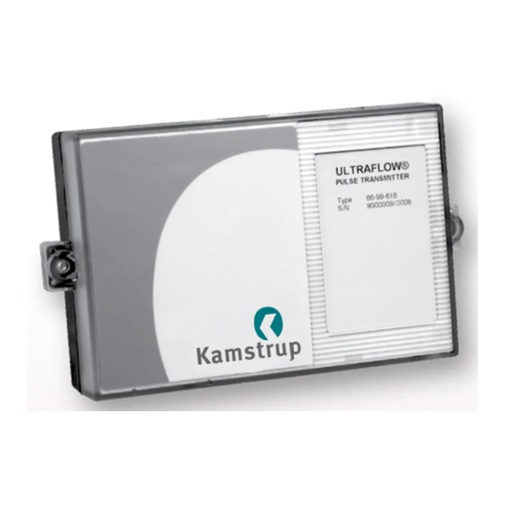
PULSE TRANSMITTER
ULTRAFLOW® 14 & ULTRAFLOW® 24
6699618
Kamstrup A/S · Industrivej 28, Stilling · DK-8660 Skanderborg · T: +45 89 93 10 00 · info@kamstrup.com · kamstrup.com
Werbung

Inhaltszusammenfassung für Kamstrup ULTRAFLOW 24
- Seite 1 Installationsvejledning Installation guide Montageanleitung PULSE TRANSMITTER ULTRAFLOW® 14 & ULTRAFLOW® 24 6699618 Kamstrup A/S · Industrivej 28, Stilling · DK-8660 Skanderborg · T: +45 89 93 10 00 · info@kamstrup.com · kamstrup.com...
- Seite 2 YELLOW – terminal 10 Place the cable in the relief of the base and pull excessive cable out of the case. Mount the reading top. Do not forget to close unused cable entries with the enclosed plugs. Kamstrup A/S • 5512587_C1_GB-DE-DK_10.2016...
- Seite 3 Platzieren Sie das Kabel in die Kabelentlastung des Bodenkastens, und ziehen Sie überschüssiges Kabel aus dem Kasten. Montieren Sie hiernach den Ausleseoberteil. Vergessen Sie nicht, unbenutzte Kabeldurchführungen mit den mitgelieferten Pfropfen zu schließen. Meter Extension base base Blue Black Yellow Label 2004-288 Blue Yellow Kamstrup A/S • 5512587_C1_GB-DE-DK_10.2016...
- Seite 4 Temperature sensors (ULTRAFLOW® 14 only) Extension base Label 2004-288 Meter base 5512587_C1_GB-DE-DK_10.2016...
