hjh OFFICE GENIDIA SMART Aufbauanleitung
Quicklinks
Aufbau
1 Drücken Sie die fünf Stuhlrollen in die Enden
des Fußkreuzes. Stecken Sie die Gasfeder
mittig in das Fußkreuz. Entfernen Sie (falls
vorhanden) vor dem Einbau die Schutzkap-
pe vom Auslösepin der Gasfeder. Diese lässt
sich leicht entfernen.
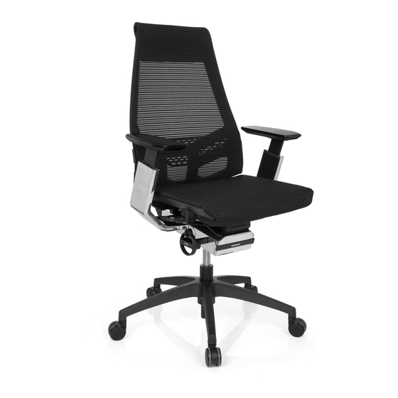
2 Montieren Sie die Armlehnen am Sitzteil wie
im Bild gezeigt. Setzen Sie anschließend das
Sitzteil auf die Gasdruckfeder.
3 Montieren Sie die Rückenlehne am Sitzteil.
4 Setzen Sie sich nun mehrmals auf den Stuhl,
damit die Verbindung zwischen Sitz, Gas-
feder und Fuß gefestigt wird. Anschließend
können Sie die Gasfeder bedienen und die
Stuhlhöhe individuell einstellen.
Sicherheitshinweis Gasfeder:
Gasfeder nie selbst zerlegen, einstechen oder
öffnen. Korpus steht unter Druck.
#
Bezeichnung
Stück
A
Inbusschlüssel
1x
B
Schraube M8x35 (Rückenlehne)
5x
C
Schraube M8x18,5 (Armlehne)
7x
Assembly
1 Insert the five castors into designated holes
at the bottom of the 5-star base. Insert the
gaslift into the center of the base. If present,
remove the plastic protective cap from the
gas lift.
2 Mount the armrests onto the seat and place
the seat onto the gaslift.
3 Mount the back rest onto the seat.
4 Repeatedly sit onto the chair, so that the
connections between the seat, gaslift and
foot tighten. Now you can adjust the chair to
your individual needs.
Caution Gaslift:
Never disassemble, puncture or open Gas spring.
Gas cylinder is under pressure.
#
Part
Count
A
Allen wrench
1x
B
Screw M8x35 (backrest)
5x
C
Screw M8x18,5 (armrest)
7x
GENIDIA SMART
Aufbauanleitung
Assembly instructions
Praktischer Tipp!
So stellen Sie Ihren neuen
Bürostuhl richtig ein!

Verwandte Anleitungen für hjh OFFICE GENIDIA SMART


Inhaltszusammenfassung für hjh OFFICE GENIDIA SMART
- Seite 1 5-star base. Insert the mittig in das Fußkreuz. Entfernen Sie (falls gaslift into the center of the base. If present, GENIDIA SMART vorhanden) vor dem Einbau die Schutzkap- remove the plastic protective cap from the pe vom Auslösepin der Gasfeder.
- Seite 2 Entfernen Sie vor dem Einbau die Schutzkappe vom Auslösepin der Gasfe- der (falls vorhanden). Diese lässt sich leicht entfernen. If present, remove the plastic protective cap from the gas lift. Darstellung kann von tatsächlicher Ausführung abweichen. Siehe Rückseite für weitere Informationen. Illustration may vary from the actual product.