
Verwandte Anleitungen für SAF-HOLLAND TRAK

Inhaltszusammenfassung für SAF-HOLLAND TRAK
- Seite 1 Installationsanleitung TRAK Hydraulisch angetriebene Achse XL-PS40035BM-de-DE Rev H Original Installationsanleitung...
-
Seite 2: Urheberrecht
Diese Installationsanleitung enthält Texte und Zeichnungen, die ohne ausdrückliche Genehmigung des Herstellers weder vollständig noch teilweise • vervielfältigt, • verbreitet oder • anderweitig mitgeteilt werden dürfen. Zuwiderhandlungen verpflichten zu Schadenersatz. XL-PS40035BM-de-DE Rev H · Edition 11/2018 · Änderungen und Irrtümer vorbehalten © SAF-HOLLAND GmbH... -
Seite 3: Inhaltsverzeichnis
3.7 Steckerbelegung 13-Pol ADR / HDSCS (Nr. 24) 3.8 Schaltplan Kippventil mit Druckumschaltung 3.9 Zeichnung Kabelbaum (Nr. 25) 3.10 Zeichnung Ventilblock 3.11 Zeichnung Umschaltventil 3.12 Zeichnung Electronic Control Unit XL-PS40035BM-de-DE Rev H · Edition 11/2018 · Änderungen und Irrtümer vorbehalten © SAF-HOLLAND GmbH... -
Seite 4: Allgemeine Informationen
Dieser Sicherheitshinweis mit dem Signalwort “Gefahr” warnt vor einem möglichen 1.4 Umweltschutz Sicherheitsrisiko oder vor schweren und tödlichen Verletzungen! Alle bei der Wartung und Pflege des Produktes anfallenden Bauteile, Hilfs- und Betriebsstoffe sind XL-PS40035BM-de-DE Rev H · Edition 11/2018 · Änderungen und Irrtümer vorbehalten © SAF-HOLLAND GmbH... -
Seite 5: Kennzeichnung Von Textstellen
• Wird festgestellt, dass Hydrauliköl an Leitungen • Anpassungen und Änderungen am und Hydraulikkomponenten austritt, ist der Lieferumfang der SAF TRAK sind nicht Nebenantrieb sofort abzustellen und eine zulässig. Fachwerkstatt aufzusuchen. XL-PS40035BM-de-DE Rev H · Edition 11/2018 · Änderungen und Irrtümer vorbehalten © SAF-HOLLAND GmbH... - Seite 6 Alle Hydrauliköle z.B. Klasse 32 oder 46. ● Neues Hydrauliköl kann verunreinigt sein. Das Hydrauliksystem muss deshalb immer über einen Einfüllfilter mit einer entsprechenden Filtereinheit, wie auf dem jeweiligen Datenblatt des Ventilblocks angegeben, befüllt werden. XL-PS40035BM-de-DE Rev H · Edition 11/2018 · Änderungen und Irrtümer vorbehalten © SAF-HOLLAND GmbH...
-
Seite 7: Funktions- Und Schaltpläne
Installationsanleitung 3. Funktions- und Schaltpläne 3.1 Elektrischer Schaltplan XL-PS40035BM-de-DE Rev H · Edition 11/2018 · Änderungen und Irrtümer vorbehalten © SAF-HOLLAND GmbH... -
Seite 8: Hydraulischer Schaltplan
Installationsanleitung 3.2 Hydraulischer Schaltplan XL-PS40035BM-de-DE Rev H · Edition 11/2018 · Änderungen und Irrtümer vorbehalten © SAF-HOLLAND GmbH... -
Seite 9: Hydraulischer Anschluss
Installationsanleitung 3.3 Hydraulischer Anschluss XL-PS40035BM-de-DE Rev H · Edition 11/2018 · Änderungen und Irrtümer vorbehalten © SAF-HOLLAND GmbH... -
Seite 10: Pneumatischer Schaltplan
Installationsanleitung 3.4 Pneumatischer Schaltplan XL-PS40035BM-de-DE Rev H · Edition 11/2018 · Änderungen und Irrtümer vorbehalten © SAF-HOLLAND GmbH... -
Seite 11: Aufbau Fahrzeug
Installationsanleitung 3.5 Aufbau Fahrzeug Vorsicht! • Die Hydraulikzuleitung (rot) zum Hydraulikmotor erfordert einen Innendurchmesser (DN) ≥20mm ab dem Ventilblock. • Die Rückleitung (blau) vom Hydraulikmotor erfordert einen Innendurchmesser (DN) ≥25mm ab dem Ventilblock. XL-PS40035BM-de-DE Rev H · Edition 11/2018 · Änderungen und Irrtümer vorbehalten © SAF-HOLLAND GmbH... -
Seite 12: Elektrischer Anschluss
Installationsanleitung 3.6 Elektrischer Anschluss XL-PS40035BM-de-DE Rev H · Edition 11/2018 · Änderungen und Irrtümer vorbehalten © SAF-HOLLAND GmbH... -
Seite 13: Steckerbelegung 13-Pol Adr / Hdscs (Nr. 24)
Installationsanleitung 3.7 Steckerbelegung 13-Pol ADR / HDSCS (Nr. 24) XL-PS40035BM-de-DE Rev H · Edition 11/2018 · Änderungen und Irrtümer vorbehalten © SAF-HOLLAND GmbH... -
Seite 14: Schaltplan Kippventil Mit Druckumschaltung
Installationsanleitung 3.8 Schaltplan Kippventil mit Druckumschaltung XL-PS40035BM-de-DE Rev H · Edition 11/2018 · Änderungen und Irrtümer vorbehalten © SAF-HOLLAND GmbH... - Seite 15 Installationsanleitung XL-PS40035BM-de-DE Rev H · Edition 11/2018 · Änderungen und Irrtümer vorbehalten © SAF-HOLLAND GmbH...
- Seite 16 Installationsanleitung XL-PS40035BM-de-DE Rev H · Edition 11/2018 · Änderungen und Irrtümer vorbehalten © SAF-HOLLAND GmbH...
-
Seite 17: Zeichnung Kabelbaum (Nr. 25)
Installationsanleitung 3.9 Zeichnung Kabelbaum (Nr. 25) XL-PS40035BM-de-DE Rev H · Edition 11/2018 · Änderungen und Irrtümer vorbehalten © SAF-HOLLAND GmbH... -
Seite 18: Zeichnung Ventilblock
Installationsanleitung 3.10 Zeichnung Ventilblock XL-PS40035BM-de-DE Rev H · Edition 11/2018 · Änderungen und Irrtümer vorbehalten © SAF-HOLLAND GmbH... -
Seite 19: Zeichnung Umschaltventil
Installationsanleitung 3.11 Zeichnung Umschaltventil XL-PS40035BM-de-DE Rev H · Edition 11/2018 · Änderungen und Irrtümer vorbehalten © SAF-HOLLAND GmbH... -
Seite 20: Zeichnung Electronic Control Unit
Installationsanleitung 3.12 Zeichnung Electronic Control Unit XL-PS40035BM-de-DE Rev H · Edition 11/2018 · Änderungen und Irrtümer vorbehalten © SAF-HOLLAND GmbH... - Seite 21 Installationsanleitung Notizen XL-PS40035BM-de-DE Rev H · Edition 11/2018 · Änderungen und Irrtümer vorbehalten © SAF-HOLLAND GmbH...
-
Seite 22: Kontaktinformation
Kontaktinformation Notruf +49 6095 301-247 Kundendienst / Service Telefon +49 6095 301-602 +49 6095 301-259 E-Mail service@safholland.de Aftermarket / Ersatzteile Telefon +49 6095 301-301 +49 6095 301-494 E-Mail originalparts@safholland.de www.safholland.com SAF-HOLLAND GmbH Hauptstraße 26 D-63856 Bessenbach... - Seite 23 System Components SAF TRAK Page 1 TRAK_sys_comp_v01_r11.doc Doc: SAF TRAK System Components Overview of all system components necessary for the SAF TRAK starting aid, subsequent named TRAK Date: 12-November-2018...
- Seite 24 System Components SAF TRAK Page 2 TRAK_sys_comp_v01_r11.doc Doc: Content System Components Scheme ...................... 6 Axle .......................... 8 Pneumatic components ......................9 Hydraulic Components ......................9 Hydraulic Components, Poclain (drawing available) ..................12 Wiring harness Truck ......................17 Wiring harness Trailer ......................18 Coiled cable ........................
- Seite 25 System Components SAF TRAK Page 3 TRAK_sys_comp_v01_r11.doc Doc: Date: 12-November-2018...
- Seite 26 System Components SAF TRAK Page 4 TRAK_sys_comp_v01_r11.doc Doc: Figure 1: System Components ...................... 6 Figure 2: Selector Valve – No. 28, 04 425 0158 00 ..................13 Figure 3: Block Assist – No. 29, 04 425 0159 00 ..................14 Figure 4: Hydraulic Motor –...
- Seite 27 System Components SAF TRAK Page 5 TRAK_sys_comp_v01_r11.doc Doc: Date: 12-November-2018...
-
Seite 28: System Components Scheme
System Components SAF TRAK Page 6 TRAK_sys_comp_v01_r11.doc Doc: System Components Scheme Figure 1: System Components Date: 12-November-2018... - Seite 29 System Components SAF TRAK Page 7 TRAK_sys_comp_v01_r11.doc Doc: Table 1: Components Component page Component page Assist Switch 23/34 23/22 Status Lamp 23/33 Air Reservoir (Trailer) Error Lamp 23/33 Axle Air Valve 23/22 Hydraulic Motor Right Exchange Valve, OR Hydraulic Motor Left...
-
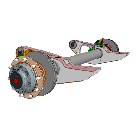
Seite 30: Axle
System Components SAF TRAK Page 8 TRAK_sys_comp_v01_r11.doc Doc: Axle Table 2: Description of the Axle, No.33 Component Type Definition Axle Axle version BIM9 B: Offset 120mm I: Integral brake disc M: Motor 9: permitted axle load 9t Axle tube Outer-Ø x thickness: 146mm x 14mm Axle stubs Drawing number: 06 002 1693 00 –... -
Seite 31: Pneumatic Components
System Components SAF TRAK Page 9 TRAK_sys_comp_v01_r11.doc Doc: Pneumatic components Table 3: Overview pneumatic components Component Type Definition Exchange valve, OR pneumatic Ports for: pneumatic hoses 8x1 Nominal Inner Diameter: ≥3mm Pneumatic Tip Control No special requirements related to the TRAK... - Seite 32 System Components SAF TRAK Page 10 TRAK_sys_comp_v01_r11.doc Doc: Tipping Valve Two-stage (low & high Manufacturer specifications shall be observed. pressure stage) In addition: Max. Pressure (Low pressure stage): depending on the connected tipping cylinder Max. pressure (High pressure stage): 350bar...
- Seite 33 System Components SAF TRAK Page 11 TRAK_sys_comp_v01_r11.doc Doc: High pressure hydraulic Working Pressure 350 Bar components (Trailer) Oil Temperature range -40 °C to +100 °C Minimum internal diameter ≥ 20mm Hydraulic Tubes Right Hydraulic Tubes Left Suction Line – Hydraulic Pump Ø...
-
Seite 34: Hydraulic Components, Poclain (Drawing Available)
System Components SAF TRAK Page 12 TRAK_sys_comp_v01_r11.doc Doc: Hydraulic Components, Poclain (drawing available) Table 5: Overview hydraulic components, Poclain Component Type Definition Selector Valve Drawing number: 04 425 0158 00 Block Assist Drawing number: 04 425 0159 00 Hydraulic Motor, right Drawing number: 91 422 6391 00 –... - Seite 35 System Components SAF TRAK Page 13 TRAK_sys_comp_v01_r11.doc Doc: Figure 2: Selector Valve – No. 28, 04 425 0158 00 Date: 12-November-2018...
- Seite 36 System Components SAF TRAK Page 14 TRAK_sys_comp_v01_r11.doc Doc: Figure 3: Block Assist – No. 29, 04 425 0159 00 Date: 12-November-2018...
- Seite 37 System Components SAF TRAK Page 15 TRAK_sys_comp_v01_r11.doc Doc: Figure 4: Hydraulic Motor – No. 34&35, 91 422 6391 00 – S01 Date: 12-November-2018...
- Seite 38 System Components SAF TRAK Page 16 TRAK_sys_comp_v01_r11.doc Doc: Figure 5: Hydraulic Motor – No. 34&35, 91 422 6391 00 – S02 Date: 12-November-2018...
-
Seite 39: Wiring Harness Truck
System Components SAF TRAK Page 17 TRAK_sys_comp_v01_r11.doc Doc: Wiring harness Truck The “Wiring harness Truck” shall connect the components Table 6 with the Trailer via the Connector component No.42. The “Wiring harness Truck” have to fulfill the chapter “SAF General wiring requirements”. -
Seite 40: Wiring Harness Trailer
System Components SAF TRAK Page 18 TRAK_sys_comp_v01_r11.doc Doc: Wiring harness Trailer Table 7: Component No. 24. Connectors No.45/46 Connectors on Wiring harness Component No.45 Component No.46 Trailer 13 Pole ADR HDSCS TYCO Cable length 8.0m +/- 100mm Connector referring Connector... - Seite 41 System Components SAF TRAK Page 19 TRAK_sys_comp_v01_r11.doc Doc: Figure 6: Drawing Cable 13-pole to HDSCS,No.24; 04 424 2041 00 Date: 12-November-2018...
-
Seite 42: Coiled Cable
System Components SAF TRAK Page 20 TRAK_sys_comp_v01_r11.doc Doc: Coiled cable Table 8: Component No.21 Connectors No.43/44 Component No.21 Component No.43 Component No.44 Cable E1 Coiled Cable Plug A Coiled Cable Plug B Cable length 4.0m +/- 13P-ADR-Plug 13P-ADR-Plug referring to... - Seite 43 System Components SAF TRAK Page 21 TRAK_sys_comp_v01_r11.doc Doc: Figure 7: Drawing Cable Selector Valve No. 26; 04 424 2040 00 Date: 12-November-2018...
-
Seite 44: Saf General Wiring Requirements
System Components SAF TRAK Page 22 TRAK_sys_comp_v01_r11.doc Doc: SAF General wiring requirements Table 10: Harness requirements Harness requirements connecting cable shall meet the requirements of the applicable parts of ISO 4141 The CAN bus must be wired using shielded or unshielded twisted pair. CAN bus must be wired according to SAE J1939-11 or SAE J1939-15. - Seite 45 System Components SAF TRAK Page 23 TRAK_sys_comp_v01_r11.doc Doc: Figure 9: Wiring-Diagram Date: 12-November-2018...
-
Seite 46: Ecu
System Components SAF TRAK Page 24 TRAK_sys_comp_v01_r11.doc Doc: Figure 10: ECU – 03 425 0162 00 Date: 12-November-2018... -
Seite 47: Wiring Harness Ecu
System Components SAF TRAK Page 25 TRAK_sys_comp_v01_r11.doc Doc: Wiring harness ECU Figure 11: Wiring Harness ECU – 04 424 2039 00 Date: 12-November-2018... -
Seite 48: Connectors
System Components SAF TRAK Page 26 TRAK_sys_comp_v01_r11.doc Doc: Connectors Figure 12: DIN72585 Connectors(left) and HDSCS Connectors(right) Date: 12-November-2018... -
Seite 49: Can Signals
System Components SAF TRAK Page 27 TRAK_sys_comp_v01_r11.doc Doc: Can signals The following CAN signals shall be available. Application layer acc. SAE J1939 Physical layer acc. ISO 11898 High-Speed-CAN/5V Base/250 kBaud Table 12: J1939 CAN-Messages Name Identifier Freq Byte Bit Comment / Parameter... - Seite 50 System Components SAF TRAK Page 28 TRAK_sys_comp_v01_r11.doc Doc: Clutch Switch 2 bits 0 to 3 ETC2 xx F0 05 xx Transmission selected gear (only 1 / off: - -125 to 125 automatic gear box) (P=xx if signal is missing or if signal data > 0xFB => detection of error...
-
Seite 51: Truck Dependent Can Message To Get Gear Box Direction
System Components SAF TRAK Page 29 TRAK_sys_comp_v01_r11.doc Doc: Truck dependent CAN message to get gear box direction Scania Table 13: CAN-Scania Name Identifier Freq Byte Bit Comment / Parameter SPN Length or Operating Data range resolution (Hex) BCI1 xx FF 28 xx... -
Seite 52: Daf
System Components SAF TRAK Page 30 TRAK_sys_comp_v01_r11.doc Doc: Table 15: CAN-DAF Name Identifier Freq Byte Bit Comment / Parameter SPN Length or Operating Data range resolution (Hex) TCO1 xx FE 6C xx 7-8 Direction indicator 2bits : Forward : Reverse... -
Seite 53: Application Layer Acc. Iso 11992-3 Physical Layer Acc. Iso 11898 High-Speed-Can/5V Base/250 Kbaud
System Components SAF TRAK Page 31 TRAK_sys_comp_v01_r11.doc Doc: Application layer acc. ISO 11992-3 Physical layer acc. ISO 11898 High-Speed-CAN/5V Base/250 kBaud GPM 13 (Transmission rate: 50 ms): Table 16: CAN-Daimler GPM 13 Name Identifier Byte Bit Comment / Parameter Length or... - Seite 54 System Components SAF TRAK Page 32 TRAK_sys_comp_v01_r11.doc Doc: GPM 14 (Transmission rate: 100 ms): Table 17: CAN-Daimler GPM 14 Name Identifier Byte Bit Comment / Parameter Length or Operating Data range resolution (Hex) GPM 14 xx FE 61 xx 65121...
-
Seite 55: Human Interface
Rated voltage Maximal current consumption 400 mA Identifikation shall be clearly identified as SAF TRAK Status and Error Lamp General The light-signaling shall meet the requirements of the applicable parts of ECE 121 Regulation Location From the driver’s seat, in the cabin, the lamps shall be directly visible. -
Seite 56: Assist Switch
-40°C ≤…≤ +80°C Endurance ≥40000 Lock function Switch with lock Identifikation shall be clearly identified as SAF TRAK Switch and background illuminated switched with the low beam light Voltage Rating Current Rating ≥10A Location From the driver’s seat, in the cabin, the Assist Switch shall be reached easily by the operator. -
Seite 57: Change History
System Components SAF TRAK Page 35 TRAK_sys_comp_v01_r11.doc Doc: Change history Table 21: Change-history Document Name / date Chapter Changes version Rev. 00 Simon Wiring harness Trailer Initialversion Schäfers / Coiled cable 11.04.2018 Wiring harness Selector Valve General wiring requirements Air Valve... - Seite 58 System Components SAF TRAK Page 36 TRAK_sys_comp_v01_r11.doc Doc: Document Name / date Chapter Changes version Page 9-10 Definition of a range for pressure and volume flow for the components 9, 11, 16, 17, 18, 19, 22, 23, 36, 37, 40, 41...