HELIX U 8A Bedienungsanleitung
Inhaltsverzeichnis
Verfügbare Sprachen
Verfügbare Sprachen
Inhaltsverzeichnis

Verwandte Anleitungen für HELIX U 8A


Inhaltszusammenfassung für HELIX U 8A
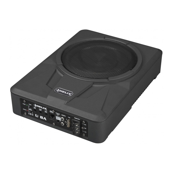
- Seite 1 U 8A / U 10A Ultrakompakter 200 / 250 mm Aktiv-Subwoofer Ultra-compact 8 / 10” active subwoofer...
-
Seite 2: Allgemeine Hinweise
6. Die Qualität und Sorgfalt des Einbaus hat ent- Plus und Minus zu Minus. scheidenden Einfluss auf den Klang des Aktiv- 4. Im Sinne der Unfallsicherheit muss der Subwoofers. Bitte führen Sie jeden Schritt mit U 8A / U 10A professionell montiert werden. größtmöglicher Sorgfalt durch. - Seite 3 Bei anderen Systemen können der HELIX Die Kabelverbindungen müssen so verlegt sein, dass keine Klemm-, Quetsch- oder Bruchgefahr be- U 8A / U 10A und die elektrische Anlage des Kfz beschädigt werden. Die Plusleitung für die gesamte steht. Bei scharfen Kanten (Blechdurchführungen) Anlage sollte in einem Abstand von max.
-
Seite 4: Anschluss- Und Bedienelemente
Anschluss- und Bedienelemente Power & Protect LEDs Remote Control Die Power & Protect LEDs zeigen den Eingang zum Anschluss der mitgelieferten Betriebszustand des Aktiv-Subwoofers an. Fernbedienung zur Lautstärkeregelung. Phase Highlevel Input Schalter zur Umschaltung der Phase zwi- Hochpegel-Lautsprechereingang zum An- schen 0°... -
Seite 5: Input Level
Einstellung von 100 Hz (Mittelstellung des funktion des Aktiv-Subwoofers. Diese Fehlfunkti- Reglers). on kann unterschiedliche Ursachen haben, da der U 8A / U 10A mit verschiedenen elektronischen Schutzschaltungen ausgestattet ist. Diese schal- ten den Aktiv-Subwoofer bei Überhitzung, Über- und Unterspannung und Fehlanschluss ab. Prüfen Sie in diesem Fall alle Anschlüsse auf Fehler, wie... - Seite 6 Inbetriebnahme und Funktionen 8 Highlevel Input Power Input 2-Kanal Hochpegel-Lautsprechereingang. Mit Hilfe Diese Kontakte dienen zum Anschluss der Span- dieses Eingangs kann der Aktiv-Subwoofer direkt nungsversorung und der Remote-Leitung. an die Lautsprecherausgänge eines Werks- / Nach- +12 V: Das +12 V Versorgungskabel ist am Pluspol rüstradios angeschlossen werden, sofern dieses der Batterie anzuschließen.
-
Seite 7: Einbau Und Installation
Einbau und Installation Option 1: Anschluss des Aktiv-Subwoofers bei Verwendung der Highlevel-Eingänge Masse Masse Sicherung optional: Remote-Leitung Kabelfernbe- Max. Abstand zur dienung Spannungsquelle: 30 cm Spannungsquelle Hinweis: Bei Verwendung der Highlevel-Eingänge als Signaleingang schaltet der Aktiv-Subwoofer automatisch ein, so dass der Remote-Eingang nicht belegt werden muss. Stellen Sie dazu den Auto Remote-Schalter auf „On“. Sollte es zu Störgeräuschen beim Ein- und Ausschalten kommen, verwenden Sie bitte den Remote-Eingang und stellen den Auto Remote-Schalter auf „Off“. - Seite 8 Der Wert der Sicherung errechnet sich aus Kanal L = Links vorne der maximalen Stromaufnahme der gesamten Car-Hifi Anlage (U 8A / U 10A = max. 25 A RMS Kanal R = Rechts vorne bei 12 V Bordnetz). Verwenden Sie bei kurzen...
- Seite 9 6. Konfiguration des Remote-Eingangs Hinweis: Wird die automatische Einschaltung Die Einschaltung des U 8A / U 10A erfolgt des U 8A / U 10A deaktiviert, muss der Remo- automatisch bei Ansteuerung über die Hoch- te-Eingang belegt werden. Eine automatische pegel-Lautsprechereingänge oder sobald ein Einschaltung über den Hochpegel-Lautspre-...
-
Seite 10: Technische Daten
Technische Daten U 8A U 10A Leistung RMS / Max. 180 / 360 Watt 180 / 360 Watt Durchmesser Tieftöner 200 mm 250 mm Eingänge 2 x Cinch 2 x Cinch 2 x Hochpegel-Lautsprecherein- 2 x Hochpegel-Lautsprecherein- gang gang 1 x Remote In... - Seite 20 Audiotec Fischer GmbH Hünegräben 26 · 57392 Schmallenberg · Germany Tel.: +49 2972 9788 0 · Fax: +49 2972 9788 88 E-mail: helix@audiotec-fischer.com · Internet: www.audiotec-fischer.com...