Neutec sonnEC 1 Anleitung
Axialventilator

Inhaltszusammenfassung für Neutec sonnEC 1
- Seite 1 1 · sonnEC 2 · sonnEC 3 · sonnEC 4 · sonnEC 0 TECHNISCHE DOKUMENTATION TECHNICAL DOCUMENTATION...
-
Seite 3: Inhaltsverzeichnis
AND CONDITIONS FOR THE SonnEC PRODUCTS GARANTIEBEDINGUNGEN FÜR SonnEC PRODUKTE 11. ELECTRIC DIAGRAMS 11.1. Connection of sonnEC 1, 2, 3, 4, 0 with EC motor to the HMI sonnEC 11. ELEKTRISCHE SCHALTPLÄNE 11.1. Anschluss von sonnEC 1, 2, 3, 4, 0 mit einem 11.2. -
Seite 4: Einleitung
Temperaturgradienten in den Luftschichten und trägt zur Reduzierung der Heizkosten des Objektes durch Senkung der Temperatur im Deckenbereich und Einschränkung der Wärmeverluste über das Dach bei. Der Destratifkator sonnEC 0 wird sich in Verbindung mit den Lufterhitzern sonnEC 1, 2, 3 oraz 4 ausgezeichnet bewähren. Im Hinblick auf die Unterstützung des... -
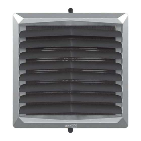
Seite 5: Aufbau Des Gerätes
Alu-Lamellen. Die Anschlusskollektoren (Außengewinde ¾“) sind im hinteren Bereich des Gehäuses angeordnet. Unsere Typenreihe beinhaltet bei sonnEC 2 5-30k die Anwendung eines Einreihen-Wärmetauschers, bei sonnEC 1 3-20kW, sonnEC 3 8-50kW die Anwendung von Zweireihen-Wärmetauschern und bei sonnEC 4 13-75kW die Anwendung von Dreireihen-Wärmetauschern. -
Seite 6: Technische Daten
– Wassertemperatur im Rücklauf; T – Lufttemperatur am Einlass; T – Lufttemperatur am Auslass; P – Heizleistung des Gerätes; – Wasserdurchfluss; Q - Luftdurchsatz; Δp – Druckabfall am Wärmetauscher sonnEC 1 Parameter T [°C] 90/70 [°C] 80/60 [°C] 70/50 [°C] 50/30 [°C]... - Seite 7 – Wassertemperatur in der Versorgung; T – Wassertemperatur im Rücklauf; T – Lufttemperatur am Einlass; T – Lufttemperatur am Auslass; P – Heizleistung des Gerätes; – Wasserdurchfluss; Q - Luftdurchsatz; Δp – Druckabfall am Wärmetauscher sonnEC 3 Parameter T [°C] 90/70 [°C] 80/60 [°C] 70/50 [°C]...
- Seite 8 Parameter Messeinheit sonnEC 1 sonnEC 2 sonnEC 3 sonnEC 4 sonnEC 0 Anzahl der Reihen innerhalb eines Erwärmers Maximaler Luftdurchsatz m³/h 2100 5300 4850 5700 6500 Heizleistungsbereich 3-20 5-30 8-50 13-75 Maximaltemperatur des Heizmediums °C...
- Seite 9 1 Ventilatorlauf Ventilatordurchsatz m³/h 2100 1650 1100 Lärmpegel für Erwärmer mit EC-Motoren* dB(A) EC Motor Elektrische Leistung** Horizontale Reichweite Vertikale Reichweite * Referenzbedingungen: Volumen des Raumes 1500 m³, die Messung erfolgt in einer Entfernung von 5 m ** Elektrische Leistung des EC-Motors für die vorgenannten Ventilator-Durchsätze...
-
Seite 10: Montage
Montagehöhe * für vertikale Einstellung der Luftleitlamellen Abstand zwischen Geräten – empfohlener Abstand von 6 bis 12 m (sonnEC 2, 3, 4), 3-7 m (sonnEC 1), für die Gewährleistung einer gleichmäßigen Verteilung warmer Luft . 3 - 7 O P T... -
Seite 11: Montage Mit Konsole
Beispiele für eine Anordnung der Lufterhitzer bei einer Wandmontage Draufsicht 4.1. MONTAGE MIT EXEMPLARISCHER KONSOLE Die Montagekonsole ist optional erhältlich. Um die Montagekonsole an dem Gerät zu befestigen, sind in der oberen und unteren Platte des Gerätes Öffnungen mit einem Kronenbohrer auszuschneiden (an gekennzeichneter Stelle 6), und dann Muffen in diese Buchsen einzuführen. -
Seite 12: Hinweise Zur Montage Und Installation
Die Last der geführten Rohrleitung sollte die Anschlüsse des Erhitzers nicht belasten. Es besteht die Möglichkeit, die Rohrleitung über elastische Anschlüsse anzuschließen (flexible Blasrichtung des Gerätes). Volcano VR1, VR2, VR3 sonnEC 1, 2, 3, 4 sonnEC 1 sonnEC 2, 3, 4, 0 return Rücklauf... - Seite 13 Empfohlene Sicherung: Überlastabsicherung (Wassererwärmer sonnEC 1 – 1 A, sonnEC 2, 3 – 2 A, sonnEC 4, 0 - 4A) und FI-Schalter. sonnEC 1, 2, 3, 4, 0 (Gebläse) ist mit einer Klemmleiste ausgerüstet, an die die elektrischen Leitungen 7 x 2,5 mm2 angeklemmt werden können.
-
Seite 14: Automatik
sonnEC sonnEC sonnEC sonnEC sonnEC 5. AUTOMATIK 5.1. AUTOMATIKBESTANDTEILE Elektrische Verbindungen dürfen nur von entsprechend befugtem Elektrofachpersonal gemäß geltenden Arbeitssicherheitsvorschriften, Montageanleitungen, und der technischen Dokumentation pro Automatikbestandteil ausgeführt werden. HINWEIS: Vor Beginn der Montage und dem Anschließen des Systems ist Kenntnis über die Automatikbestandteilen und deren, im Original beigelegten, Dokumentationen erforderlich. MODELL SCHEMA TECHNISCHE DATEN... -
Seite 15: Arbeitssicherheitsanweisung
2 / sonnEC 3 sonnEC 4 28.5% 27.5% 28.0% Ganz VSD-Nein 2017 NEUTEC GmbH, Berlin, Alexanderplatz, Gontardstraße 11, 10178, Deutschland 1-2-2701-0327 1-2-2701-0268 1-2-2701-0262 0,41 kW, 2826 m³/h, 145 Pa 0,48 kW, 4239 m³/h, 124 Pa 0,68 kW, 6006 m³/h, 128 Pa 1376 UpM... -
Seite 16: Service
Eindringen schädlicher Substanzen in die Atmosphäre und Oberflächengewässer. 9.2. REKLAMATIONSVERFAHREN 1. E-mail: neutec@neutec.com.de 2. Internetseite: www.neutec.com.de Unsere Serviceabteilung wird unverzüglich Kontakt zu Ihnen aufnehmen. Für den Fall von Transportschäden ist eine Reklamationsmeldung samt Lieferdokumentation (Frachtbrief, Lieferschein) und Fotos zum Nachweis der Beschädigung einzusenden. WICHTIG! Das Reklamationsverfahren wird mit Erhalt einer ordnungsgemäß... -
Seite 17: Ersatzteileliste
Ansprechpartner: Vorname und Name: Kontakttelefon: E- Mail: * Pflichtfeld, auszufüllen im Falle einer Reklamationsmeldung für Geräte: Lufterhitzer S1, S2, S3, S4, S0 9.3. ERSATZTEILELISTE Pos. Teil sonnEC 1 sonnEC 2 sonnEC 3 sonnEC 4 sonnEC 0 EC-Ventilator 1-2-2701-0327 1-2-2701-0325 1-2-2701-0325... -
Seite 18: Neutec Gmbh Standard-Garantiebedingungen Für Sonnec Produkte
§ 2 Garantieumfang 1. Für den Fall, dass eine Reklamation als begründet erachtet wird, wird NEUTEC nach eigenem Ermessen die Geräte oder deren mangelhafte Teile umtauschen oder diese am Einbauort oder an einem anderen Ort, nach dem Zurücksenden zur Reparatur, reparieren. -
Seite 19: Elektrische Schaltpläne
2 - Hauptschalter, Sicherungen* 4 - sonnEC -Lüfter 9 - Steuerungs-HMI sonnEC 11.2. Anschluss von sonnEC 1, 2, 3, 4 mit einem EC-Motor, dem Steuerungs-HMI sonnEC und einem Ventil-Stellmotor 1 - Versorgung 230V - 50Hz* 2 - Hauptschalter, Sicherungen* 4 - sonnEC -Lüfter... -
Seite 20: Anschluss Von Sonnec 1, 2, 3, 4 Mit Einem Ec-Motor, Dem Steuerungs-Hmi Sonnec, Einem Ventil-Stellmotor Und Einem Temperaturfühler
11.3. Anschluss von sonnEC 1, 2, 3, 4 mit einem EC-Motor, dem Steuerungs-HMI sonnEC, einem Ventil-Stellmotor und einem Temperaturfühler 1 - Versorgung 230V - 50Hz* 2 - Hauptschalter, Sicherungen* 4 - sonnEC -Ventilator 5 - Ventil mit Stellmotor 9 - Steuerungs-HMI sonnEC 10 - externer Temperaturfühler NTC... -
Seite 21: Anschluss Von Sonnec 1, 2, 3, 4, 0 Mit Einem
11.5. Anschluss von sonnEC 1, 2, 3, 4, 0 mit einem EC-Motor und dem Drehzahlregler 0-10 V 1 - Versorgung 230V - 50Hz* 2 - Hauptschalter, Sicherungen* 4 - sonnEC -Ventilator 11 - Drehzahlregler 0-10V *Das Gerät beinhaltet nicht: Hauptschalter des Gerätes, Sicherungen und Stromkabel NEUTEC GmbH www.neutec.com.de... - Seite 40 NEUTEC GmbH Berlin, Alexanderplatz 4th floor, Gontardstraße 11 Berlin 10178, Deutschland...