Alre ITR 79 Bedienungsanleitung
ITR 79
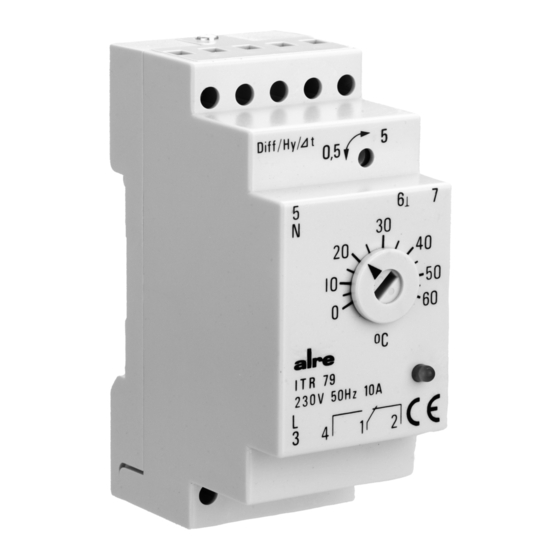
Temperature control device apt for fastening on standard rail
Thermorégulateur électronique pour fixation sur rail standardisé
Regolatore di temperatura per montaggio su guida standardizzata
Achtung!
Dieses Gerät darf nur durch einen Elektrofachmann geöffnet und
gemäß dem entsprechenden Schaltbild im Gehäusedeckel / in der
Bedienungsanleitung installiert werden. Dabei sind die bestehenden
Sicherheitsvorschriften zu beachten.
1. Anwendung
Dieser elektronische 2-Punkt-Regler ist einsetzbar zur Begrenzung
(Wächterfunktion) oder Regelung von Heiz- oder Kühlanlagen.
2. Funktion
Die Typenreihe ITR 79.4xx ist für Heizanlagen und die Typenreihe ITR
79.8xx speziell für Fußbodenheizungen vorgesehen. Sie schalten bei
Unterschreitung der Solltemperatur das Relais ein. Signalisiert wird
der Einschaltzustand durch eine rote LED. Die Typenreihe ITR 79.5xx
ist für Kühlanlagen konzipiert und schaltet bei Überschreitung der Soll-
temperatur das Relais ein. Eine grüne LED signalisiert den Einschalt-
zustand. Bei Ausfall der Versorgungsspannung sowie bei Fühlerbruch
oder -schluss wird das Relais abgeschaltet.
3. Technische Daten
Nennspannung:
230 V, 50/60 Hz
andere Werte siehe Geräteaufdruck
Leistungsaufnahme:
ca. 2,8 VA
Fühler:
externer Fühler NTC
Fühlertoleranz:
± 1 K
Schaltdifferenz:
justierbar 0,5 ... 5 K
Kontakte:
Umschalter potentialfrei
Arbeitskontakt:
max.10(3)A 250 V
Ruhekontakt:
max. 5(1,5)A 250 V
Anzeigen:
LED für Relais ein
elektr. Anschlüsse:
Schraubanschlüsse
pro Klemmstelle:
0,25 mm
Montageart:
Schaltschrankeinbau,
35 mm Tragschiene
Schutzklasse:
II nach entsprechender Montage
Schutzart:
IP 20
Umgebungstemperatur:
–10 ... +50º C
Lagertemperatur:
–20 ... +60ºC
4. Einbaubedingungen
Ein Austausch der Fühler ist ohne Abgleich möglich. Die Austausch-
barkeit der Fühler muss in jeder Einbauvariante gewährleistet sein.
Zum Beispiel muss bei Fußbodenreglern der Fühler im Bereich des
Estrichs und Mauerwerks im Schutzrohr verlegt werden. Die Parallel-
verlegung mit netzspannungsführenden Leitungen ist wegen eventuel-
ler Störeinflüsse zu vermeiden. Eine Verlängerung bis 50 m kann mit
einem Kabel Ø 0,75 ... 1,5 mm
Entfernungen und in der Nähe von Starkstromleitungen ist eine abge-
schirmte Leitung zu verwenden, wobei der Schirm an die Klemme „6"
anzuschließen ist. Das andere Ende des Schirms bleibt unverdrahtet.
Temperaturregler mit Normschienenbefestigung
2
... 2,5 mm
2
2
erfolgen. Bei Überbrückung größerer
Caution!
D
This device must not be opened by any person other than an expert el-
ectrician only and be installed according to the connection diagram
shown in the housing cover / operating instructions. When doing so, all
pertinent safety regulations currently operative and in force must be
complied with and adhered to.
1. Application
This electronic on-off controller can be applied for limitation purposes
(guard function) or for the control of heating or cooling systems.
2. Function
The ITR 79.4xx type series has been especially designed for applica-
tion with heating systems, whereas the ITR 79.8xx type series has
been provided for use with floor heating systems. The control devices
of these series activate the addressed relays if the temperature falls
below the related set temperature value. The related turn on state is
signalled by a red LED. The ITR 79.5xx type series, by contrast, has
been specifically designed for application with cooling devices and
activates the corresponding relays if the temperature passes over the
related set temperature value. The turn-on state is signalled by a
green LED. The relays are deactivated if a power failure, a sensor
breakdown or a sensor short circuit occurs.
3. Technical data
Nominal voltage:
Power input:
Sensor:
Sensor tolerance:
Switching difference:
Contacts:
Make contact:
Break contact:
Visual indications:
Electrical connection:
Type of installation:
Protection class:
System of protection:
Ambient temperature:
Storage temperature:
4. Installation conditions
The sensors can be replaced without adjustment. The interchangeability
of the sensors must be ensured with respect to any possible installation
variant. With floor heating thermostats for example, the sensor, housed
in a protective tube, must be installed in the floor pavement or brick-
work area. To prevent the occurrence of disturbing influences, the parallel
laying of sensor lines and mains supply cables must be avoided. Ex-
tensions of up to 50 m can be realized when using a Ø 0.75 ... 1.5 mm
cable. A shielded sensor line must be used to cover bigger distances.
Same also applies in the event the line is being laid near to powers
lines. In any such case, the shielding must be connected to terminal "6".
The other end of the shielding remains unwired.
230 V, 50/60 Hz, as for other values,
see imprint on the device
approx. 2,8 VA
external NTC sensor
± 1 K
0.5 ... 5 K, adjustable
change-over switch, potential-free
max.10(3)A 250 V
max. 5(1.5)A 250 V
LED for indication of switching state
"relay on"
screw terminals as per clamping point:
0,25 mm
2
... 2.5 mm
2
inside switch cabinet,
35 mm supporting rail
II after corresponding installation
IP 20
–10 ... +50º C
–20 ... +60º C
GB
2
5
12 683 12

Verwandte Anleitungen für Alre ITR 79


Inhaltszusammenfassung für Alre ITR 79
- Seite 1 The related turn on state is temperatur das Relais ein. Eine grüne LED signalisiert den Einschalt- signalled by a red LED. The ITR 79.5xx type series, by contrast, has zustand. Bei Ausfall der Versorgungsspannung sowie bei Fühlerbruch been specifically designed for application with cooling devices and oder -schluss wird das Relais abgeschaltet.
- Seite 2 L’état actionné correspondant sera signalé par ed inserisce il relè quando la temperatura è superiore alla temperatura une DEL rouge. Par contre, la série des types ITR 79.5xx a été spéci- nominale. Lo stato d’inserimento viene segnalato da un LED verde. Il fiquement conçue pour l’utilisation avec des appareils ou systèmes de...
- Seite 3 Typprogramm Range of types Regelbereich Ausstattung Fühler Type Range of control Equipment Sensor ITR 79.402 –30 … + 10° C Heizen, LED rot 1 (21) ITR 79.402 –30 … + 10° C heating, red LED 1 (21) ITR 79.408 –10 … + 40° C...
- Seite 4 Salvo modifiche. ALRE-IT Regeltechnik GmbH · Richard-Tauber-Damm 10 · D-12277 Berlin · Tel.: +49(0)30/ 399 84-0 · Fax: +49(0)30 /391 70 05...