Steinberg iFlow Montageanleitung
Verfügbare Sprachen
Verfügbare Sprachen
Inhaltsverzeichnis

Verwandte Anleitungen für Steinberg iFlow

Inhaltszusammenfassung für Steinberg iFlow
- Seite 1 390 4645 DEUTSCH ENGLISH...
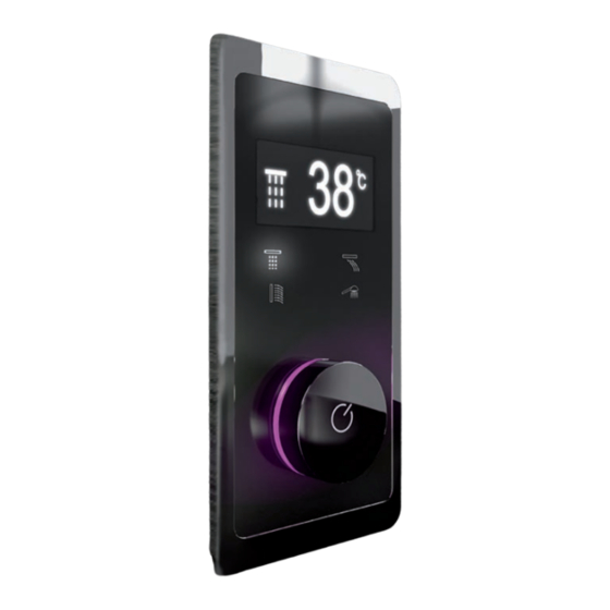
- Seite 2 ANIMIERTES DISPLAY ANIMATED DISPLAY VERBRAUCHER OUTLETS SOF T TOUCH TASTEN BUTTONS TEMPERATURANZEIGE ÜBER LED FARBVERLAUF TEMPERATURE SENSITIVE COLOUR GRADIENT LED COLD...
- Seite 3 VOLLELEKTRONISCHE ARMATUR MIT DIGITALANZEIGE FÜR BIS ZU 4 VERBRAUCHER Die Montageanleitung beinhaltet Vorgaben für die vorschriftsgemäße Installation der iFlow. Die Produktgarantie erlischt, wenn das Produkt nicht gemäß der Montageanleitung mit Einbaukörper für Steuerung und Regelung • installiert wird. Die Montage ist nur durch qualifi zierte Sanitärinstallations-Fachbetriebe intuitiver Bedienkomfort dank Softtouch Tasten und Digitaldisplay •...
- Seite 4 TECHNISCHE ZEICHNUNG DE LIEFERUMFANG 4,50 G1/2" 3xG1/2" 4xG1/2" 1. Mischeinheit 6. Mini-DIN-Kabel (7,5 m) 11. 4 x Innensechskant Senkschraube M3 x 6 mm 2. Umstelleinheit 7. Netzteil 12V 12. 4 x Senkkopfschrauben M4,2 x 38 mm 3. Bedieneinheit 8. O-Ring 120 x 1,2 mm 13.
- Seite 5 INSTALLATIONSORTE Um problemlosen Betrieb und Wartung 1.1 Kunststoff rohr unter Putz für Steuerungskabel (Mini-DIN) zwischen Einstell- und Bedien- zu gewährleisten, muss die iFlow leicht einheit verlegen (Kunststoff rohr nicht im Lieferumfang enthalten). zugänglich installiert werden. Misch- ACHTUNG: Durchmesser des Mini-DIN-Kabels beachten! und Umstelleinheit im Idealfall in einem Verteilerschrank oder unter Putz –...
-
Seite 6: Setzen Des Montagekastens Für Bedieneinheit
MONTAGEANLEITUNG SETZEN DES MONTAGEKASTENS FÜR BEDIENEINHEIT MONTAGE VON UMSTELL UND MISCHEINHEIT 76 mm 4 x Senkkopfschrauben M4,2 x 38 mm Tiefe des Montagekastens: 36 mm Zugabe für Mini-Din Anschlüsse: 40 mm VERTIEFUNG FÜR MONTAGEKASTEN ACHTUNG: Montagetiefe beachten! Für die Mini-DIN-Anschlüsse mindestens 40 mm zur Tiefe des Montagekastens hinzugeben! 2.2 Befestigungslöcher bohren - Dübel setzen... -
Seite 7: Montage Der Bedieneinheit
MONTAGEANLEITUNG MONTAGE DER BEDIENEINHEIT ANSCHLIESSEN DER WASSERLEITUNGEN UND VERBRAUCHER Rückansicht O-Ring Rückansicht 4.1 O-Ring (im Bild blau) von der Rückseite aus über die Bedieneinheit ziehen, bis dieser an der Frontplatte 5.1 ACHTUNG: Anschlusssymbole auf der Umstelleinheit anliegt beachten! 4.2 Interne Mini-DIN-Anschlüsse der Bedieneinheit für - Nicht verwendete Ausgangsanschlüsse mit Temperaturwahl und Anzeige miteinander verbinden Verschlusskappen G ½“... - Seite 8 MONTAGEANLEITUNG ANSCHLIESSEN DER WASSERLEITUNGEN UND VERBRAUCHER VERBINDEN DER ANSCHLÜSSE FÜR DIE ELEKTRONISCHE STEUERUNG 7.1 Mini-DIN-Anschluss der Umstelleinheit mit Mini-DIN-Anschluss der Bedieneinheit verbinden 7.2 Mini-DIN-Anschluss der Mischeinheit mit Mini-DIN-Anschluss der Umstelleinheit verbinden 7.3 Netzteil mit Umstelleinheit verbinden 6.1 Siebdichtungen G ½“ in KW- und WW- Zulauf einsetzen 6.2 KW- und WW-Zulauf (G ½“) an Mischeinheit anschließen (Anschlusssymbole beachten!) 6.3 Mischwasserzuleitung zwischen Mischeinheit und...
- Seite 15 R AIN STEINBERG GmbH Schiess-Str. 30 D-40549 Düsseldorf Tel. +49 (0)211 520 249-0 Fax: +49 (0) 211 520 249 -20 info@steinberg-armaturen.de www.steinberg-armaturen.de Der Hersteller behält sich das Recht vor, ohne vorherige Ankündigung technische Änderungen vorzunehmen. The manufacturer reserves the right to make technical modifi cations without prior notice.