Pilz PSEN i1 Betriebsanleitung
Quicklinks
20 776-05
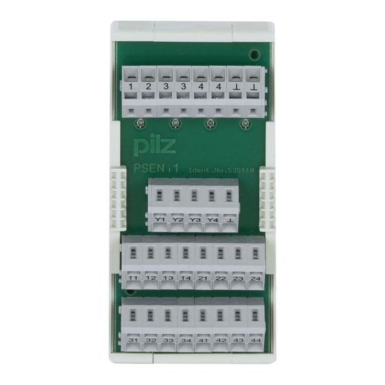
PSEN i1
Die Schnittstelle PSEN i1
Mit Hilfe der Schnittstelle PSEN i1 lassen
sich mehrere Sicherheitssensoren oder
Positionsschalter an Schutztürwächter oder
Sicherheitssteuerungen anschließen und
auswerten. An das PSEN i1 dürfen ange-
schlossen werden:
• Sicherheitssensoren der Serie PSEN 2:
PSEN 2.1a-20, PSEN 2.1b-20, PSEN 2.1b-
26, PSEN 2.1p-10, PSEN 2.1p-11, PSEN
2.1p-20, PSEN 2.1p-26, PSEN 2.1p-21,
PSEN 2.1p-24, PSEN 2.2p-20, PSEN 2.2p-
21, PSEN 2.2p-24
• Positionsschalter mit Öffner-/Schließer-
Kombination
Das PSEN i1 darf angeschlossen werden an:
• Schutztürwächter der Produktfamilie
PNOZelog: PNOZ e3.1p, PNOZ e3vp 10,
PNOZ e3vp 300, PNOZ e5.13p
• kompakte Sicherheitssteuerungen der
Systemfamilie PSS
• modulare Sicherheitssteuerungen der
Systemfamilie PSS mit geeigneter
zentraler Eingabebaugruppe
• SafetyBUS p-fähige Sicherheits-
steuerungen der Systemfamilie PSS und
dezentraler Eingabebaugruppe (I/OD)
• modulare Sicherheitssysteme der System-
familie PNOZmulti
Wichtig: Durch die Reihenschaltung
von PSENmag verringert sich der
mögliche Diagnosedeckungsgrad und
dadurch die maximal erreichbaren
Sicherheitsklassifizierungen nach:
• EN 60947-5-3 von PDF-M auf PDF-S
• EN ISO 13849-1 von PLe auf PLc
• EN 62061 von SIL3 auf SIL1
• EN 954-1 von Kat.4 auf Kat.3
Zu Ihrer Sicherheit
Die Schnittstelle PSEN i1 erfüllt alle not-
wendigen Bedingungen für einen sicheren
Betrieb.
Beachten Sie jedoch nachfolgend aufgeführte
Sicherheitsbestimmungen:
• Installieren und nehmen Sie das Gerät nur
dann in Betrieb, wenn Sie mit dieser
Betriebsanleitung und den geltenden
Vorschriften über Arbeitssicherheit und
Unfallverhütung vertraut sind.
• Verwenden Sie das Gerät nur gemäß seiner
Bestimmung. Beachten Sie dazu auch die
Werte im Abschnitt "Technische Daten".
• Halten Sie beim Transport, bei der
Lagerung und im Betrieb die Bedingungen
nach EN 60068-2-6, 01/00 ein (siehe
"Technische Daten").
• Öffnen Sie nicht das Gehäuse und nehmen
Sie auch keine eigenmächtigen Umbauten
vor.
Beachten Sie unbedingt die Warnhinweise in
den anderen Abschnitten dieser Anleitung.
Diese Hinweise sind optisch durch Symbole
hervorgehoben.
Wichtig: Beachten Sie die Sicher-
heitsbestimmungen, sonst erlischt
jegliche Gewährleistung.
The interface PSEN i1
The PSEN i1 interface enables several safety
sensors or position switches to be connected
to safety gate monitors or programmable
safety systems and evaluated. The following
may be connected to the PSEN i1:
• Safety sensors from the PSEN 2 series:
PSEN 2.1a-20, PSEN 2.1b-20, PSEN 2.1b-
26, PSEN 2.1p-10, PSEN 2.1p-11, PSEN
2.1p-20, PSEN 2.1p-26, PSEN 2.1p-21,
PSEN 2.1p-24, PSEN 2.2p-20, PSEN 2.2p-
21, PSEN 2.2p-24
• Position switches with N/C / N/O
combination in safety circuits
The PSEN i1 may be connected to:
• Safety gate monitors from the PNOZelog-
range: PNOZ e3.1p, PNOZ e3vp 10,
PNOZ e3vp 300, PNOZ e5.13p
• Compact programmable safety systems
from the PSS-range
• Modular programmable safety systems from
the PSS-range with an appropriate
centralised input module
• SafetyBUS p-compatible programmable
safety systems from the PSS-range and
decentralised input module (I/OD)
• modular safety systems of the PNOZmulti
range
Notice: Connecting the PSENmag in
series reduces the potential diagnostic
coverage and therefore the maximum
achievable safety classifications in
accordance with:
• EN 60947-5-3 from PDF-M to PDF-S
• EN ISO 13849-1 from PLe to PLc
• EN 62061 from SIL3 to SIL1
• EN 954-1 from Cat.4 to Cat.3
For your safety
The PSEN i1 interface meets all the
necessary conditions for safe operation.
However, always ensure the following safety
requirements are met:
• Only install and commission the unit if you
are familiar with the information in these
operating instructions, as well as the
relevant regulations concerning health and
safety at work and accident prevention.
• Only use the unit for the purpose for which it
is intended. Please note also the values
stated in the "Technical details" section.
• Transport, storage and operating conditions
should all conform to EN 60068-2-6, 01/00
(see "Technical details").
• Do not open the housing or make any
unauthorised modifications.
You must observe the warning notes given in
other parts of these operating instructions.
These notes are highlighted via symbols.
Notice: Failure to comply with the
safety requirements will render the
guarantee invalid.
- 1 -
L'interface PSEN i1
L'interface PSEN i1 permet le raccordement
de plusieurs capteurs de sécurité ou interrup-
teurs de position sur un relais de contrôle de
protecteurs mobiles ou un automate de
sécurité. Les éléments suivants peuvent être
raccordés au PSEN i1 :
• capteurs de sécurité de la gamme PSEN 2 :
PSEN 2.1a-20, PSEN 2.1b-20, PSEN 2.1b-
26, PSEN 2.1p-10, PSEN 2.1p-11, PSEN
2.1p-20, PSEN 2.1p-26, PSEN 2.1p-21,
PSEN 2.1p-24, PSEN 2.2p-20, PSEN 2.2p-
21, PSEN 2.2p-24
• interrupteurs de position avec contact O/F
Le PSEN i1 peut être raccordé à :
• blocs logiques de la gamme PNOZelog :
PNOZ e3.1p, PNOZ e3vp 10, PNOZ e3vp
300, PNOZ e5.13p
• automates de sécurité compacts de la
gamme PSS
• automates de sécurité modulaires de la
gamme PSS avec cartes d'entrée adaptées
• automates de sécurité avec réseau
SafetyBUS p de la gamme PSS et module
d'entrée déporté (I/O)
• systèmes de sécurité modulaires de la
gamme PNOZmulti
Important : Le montage en série du
PSENmag réduit la couverture du
diagnostic et ainsi la classe de sécurité
pouvant être atteinte selon les normes
suivantes :
• EN 60947-5-3 de PDF-M à PDF-S
• EN ISO 13849-1 de PLe à PLc
• EN 62061 de SIL3 à SIL1
• EN 954-1 de la cat.4 à la cat.3
Pour votre sécurité
L'interface PSEN i1 satisfait à toutes les
conditions nécessaires pour un fonctionne-
ment sécuritaire.
Toutefois, vous êtes tenu de respecter les
prescriptions de sécurité suivantes :
• Vous n'installerez l'appareil et ne le mettrez
en service qu'après vous être familiarisé
avec le présent manuel d'utilisation et les
prescriptions en vigueur sur la sécurité du
travail et la prévention des accidents.
• N'utilisez l'appareil que conformément à sa
définition. Respectez les valeurs indiquées
dans les "Caractéristiques techniques".
• Pour le transport, le stockage et l'utilisation,
respectez les exigences de la norme
EN 60068-2-6, 01/00 (voir "Caractéristiques
techniques")
• N'ouvrez pas le boîtier et n'effectuez pas de
modifications non autorisées.
Respectez impérativement les avertissements
dans les autres paragraphes du présent
manuel d'utilisation. Ces avertissements sont
signalés par des symboles visuels.
Important : Respectez les consignes
de sécurité, sinon la garantie devient
caduque.

Inhaltszusammenfassung für Pilz PSEN i1
- Seite 1 • interrupteurs de position avec contact O/F Kombination The PSEN i1 may be connected to: Le PSEN i1 peut être raccordé à : Das PSEN i1 darf angeschlossen werden an: • Safety gate monitors from the PNOZelog- • blocs logiques de la gamme PNOZelog : •...
- Seite 2 Description du fonctionnement Das PSEN i1 schaltet die 4 Öffnerkreise der The PSEN i1 switches the 4 N/C circuits of Le PSEN i1 met en parallèle les 4 contacts à angeschlossenen Sicherheitssensoren/ the connected safety sensors/position ouverture des capteurs de sécurité/...
- Seite 3 PNOZ e3.1p oder PNOZ e3vp und PNOZ e5.13p: PNOZ e5.13p : • Connect the PSEN i1 to one of the named • Reliez le PSEN i1 avec un des relais PNOZ e5.13p: • Verbinden Sie das PSEN i1 mit einem der safety gate monitors.
- Seite 4 • Connect the safety sensors/position • Câblez les capteurs de sécurité/interrup- Positionsschalter mit dem PSEN i1. switches to the PSEN i1. teurs de position sur le PSEN i1. Wichtig: Beachten Sie beim Notice: When connecting less than 4 Important : en cas de raccordement...
- Seite 5 • Beschalten Sie bei Bedarf die Diagnose- • If required, connect the diagnostic outputs • Câblez si nécessaire les sorties Y1 ... Y4 ausgänge Y1 ... Y4 des PSEN i1. Y1 ... Y4 on the PSEN i1. du PSEN i1.
- Seite 6 Evaluation (PNOZ e3.1p) of 6 safety sensors Unité de contrôle (PNOZ e3.1p) avec 6 heitssensoren über 3 in Reihe geschaltete via 3 PSEN i1 units connected in series. capteurs de sécurité PSEN 2.1p-10 câblés à PSEN i1. l’aide de 3 PSEN i1 en série...
- Seite 7 D D D D D F F F F F Abmessungen in mm (") Dimensions in mm (") Dimensions en mm (") D D D D D F F F F F Anschlussbelegung Connector pin assignment Affectation des raccords - 7 -...
- Seite 8 0224 2360180, Fax: 0224 2360184, E-Mail: pilz.tr@pilz.de Pilz Automation Safety L.P ., 734 354-0272, Fax: 734 354-3355, E-Mail: info@pilzusa.com www.pilz.com ✆ Pilz GmbH & Co. KG, Sichere Automation, Felix-Wankel-Straße 2, 73760 Ostfildern, Deutschland, +49 711 3409-0, Fax: +49 711 3409-133, E-Mail: pilz.gmbh@pilz.de - 8 -...