Herunterladen Inhalt Inhalt Diese Seite drucken
Inhaltsverzeichnis

Werbung

Verfügbare Sprachen

Verfügbare Sprachen

Differential controller
ENG
SGC16H: 1 output, 2 inputs
Differenzregler
DEU
SGC16H: 1 Ausgang, 2 Eingänge
Diferenčný regulátor
SVK
SGC16H: 1 výstup, 2 vstupy
SGC16H
A1360_1
MJ/OD
06/2018

Werbung

Inhaltsverzeichnis
loading

Inhaltszusammenfassung für Thermo Solar SGC16H

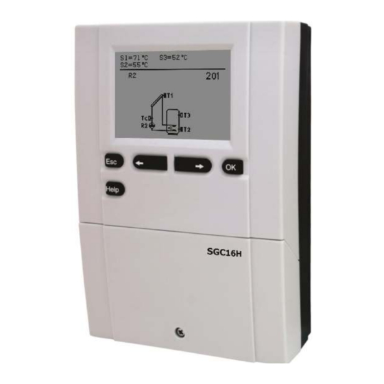
  • Seite 1 Differential controller SGC16H: 1 output, 2 inputs Differenzregler SGC16H: 1 Ausgang, 2 Eingänge Diferenčný regulátor SGC16H: 1 výstup, 2 vstupy SGC16H A1360_1 MJ/OD 06/2018...
  • Seite 2 A1360_1 MJ/OD 06/2018...
  • Seite 3 Differential controllers SGC16H Differenzregler SGC16H Diferenčný regulátor SGC16H A1360_1 MJ/OD 06/2018...
  • Seite 4 Differential controllers SGC16H INTRODUCTION Differential controllers SGC16H are modern designed, microprocessor-driven devices made with digital and SMT technology. These devices are intended for regulating domestic hot water warming by means of solar collectors or for regulating domestic hot water warming by means solid fuel boiler, electric heater or other energy resources.
  • Seite 5: Inhaltsverzeichnis

    CONTENTS USER MANUAL Appearance of controller SGC16H ................6 Initial controller setup ....................7 Graphic LCD display ..................... 9 Description of symbols shown on the display ............10 Display for help, notices and warnings ..............12 Menu entry and navigation .................. 13 Menu structure and description ................
  • Seite 6: User Manual

    USER MANUAL APPERANCE OF CONTROLLER SGC16H Screw for fastening the cover Graphic display Button Button (menu entry, confirmation of selection) (Esc - return back) Button (Help) Button (move to right, increasing) Button Cover for connection area (move to left, decreasing)
  • Seite 7: Initial Controller Setup

    INITIAL CONTROLLER SETUP SGC16H differential controllers are equipped with an innovative solution, which allows initial setup of the controller in only two steps. When you connect the controller to the power supply for the first time, the software ver- sion is shown. Next, the first step appears on the screen.
  • Seite 8: Controller Reset

    STEP 2 Next, you select a hydraulic scheme for the controller function. Move between schemes by means of buttons Confirm the selected scheme by pressing the button. After you selected the scheme, the controller requires confirmation of the selection by pressing the button.
  • Seite 9: Graphic Lcd Display

    GRAPHIC LCD DISPLAY All important data of controller operation are shown on the graphic LCD display. DESCRIPTION AND DESIGN OF THE MAIN DISPLAY: Controller mode Measured Active time program temperatures Active functions State of output Warnings Measured Time Diagram temperatures, of hydraulic state of output date...
  • Seite 10: Description Of Symbols Shown On The Display

    DESCRIPTION OF SYMBOLS SHOWN ON THE DISPLAY All important data about controller operation are seen on the LCD display. We browse through data by means of buttons OPERATION MODE SYMBOLS Symbol Description Controller operates in automatic mode Controller operates automatically according to program timer .
  • Seite 11 TEMPERATURE AND OTHER DATA SYMBOLS Symbol Description Solar collectors’ temperature Temperature of storage tank or heat accumulator - bottom Temperature of storage tank or heat accumulator - top Liquid fuel boiler temperature Solid fuel boiler temperature Stand- pipe or return- pipe temperature Measured temperature Set point or calculated temperature Temperature sensors T1, T2, T3, T4 und T5.
  • Seite 12: Display For Help, Notices And Warnings

    DISPLAY FOR HELP, NOTICES AND WARNINGS Press button to open the screen for help, notices and warnings is opened. Available posibilities: Short manual Short manual for use of the controller. Controller version Overview of controller type and software version. Notices Log of maximum temperatures exceeds and activated protection functions.
  • Seite 13: Menu Entry And Navigation

    MENU ENTRY AND NAVIGATION The menu is simplified with the help of graphic symbols. To enter the menu, press the button Move around the menu using the buttons , with the button you confirm your selection. By pressing the button you return to the previous screen.
  • Seite 14: Menu Structure And Description

    MENU STRUCTURE AND DESCRIPTION TEMPERATURE SETTINGS Set-point temperature in d. h. w. storage tank or heat accumulator USER FUNCTIONS One - time domestic hot water warming Holiday operation mode Cancelation of user function OPERATION MODE Automatic operation Controller operation - Stand-by Manual operation mode TIME PROGRAMS SELECTION OF ACTIVE TIME PROGRAM...
  • Seite 15 Time program #2. Time program #3. Time program #4. BASIC SETTINGS Language selection Time and date DISPLAY SETTINGS Duration of active display illumination and menu autoexit Intensity of active display illumination Intensity of inactive display illumination Display contrast DATA OVERVIEW Numeric and graphic display of acquired energy Diagrams of measured temperatures for last week...
  • Seite 16 SERVICE PARAMETERS Service parameters Service parameters Service parameters PARAMETERS FOR HEAT METERING FACTORY SETTINGS Reset of all controller parameters Reset of time programs Reset of all controller settings and restart of initial setup Save user settings Load user settings User and settings manual A1360_1 MJ/OD 06/2018...
  • Seite 17: Temperature Settings

    TEMPERATURE SETTINGS In the menu “TEMPERATURE SETTINGS” you can set the set-point temperature for the sen- sors shown. By pressing buttons you choose the required temperature, and a new window opens: Current value of set-point temperature Sensor location (numeric mode) Value of the last confirmed setting Graphic review...
  • Seite 18: User Functions

    USER FUNCTIONS User functions enable additional comfort and benefits when using the controller. In menu, the following user functions are available: One-time domestic hot water warming Use this function when you want to immediately turn on the d. h. w. warming. By pressing buttons select function and activate it by pressing the but- You leave settings by pressing the button...
  • Seite 19: Operation Mode Selection

    OPERATION MODE SELECTION In group “OPERATION MODE” select the required controller operation mode. You can select between automatic mode, controller switch-off and manual mode. You choose the required mode by pressing buttons and confirm it by press- ing button You exit the setting by pressing button Description of operation mode: Automatic mode Stand-by...
  • Seite 20: Time Program Settings

    TIME PROGRAM SETTINGS In menu “TIME PROGRAMS” you have two submenus - selection of active program timer and program time editor Selection of active program timer In the “SELECTION OF ACTIVE PROGRAM TIMER” menu are five settings: WITHOUT PROGRAM TIMER Controller operates without program timer.
  • Seite 21 Modifying the time programs: To modify a time program first press buttons to select and to open the selected time program. A new window opens: Number of time program Selected day Time axis: - time program review for selected day Time program copying Time program editing First, by pressing buttons...
  • Seite 22 Time program copying A new window opens which shows the time program for a selected day. At the top is a field where you can select a day or more days together in which you want to copy the time program. A day or group of days are selected by pressing buttons For copying press button Finish copying by pressing button...
  • Seite 23: Basic Settings

    BASIC SETTINGS “BASIC SETTINGS” menu is intended for language, time, date and display settings. Language selection The required user language is selected by pressing buttons and confirmed with button You exit the settings by pressing button Time and date setting You set the exact time and date in the following manner: By pressing buttons move among...
  • Seite 24: Display Settings

    Display settings In the “DISPLAY SETTINGS” menu are four settings: TIME OF ACTIVE ILLUMINATION AND MENU AUTOEXIT Time of active (more intensive) screen illumination and autoexit from menu to the main screen. INTENSITY OF ACTIVE ILLUMINATION INTENSITY OF INACTIVE ILLUMINATION DISPLAY CONTRAST By pressing buttons you select and confirm required setting.
  • Seite 25: Data Overview

    DATA OVERVIEW In the menu “DATA OVERVIEW” there are icons to access the following data on control- ler performance: NUMERIC AND GRAPHIC REVIEW OF ACQUIRED ENERGY There is an extract of acquired energy by years, months and weeks. DIAGRAMS OF MEASURED TEMPERATURES FOR LAST WEEK Graphic overview of temperature by day for each sensor.
  • Seite 26: Service Manual

    SERVICE MANUAL CONTROLLER PARAMETERS AND AUXILIARY TOOLS All additional settings and adjustments of controller performance are carried out by means of parameters. In controller parameter settings menu there are three selectable groups: Basic parameters Service parameters Heat metering parameters You can only see those parameters which have an effect on the selected hy- draulic scheme.
  • Seite 27 Table with description of parameters Para- Function Setting range Default value meter 3 ÷ 30 K P1.1 SWITCH -ON DIFFERENCE 1 depends on selected scheme 1 ÷ 20 K P1.2 SWITCH -OFF DIFFERENCE 1 depends on selected scheme 1 ÷ 30 K P1.9 HYSTERESIS FOR SENSOR T1 depends on selected scheme...
  • Seite 28: Service Parameters

    SERVICE PARAMETERS Service parameters are arranged in groups S1, S2 and S3. With service parameters it is possible to activate or select many additional functions and adaptations of controller performance. When you select the required parameter group in the menu, a new screen opens: Parameters are locked Parameter value...
  • Seite 29 Table with description of parameters Para- Function Parameter description Setting range Default meter value S1.1 HYDRAULIC SCHEME Selection of hydraulic scheme. depends on type of controller S1.2 CODE FOR UNLOCKING This setting enables the change of code which is necessary to 0000 - 9999 0001 THE SERVICE SETTINGS...
  • Seite 30 Table with description of parameters Para- Function Parameter description Setting range Default meter value S2.1 PROTECTION OF MAX. When the temperature in the storage tank is higher than the set 0- NO COLLECTORS TEMPERA- point temperature plus hysteresis (P1.10), heating with the 1- YES TURE collectors stops.
  • Seite 31 Table with description of parameters Para- Function Parameter description Setting range Default meter value S3.1 SOLAR PUMP R2 OPERATI- You can set the operation mode of the R2 pump with a set- 0- ON/OFF ON MODE ting. 1- RPM 0- ON/OFF mode is used exclusively for control of classic 2- PWM pumps without speed control 3- PWM,...
  • Seite 32: Heat Metering Parameters

    HEAT METERING PARAMETERS Group W contains parameters to set the solar heat metering. The procedure for setting function parameters is the same as for service parameters (see page 28). Table with description of parameters Para- Setting range Default Function Parameter description meter value W1.1...
  • Seite 33: Heat Metering

    HEAT METERING Controllers SGC16H enable simple and advanced metering of acquired solar energy. For heat metering is necessary to have a temperature sensor installed into solar collec- tor’s return pipe - T4. Heat metering is activated with parameter W1.1=1. Medium and its mixture is set with parameter W1.2 and W1.3.
  • Seite 34: Factory Settings

    FACTORY SETTINGS In the menu “FACTORY SETTINGS” there are software tools to help with setting the controller. RESET OF ALL CONTROLLER PARAMETERS Restores all settings of parameters P1, P2, P3, S1 (except S1.1), S2, S3 and W to default values. RESET OF TIME PROGRAMS Restores default time programs.
  • Seite 35: Installation Manual

    INSTALLATION MANUAL CONTROLLER INSTALLATION The SGC controllers are installed directly on the wall or on DIN rail or in the opening of the solar group system. WALL INSTALLATION Install the regulator inside in a dry place, where it is not exposed to any strong electro- magnetic fields.
  • Seite 36: Marking And Description Of Temperature Sensors

    2. Hang the controller on the upper screw. 3. Insert the lower screw and screw it in. MARKING AND DESCRIPTION OF TEMPERATURE SENSORS TABLE: Resistance values for temperature sensors type Pt-1000 Temperature Resistance Temperature Resistance Temperature Resistance Temperature Resistance [°C] [°C] [°C] [°C]...
  • Seite 37: Controller's Electric Connection

    CONTROLLER'S ELECTRIC CONNECTION Each project with differential controller needs to base exclusively on customer design and calculations and needs to be in compliance with valid rules and regulations. Pictures, diagrams and text in this manual are intended solely as an example and the manufacturer does not accept any responsibility for them. If you use content of this manual as a base for your project, then you carry also full responsibility for it.
  • Seite 38: Flow Meter Installation

    FLOW METER INSTALLATION The flow meter is installed in the return pipe of the solar system. When installing the flow meter please refer to the user manual that is included. After installing the flow meter you have to set operation parameters in the function parameters W. CONNECTION OF A HIGH-EFFICIENCY PUMP WITH AN EXTERNAL CONTROL SIGNAL The SGC controller enables the regulation of high-efficiency pump speed with PWM exter-...
  • Seite 39: Setting The Flow In A Solar System And Testing The Control Function

    SETTING THE FLOW IN A SOLAR SYSTEM AND TESTING THE CONTROL FUNC- TION Based on the surface of the installed collectors, the rated system flow has to be deter- mined, ranging from 0.5 to 1.2 l/min for each square meter of solar collectors or according to the manufacturer's instructions (example: for 3 solar collectors with a total surface of 6 , the rated flow in the system is 5,4 l/min, with the selected flow of 0,9 l/min per square meter of a collector).
  • Seite 40: Technical Data

    TECHNICAL DATA Technical specifications - controller Dimensions (w x h x d)···················································· 113 x 163 x 48 mm Weight ········································································ 391 g Housing material ··························································· ASA Power supply voltage ···················································· 230 V ~ , 50 Hz Consumption ································································ max. 4 VA Energetic cable cross-section ··········································...
  • Seite 41: Disposal Of Old Electrical And Electronic Equipment

    DISPOSAL OF OLD ELECTRICAL & ELECTRONIC EQUIPMENT Discarding old electrical and electronic equipment (valid for EU member states and other European countries with organized separate waste collection). This symbol on the product or packaging means the product cannot be treated as a household waste and it has to be disposed of separately via designated collection facilities for old electrical and electronic equipment (OEEO).
  • Seite 42: Guarantee

    GUARANTEE This product complies with all the regulations and declared characteristics. We grant a 2 years' guarantee on the product, commencing on the date of purchase. We will eliminate any defects in the product, resulting from defects in material or manufacture, malfunctions or imperfections.
  • Seite 43: Einleitung

    Differenzregler SGC16H EINLEITUNG Differenzregler SGC16H sind moderne, von Mikroprozessoren gesteuerte Geräte. Die Differenzregler benutzen Digitale und SMT- Technologie. Diese Geräte eignen sich für die Regulierung der Brauchwassererwärmung durch Solar- kollektoren oder für die Regulierung der Brauchwassererwärmung mit Festbrennstoffkes- seln, elektrischen Heizungen oder anderen Energiequellen.
  • Seite 44 INHALT BEDIENUNGSANLEITUNGEN Aussehen des Reglers SGC16H ................45 Reglereinstellung bei Ersteinschaltung des Reglers ..........46 Graphischer LCD Display und Datendarstellung............. 48 Beschreibung der Symbole am Display ..............49 Symbole zur Darstellung der Betriebsart ............49 Symbole zur Darstellung der Temperatur und anderer Daten ......50 Warnsymbole ....................
  • Seite 45: Bedienungsanleitungen

    BEDIENUNGSANLEITUNGEN AUSSEHEN DES REGLERS SGC16H Deckelbefestigungsschraube Graphisches Display Taste Taste (Menüanwahl, Anwahlbestätigung) (Esc – zurücksetzen) Taste Taste (Hilfe) (Bewegung nach rechts, Wertzunahme) Gerätdeckel Taste (Bewegung nach links, Wertabnahme). Bedienungs- und Einstellungsanleitungen A1360_1 MJ/OD 06/2018...
  • Seite 46: Reglereinstellung Bei Ersteinschaltung Des Reglers

    REGLEREINSTELLUNG BEI ERSTEINSCHALTUNG DES REGLERS Die Differenzregler SGC16H beinhalten eine innovative Lösung, die eine Einstellung des Reglers in nur zwei Schritten ermöglicht. Bei der Ersteinschaltung des Reglers ans Netz wird, nach dem Anzeigen der Programm- version, auf dem Display der 1. Schritt zur Einstellung des Reglers angezeigt.
  • Seite 47 2. SCHRITT Jetzt wird das Hydraulische Schema des Reglerbetriebs ausgewählt. Zwischen den Schemen bewegen Sie sich mit den Tasten . Das angewählte Sche- ma wird mit Drücken auf die Taste bestätigt. Nach der Bestätigung des ausgewählten Schemas, ver- langt der Regler noch eine Bestätigung der richtigen Aus- wahl mit der Taste Haben Sie versehentlich das falsche Schema angewählt, blättern Sie zurück, bis zur Auswahl des Schemas mit...
  • Seite 48: Graphischer Lcd Display Und Datendarstellung

    GRAPHISCHER LCD DISPLAY UND DATENDARSTELLUNG Alle wichtigen Daten sind auf dem graphischen LCD Display ersichtlich. BESCHREIBUNG UND AUSSEHEN DES HAUPTDISPLAYS Die Betriebsart des Reglers Ist-Temperatur Aktives Zeitprogramm Zustand der Aktive Funktionen Relaisausgänge Gemessene Zeit Warnungen Temperaturen, Graphische Darstellung Zustand des des Hydraulikschemas Datum Relaisaus-...
  • Seite 49: Beschreibung Der Symbole Am Display

    BESCHREIBUNG DER SYMBOLE AM DISPLAY SYMBOLE ZUR DARSTELLUNG DER BETRIEBSART Symbol Beschreibung Regler arbeitet im automatischen Modus Regler arbeitet im automatischen Modus nach dem Zeitprogramm oder ON und OFF stellen den aktuellen Stand des Zeitprogramms dar. Manueller Betrieb Stand-by Einmaliges Einschalten der Brauchwassererwärmung Urlaubmodus eingeschaltet Rückkühlung des Speichers Überhitzungsschutz der Sonnenkollektoren eingeschaltet...
  • Seite 50: Symbole Zur Darstellung Der Temperatur Und Anderer Daten

    SYMBOLE ZUR DARSTELLUNG DER TEMPERATUR UND ANDERER DATEN Symbol Beschreibung Sonnenkollektortemperatur Temperatur des Brauchwassererwärmers oder des Wärmespeichers - unten Temperatur des Brauchwassererwärmers oder des Wärmespeichers - oben Temperatur des Flüssigbrennstoffkessels Temperatur des Festbrennstoffkessels Vorlauftemperatur oder Rücklauftemperatur Ist-Temperatur Soll-Temperatur oder ausgerechnete Temperatur Fühlertemperatur T1, T2, T3, T4 und T5 T1, T2, T3, T4, T5 WARNSYMBOLE...
  • Seite 51: Hilfebildschirm, Meldungen Und Warnungen

    HILFEBILDSCHIRM, MELDUNGEN UND WARNUNGEN Mit dem Drücken der Taste können Sie den Hilfebildschirm, Meldungen und Hinwei- se abrufen. Es öffnet sich ein neues Fenster mit folgenden Möglichkeiten. Verfügbare Möglichkeiten: Kurze Einleitungen Kurze Einleitungen für Regler betrieb. Version des Reglers Anzeige des Models und der Softwareversion des Reglers. Meldungen Liste der Überschreitungen der maximalen Temperatur und der Aktivierun- gen der Schutzfunktionen.
  • Seite 52: Öffnen Des Menüs Und Der Navigation

    ÖFFNEN DES MENÜS UND DER NAVIGATION Das Menü der Benutzereinstellungen wird mit Hilfe von graphischen Symbolen ausge- führt. Um das Menü zu öffnen, drückt man die Taste . Innerhalb des Menüs bewegt man sich mit den Tasten , mit der Taste wird die Wahl bestätigt.
  • Seite 53: Menüstruktur Und Menübeschreibung

    MENÜSTRUKTUR UND MENÜBESCHREIBUNG TEMPERATUREINSTELLUNG Soll-Temperatur des Brauchwassererwärmers oder des Wärmespeichers BENUTZERFUNKTIONEN Einmaliges Einschalten der Brauchwassererwärmung Urlaubmodus Abschaltung der Benutzerfunktion BETRIEBSART Automatikbetrieb Stand-by Manueller Betrieb ZEITPROGRAMME ZEITPROGRAM AUSWAHL Ohne Zeitprogramm Zeitprogramm Zeitprogramm Zeitprogramm Zeitprogramm ZEITPROGRAM EINSTELLUNG Zeitprogramm Bedienungs- und Einstellungsanleitungen A1360_1 MJ/OD 06/2018...
  • Seite 54 Zeitprogramm Zeitprogramm Zeitprogramm GRUNDEINSTELLUNGEN Sprachenauswahl Zeit und Datum DISPLAY EINSTELLUNG Dauer der aktiven Displaybeleuchtung Intensität der aktiven Displaybeleuchtung Intensität der inaktiven Displaybeleuchtung Kontrast des Displays DATEN KONTROLLE Numerische und graphische Darstellungen der gewonnenen Energie Graphische Darstellungen der gemessenen Temperaturen für die vergan- gene Woche Graphische Darstellungen der Temperaturen des aktuellen Tages Betriebsstundenzähler der Relaisausgänge...
  • Seite 55 WARTUNGSPARAMETER Wartungsparameter 1 Wartungsparameter 2 Wartungsparameter 3 ENERGIEMESSUNG WERKSEINSTELLUNGEN Reset der Parameter des ausgewählten Hydraulikschemas Reset aller Zeitprogramme Reset der Reglereinstellungen Benutzereinstellungen speichern Benutzereinstellungen laden Bedienungs- und Einstellungsanleitungen A1360_1 MJ/OD 06/2018...
  • Seite 56: Temperatureinstellung

    TEMPERATUREINSTELLUNG Im Menü „TEMPERATUREINSTELLUNG“ sind nur die Werte angezeigt, bei welchen man am ausgewählten Hydraulikschema die Soll-Temperatur einstellen kann. Wenn mit den Tasten die gewünschte Temperatur angewählt wird, öffnet sich eine neue Displayanzeige: Momentaner Wert der Soll-Temperatur Montagestelle (numerische Darstellung) des Fühlers Zuletzt gespeicherte Werteinstellung...
  • Seite 57: Benutzerfunktionen

    BENUTZERFUNKTIONEN Benutzerfunktionen ermöglichen einen zusätzlichen Komfort und Funktionalität beim Ge- brauch des Reglers. Im Menü stehen Ihnen folgende Benutzerfunktionen zur Verfügung: Einmaliges Einschalten der Brauchwassererwärmung Diese Funktion benutzt man, wenn man ungeachtet anderer Kriterien, sofort die Brauch- wassererwärmung einschalten möchte. Mit den Tasten wählt man die Funktion aus und schaltet sie mit der Taste...
  • Seite 58: Betriebsartenwahl

    BETRIEBSARTENWAHL Unter der Gruppe „BETRIEBSART“ wird die gewünschte Betriebsart des Reglers ausge- wählt. Die gewünschte Betriebsart wählt man mit den Tasten aus und bestä- tigt sie mit der Taste Das Einstellen verlässt man mit dem Drücken der Taste Beschreibung der Betriebsarten: Automatikbetrieb Stand-by mode Der Regler funktioniert nicht und schaltet alle Relaisausgänge aus.
  • Seite 59: Zeitprogramme

    ZEITPROGRAMME Im Menü „ZEITPROGRAMME„ haben sie zwei Untermenüs – Auswahl der aktiven Zeit- programme und dem Zeitprogramm – Editor Auswahl des Aktiven Zeitprogrammes In dem “AUSWAHL DES AKTIEVEN ZEITPROGRAMMES” Menü, sind fünf Einstellungs- möglichkeiten. OHNE ZEITPROGRAMM Betrieb ohne Zeitprogramm. ZEITPROGRAMM #1 Betrieb nach dem Zeitprogram #1.
  • Seite 60: Zeitprogramm Einstellen

    Änderungen in den Zeitprogrammen: Um das Zeitprogramm zu ändern, muss man erst mit den Tasten das gewünschte Zeitprogramm anwählen. Eine neue Anzeige erscheint: Nr. des Zeitprogramms Ausgewählter Tag Zeitlinie - Der Zeitprogramm für den jeweiligen Tag wird angezeigt. Zeitprogramm kopieren Zeitprogramm einstellen Erst mit den Tasten den Tag, an dem die Veränderung im Zeitpro-...
  • Seite 61: Zeitprogramm Kopieren

    Zeitprogramm kopieren Eine neue Anzeige mit dem Zeitprogramm für den je- weiligen Tag öffnet sich. Auf der oberen Displayhälfte befindet sich das Feld für die Wahl des Wochentages oder Gruppe der Tage in die man das Zeitprogramm kopieren möchte. Die Wahl des Wochentages oder Gruppe der Tage wählt man mit den Tasten aus.
  • Seite 62: Grundeinstellungen

    GRUNDEINSTELLUNGEN Das Menü „GRUNDEINSTELLUNGEN“ dient zur Einstellung der Sprache, der genauen Zeit und des genauen Datums sowie der Einstellung des Displays. Sprachenauswahl Die Soll- Sprache wird mit den Tasten angewählt und mit der Taste bestätigt. Das Einstellen verlässt man mit dem Drücken der Taste Die genaue Zeit- und Datumseinstellung Die genaue Zeit und das genaue Datum wird wie folgt eingestellt: Mit den Tasten...
  • Seite 63: Display Einstellung

    DISPLAY EINSTELLUNG Im Menü für die „DISPLAY EINSTELLUNG“ stehen Ihnen 4 Einstellungen zur Verfügung und zwar: ZEIT DER AKTIVEN DISPLAY BELEUCHTUNG UND AUTOMATISCHES VERLASSEN DES MENÜS Zeit der Aktiven (intensivere) Display Beleuchtung und Automatisches Verlassen des Menüs ins Hauptmenü. INTENSITÄT DER AKTIVEN DISPLAYBELEUCHTUNG INTENSITÄT DER INAKTIVEN DISPLAYBELEUCHTUNG KONTRAST DES DISPLAYS Wenn mit den Tasten...
  • Seite 64: Daten Kontrolle

    DATEN KONTROLLE Im Menü „DATEN KONTROLLE“ befinden sich Icons, die Ihnen einen Zugang zu den folgen- den Betriebsarten des Reglers ermöglichen: NUMERISCHE UND GRAPHISCHE DARSTELLUNG DER GEWONNENEN ENERGIE Darstellung der gewonnenen Energie pro Jahre, Monate und Wochen. GRAPHISCHE DARSTELLUNGEN DER GEMESSENEN TEMPERATUREN FÜR DIE VERGANGENE WOCHE Detaillierte grafische Übersicht von Tages Fühlertemperaturen gemessen in der vergange- nen Woche.
  • Seite 65: Wartungsanleitungen

    WARTUNGSANLEITUNGEN REGLERPARAMETER Alle anderen Einstellungen und Anpassungen des Reglerbetriebes werden mit Hilfe der Reglerparameter ausgeführt. Im Menü für die Parameter- und Reglereinstellungen stehen Ihnen 3 Gruppen zur Verfügung und zwar: Grundparameter Wartungsparameter Wärmemessungparameter Es werden nur die Parameter, die sich auf das Hydraulikschema auswirken angezeigt.
  • Seite 66 Tabelle mit Beschreibung der Parameter Übernommener Wert Para- Parameterbezeichnung Einstellungs- meter bereich 3 ÷ 30 K Von Schema abhängend P1.1 EINSCHALTDIFFERENZ 1 1 ÷ 20 K Von Schema abhängend P1.2 AUSSCHALTDIFFERENZ 1 FÜHLERHYSTERESE T1 1 ÷ 30 K Von Schema abhängend P1.9 P1.10 FÜHLERHYSTERESE T2 1 ÷...
  • Seite 67: Grundparameter

    WARTUNGSPARAMETER Wartungsparameter befinden sich in der Gruppen S1, S2 und S3. Mit den Wartungspara- metern kann man den Regler einschalten und zwischen mehreren Zusatzfunktionen und Einstellungen in Reglerbetrieb entscheiden. Wenn im Menü die Gruppe der gewünschten Parameter angewählt wird, erscheint eine neue Anzeige: - Parameter sind gesperrt Parameterwert Bezeichnung...
  • Seite 68 Tabelle mit Beschreibung der Parameter Übernom- Para- Parameterbezeichnung Parameterbeschreibung Einstellungs- meter bereich mener Wert Auswahl des gewünschten Hydraulikschemas. S1.1 HYDRAULIKSCHEMA 201 - 205 ENTSPERRKODE FÜR Die Einstellung ermöglicht eine Veränderung des Kodes, S1.2 0000 - 9999 0001 notwendig für die Aufschließung der Wartungseinstellungen. (S AUFSCHLIESSUNG DER WARTUNGSEINSTEL- und F Parameter)
  • Seite 69: Wartungsparameter

    Tabelle mit Beschreibung der Parameter Übernomme- Parame- Parameterbezeich- Parameterbeschreibung Einstellungs- nung bereich ner Wert Wenn die Temperatur im Speicher höher als die Eingestellte S2.1 SCHUTZ DER MAXI- 0- AUS MALE KOLLEK- Soll- Temperatur ist + Hysterese (P1.10), schaltet das Hei- 1- EIN TORTEMPERATUR zen mit Sonnenkollektoren aus.
  • Seite 70 Tabelle mit Beschreibung der Parameter Übernom- Para- Parameterbezeich- Parameterbeschreibung Einstellungs- meter nung bereich mener Wert S3.1 BETRIEBSART DER Mit dieser Einstellung wird die Betriebsart der Pumpe R2 0- ON/OFF ausgewählt. SOLARPUMPE R2 1- RPM 0- Die ON/OFF-Betriebsart bedeutet, dass die Pumpe mit der 2- PWM maximalen Drehzahl arbeitet 3- PWM, IN-...
  • Seite 71: Wärmemessungparameter

    WÄRMEMESSUNGPARAMETER In der Gruppe W befinden sich Parameter zur Einstellung des Messgeräts der gewonne- nen Solarenergie. Das Verfahren zur Einstellung der Funktionsparameter ist gleich wie bei den Wartungseinstellungen. (Siehe Seite 67). Tabelle mit Beschreibung der Parameter Übernom- Para- Parameterbezeich- Parameterbeschreibung Einstellungsbereich meter nung...
  • Seite 72: Energiemessungen

    ENERGIEMESSUNGEN Die Regler SGC16H ermöglichen eine einfache Wärmeerfassung und eine genauere Wärmeerfassung der gewonnenen Solarenergie mit dem Volumenmessteil. Für diese Wärmeerfassung ist ein zusätzlicher Temperaturfühler im Kollektorrücklauf notwendig - T4. Die Erfassung der gewonnenen Energie wird mit der Einstellung des Parameters W1.1=1 aktiviert.
  • Seite 73: Werkseinstellungen

    WERKSEINSTELLUNGEN Im Menü „WERKSEINSTELLUNGEN“ befinden sich Softwarewerkzeuge für leichteres Einstellen des Reglers sowie Möglichkeiten für die Rücksetzung in Werkseinstellungen. RESET DER PARAMETER DES AUSGEWÄHLTEN HYDRAULIKSCHEMAS Stellt alle Parametereinstellungen P1, P2, P3, S1 (außer S1.1), S2, S3 und W auf Werkseinstel- lungen zurück.
  • Seite 74: Montageanleitungen

    Feld ausgesetzt wird. Direkt an die Wand oder die DIN Leiste oder in die Öffnung der Solargruppe des Systems montieren. WANDMONTAGE Der Regler SGC16H wird üblicherweise an die Heizraumwand montiert. Die Montage an die Wand wird wie folgt ausgeführt: 1. An die Montagestelle 2 Löcher, 6 mm Durchmesser und ca.40 mm Tiefe, bohren.
  • Seite 75: Fühlerbezeichnung Und Fühlerbeschreibung

    2. Regler mit den Schrauben befestigen. 3. Regler am unteren Befestigungsloch festschrauben. FÜHLERBEZEICHNUNG UND FÜHLERBESCHREIBUNG TABELLE: Wiederstand der Temperaturfühler Typ Pt1000 Temperatur Widerstand Temperatur Widerstand Temperatur Widerstand Temperatur Widerstand [Ω] [Ω] [Ω] [Ω] [°C] [°C] [°C] [°C] 1136 1347 1555 1155 1366 1573...
  • Seite 76: Elektrische Anbringung Des Reglers

    ELEKTRISCHE ANBRINGUNG DES REGLERS Jedes Differenzregler-Projekt muss auf Berechnungen basieren und geplant sein. Das Berechnen und Planen liegt ausschließlich in Ihren Händen und muss den geltenden Regeln gerecht sein. Die Zeichnungen und die Texte in der vor- liegenden Anleitung haben lediglich Beispielcharakter, für die der Herausgeber keine Verantwortung übernimmt.
  • Seite 77: Anbringung Des Volumenmessteils

    ANBRINGUNG DES VOLUMENMESSTEILS Das Volumenmessteil wird in die Rücklaufleitung des Solarsystems montiert. Bei der Montage befolgen Sie die beigefügten Anweisungen. Nach der Anbringung des Messge- räts ist es notwendig, die Funktionsparameter W einzustellen. ANSCHLUSS EINER HOCHEFFIZIENZ PUMPE DURCH EIN EXTERNES STEUERSIGNAL Der SGC Regler ermöglicht die Drehzahlregelung der Hocheffizienz Pumpen mit einem externen PWM oder 0 ÷...
  • Seite 78: Durchflusseinstellung Im Solarsystem Und Regler Funktiontest

    DURCHFLUSSREINSTELLUNG IM SOLARSYSTEM UND REGLER FUNKTIONSTEST Basierend auf der Oberfläche der eingebauten Kollektoren ist es notwendig, den nomina- len Durchfluss des Systems zu bestimmen. Der Durchfluss beträgt von 0,5 bis 1,2 l / min für jeden Quadratmeter Kollektorfläche oder in Übereinstimmung mit den Anweisungen des Herstellers (z.
  • Seite 79: Technische Daten

    TECHNISCHE DATEN Allgemeine technische Daten Dimension (B x H x T) ························································· 113 x 163 x 48 mm Gewicht: ·········································································· 391 g Reglergehäuse ·································································· ASA - Thermoplast Versorgungsspannung························································· 230 V ~ , 50 Hz, Leistungsaufnahme ···························································· 5 VA Netzleiter Querschnitt ·························································· 0.75 bis 1.5 mm Schutzart ·········································································...
  • Seite 80: Entsorgung Von Gebrauchten Elektrischen Und Elektronischen Geräten

    ERKLÄRUNGEN ENTSORGUNG VON GEBRAUCHTEN ELEKTRISCHEN UND ELEKTRONISCHEN GERÄTEN Entsorgung von gebrauchten elektrischen und elektronischen Geräten (Anzuwenden in den Ländern der Europäischen Union und anderen europäischen Län- dern mit einem separaten Sammelsystem für diese Geräte). Das Symbol auf dem Produkt oder seiner Verpackung weist darauf hin, dass dieses Produkt nicht als normaler Haushaltsabfall zu behandeln ist, sondern an einer Annahmestelle für das Recycling von elektrischen und elektronischen Geräten abgegeben werden muss.
  • Seite 81: Garantieerklärung

    GARANTIEERKLÄRUNG Das Gerät erfüllt alle vorgeschriebenen Vorschriften und Richtlinien. Wir gewähren eine Garantie von zwei Jahren ab Verkaufsdatum. In der Garantieffrist werden alle Fehler, die auf Material– oder Fertigungsmängel sowie Schäden oder sonstige Mängel zurückzuführen sind, behoben. Das Gerät wird, nach unserem ermessen, entweder repa- riert oder mit einem neuen ersetzt.
  • Seite 82 Diferenčný regulátor SGC16H ÚVOD Diferenčné regulátory SGC16H sú moderne navrhnuté, mikroprocesorom riadené zariadenia, ktoré sú vyrobené digitálnou a SMT technológiou. Tieto zariadenia sú určené na riadenie ohrevu pitnej vody pomocou slnečných kolektorov alebo na riadenie ohrevu vody pomocou kotla na pevné palivo, elektrického vyhrievacieho telesa alebo iných zdrojov energie.
  • Seite 83 OBSAH NÁVOD NA POUŽITIE A NASTAVENIE Vzh ad regulátorov SGC16H ................84 Úvodné nastavenie regulátora ................85 Grafický LCD displej .................... 87 Popis hlavnej obrazovky .................. 87 Popis zobrazených symbolov ................88 Symboly prevádzkového režimu ..............88 Symboly pre teploty a iné údaje ..............89 Symboly pre oznamy a upozornenia ..............
  • Seite 84: Návod Na Použitie A Nastavenie

    NÁVOD NA POUŽITIE A NASTAVENIE VZH AD REGULÁTOROV SGC16H Grafický displej Skrutka na upevnenie krytu Tlačidlo Tlačidlo (vstup do menu, potvrdenie výberu) (Esc - návrat späť) Tlačidlo (Pomoc) Tlačidlo (pohyb vpravo, zvyšovanie) Tlačidlo Kryt svorkovnice (pohyb v avo, znižovanie) Návod na použitie a nastavenie...
  • Seite 85: Úvodné Nastavenie Regulátora

    ÚVODNÉ NASTAVENIE REGULÁTORA Úvodné nastavenie regulátorov SGC16H je možné vykonať v 2 krokoch. Po prvom pripojení regulátora na napájacie napätie sa zobrazí verzia softvéru. Následne sa zobrazí obrazovka pre prvý krok úvodného nastavenia. KROK 1 Použitím tlačidiel zvo te požadovaný jazyk.
  • Seite 86 KROK 2 V ďalšom kroku zvo te hydraulickú schému. Medzi jednotlivými schémami sa pohybujte pomocou tlačidiel Vo bu schémy potvrďte stlačením Po výbere schémy si regulátor vyžiada potvrdenie výberu stlačením Ak ste omylom zvolili nesprávnu schému, stlačením zrušíte vo bu a vrátite sa späť. Zvolenú...
  • Seite 87: Grafický Lcd Displej

    GRAFICKÝ LCD DISPLEJ Všetky dôležité údaje o činnosti regulátora sú zobrazené na LCD displeji. Na prezeranie údajov použite tlačidlá POPIS HLAVNEJ OBRAZOVKY: Prevádzkový režim regulátora Meraná teplota Aktívny časovač Stav výstupov Aktívne funkcie Namerané Čas Upozornenia teploty, stav Hydraulická schéma výstupu a dátum iné...
  • Seite 88: Popis Zobrazených Symbolov

    POPIS ZOBRAZENÝCH SYMBOLOV SYMBOLY PREVÁDZKOVÉHO REŽIMU Symbol Popis Regulátor pracuje v automatickom režime Regulátor pracuje automaticky pod a časovačov alebo ON (zapnutý) a OFF (vypnutý) indikuje stav časovača Ručný režim Stand-by Funkcia jednorázového zohriatia vody je aktivovaná Funkcia dovolenkového režimu je aktivovaná Spätné...
  • Seite 89: Symboly Pre Teploty A Iné Údaje

    SYMBOLY PRE TEPLOTY A INÉ ÚDAJE Symbol Popis Teplota slnečných kolektorov Teplota zásobníka - dole Teplota zásobníka - hore Teplota kotla na kvapalné palivo Teplota kotla na pevné palivo Teplota nátokového alebo vratného potrubia Meraná teplota Požadovaná alebo vypočítaná teplota Snímače teploty T1, T2, T3, T4 a T5 T1, T2, T3, T4, T5 SYMBOLY PRE OZNAMY A UPOZORNENIA...
  • Seite 90: Obrazovka Pre Help, Oznamy A Upozornenia

    OBRAZOVKA PRE HELP, OZNAMY A UPOZORNENIA Stlačením sa objaví obrazovka pre help, oznamy a upozornenia. Možnosti Krátky manuál Krátky návod na použitie regulátora. Verzia regulátora Informácia o type regulátora a verzii softvéru. Oznamy Zoznam prekročení maximálnej teploty a aktivovaní ochranných funkcií. Stlačením sa môžete pohybovať...
  • Seite 91: Vstup Do Menu A Navigácia V Ňom

    VSTUP DO MENU A NAVIGÁCIA V ŇOM Menu používate ského nastavenia je zjednodušené použitím grafických symbolov. Pre vstup do menu stlačte V menu sa pochybujte pomocou . Tlačidlom potvrďte svoju vo bu. Stlačením sa vrátite na predchádzajúcu obrazovku. Ak počas niekoľkých sekúnd nestlačíte žiadne tlačidlo, podsvietenie displeja sa vypne.
  • Seite 92: Štruktúra A Popis Menu

    ŠTRUKTÚRA A POPIS MENU NASTAVENIA TEPLÔT Požadovaná teplota v zásobníku POUŽÍVATEĽSKÉ FUNKCIE Jednorázové zohriatie vody Dovolenkový režim Zrušenie používate skej funkcie PREVÁDZKOVÝ REŽIM Automatický režim Vypnutie regulátora Ručný režim ČASOVÉ PROGRAMY (ČASOVAČE) VO BA ČASOVAČA Bez časovača Časovač #1 Časovač #2 Časovač...
  • Seite 93 Časovač #2 Časovač #3 Časovač #4 ZÁKLADNÉ NASTAVENIA Vo ba jazyka Čas a dátum NASTAVENIE DISPLEJA Trvanie podsvietenia displeja v aktívnom stave podsvietenia displeja v aktívnom stave Intenzita podsvietenia displeja v neaktívnom stave Intenzita Kontrast displeja PREHĽAD ÚDAJOV Numerická a grafická obrazovka získanej energie Grafy nameranej teploty počas posledného týždňa Grafy nameranej teploty počas aktuálneho dňa Počítadlo pracovných hodín...
  • Seite 94 SERVISNÉ PARAMETRE Servisné parametre Servisné parametre Servisné parametre PARAMETRE MERANIA ENERGETICKÉHO ZISKU FABRICKÉ NASTAVENIA Reset všetkých parametrov regulátora Reset časovačov Reset všetkých nastavení regulátora a reštart úvodného nastavenia Uloženie používate ského nastavenia Nahratie používate ského nastavenia Návod na použitie a nastavenie A1360_1 MJ/OD 06/2018...
  • Seite 95: Nastavenia Teplôt

    NASTAVENIA TEPLÔT V menu “NASTAVENIA TEPLÔT” môžete nastaviť požadované teploty pre zobrazené snímače. Stlačením nastavte požadovanú teplotu a otvorí sa nové okno: Aktuálna hodnota Umiestnenie požadovanej teploty snímača (číselne) Hodnota naposledy Grafické potvrdeného nastavenia zobrazenie nastavenia Fabrická hodnota Rozsah nastavenia Aktuálna hodnota požadovanej teploty (analógovo)
  • Seite 96: Používate Ské Funkcie

    POUŽÍVATE SKÉ FUNKCIE Používate ské funkcie poskytujú ďalšie možnosti využitia regulátora. Menu obsahuje nasledujúce používate ské funkcie: Jednorázové zohriatie vody Túto funkciu použite vtedy, ak chcete okamžite zapnúť ohrev vody v bojleri. Stlačením zvo te funkciu a aktivujte ju stlačením Stlačením opustíte nastavenie.
  • Seite 97: Výber Prevádzkového Režimu

    VÝBER PREVÁDZKOVÉHO REŽIMU V skupine “PREVÁDZKOVÝ REŽIM” zvo te požadovaný prevádzkový režim regulátora. Môžete zvoliť automatický režim, vypnutie regulátora alebo ručným režim. Požadovaný režim zvolíte stlačením tlačidiel a potvrdíte stlačením tlačidla Opustite nastavenia tlačidlom Popis prevádzkového režimu: Automatický režim Stand-by Regulátor nevykonáva riadenie systému a má...
  • Seite 98: Časové Programy

    ČASOVÉ PROGRAMY (ČASOVAČE) V menu “ ČASOVÉ PROGRAMY” sa nachádzajú dve pod-menu – výber aktívneho časového programu a editor časových programov Výber aktívneho časového programu V menu "VÝBER AKTÍVNEHO ČASOVÉHO PROGRAMU" sa nachádza päť nastavení: BEZ ČASOVAČA Regulátor pracuje bez časového programu. ČASOVAČ...
  • Seite 99 Zmena časovačov: Ak chcete zmeniť časovač, najskôr ho vyberte pomocou a otvorte jeho nastavenie pomocou . Otvorí sa nové okno: Číslo časovača Zvolený deň Časová os: - Preh ad časovača pre zvolený deň Kopírovanie časovača Editovanie časovača Najskôr stlačením zvo te deň, v ktorom chcete zmeniť...
  • Seite 100 Kopírovanie časovača Zobrazí sa nové okno s časovačom počas zvoleného dňa. V hornej časti sa zobrazí pole, kde je môžete zvoliť deň alebo skupinu dní, do ktorých chcete kopírovať časovač. Deň alebo skupinu zvolíte stlačením Pre kopírovanie stlačte Stlačením ukončíte kopírovanie. Fabrické...
  • Seite 101: Základné Nastavenia

    ZÁKLADNÉ NASTAVENIA Menu “ZÁKLADNÉ NASTAVENIA” je určené na nastavenie jazyka, času, dátumu a displeja. Vo ba jazyka Požadovaný používate ský jazyk sa vyberie tlačidlami a potvrdí tlačidlom Stlačením opustíte nastavenie. Nastavenie času a dátumu Presný čas a dátum nastavíte nasledovným spôsobom: Stlačením sa pohybujete medzi jednotlivými údajmi.
  • Seite 102 Nastavenia displeja Menu “NASTAVENIE DISPLEJA” obsahuje štyri nastavenia: TRVANIE PODSVIETENIA DISPLEJA V AKTÍVNOM STAVE A AUTOMATICKÉ OPUSTENIE MENU Trvanie (intenzívnejšieho) podsvietenia displeja v aktívnom stave a automatický návrat z menu na hlavnú obrazovku. INTENZITA PODSVIETENIA DISPLEJA V AKTÍVNOM STAVE INTENZITA PODSVIETENIA DISPLEJA V NEAKTÍVNOM STAVE KONTRAST DISPLEJA Stlačením zvo te a potvrďte požadované...
  • Seite 103 PREH AD ÚDAJOV Menu ÚDAJOV” obsahuje ikony, pomocou ktorých je možné zobraziť “PREHĽAD nasledovné údaje o činnosti regulátora: NUMERICKÝ A GRAFICKÝ PREHĽAD ZÍSKANEJ ENERGIE Zobrazí hodnoty energií získaných v každom roku a energie získanej za posledný týždeň. GRAFY NAMERANEJ TEPLOTY POČAS POSLEDNÉHO TÝŽDŇA Grafický...
  • Seite 104: Manuál Pre Servisné Nastavenia

    MANUÁL PRE SERVISNÉ NASTAVENIA PARAMETRE REGULÁTORA A POMOCNÉ NÁSTROJE Všetky ďalšie nastavenia činnosti regulátora sa robia zmenou parametrov. V menu nastavenia parametrov regulátora sú tri skupiny parametrov: Základné parametre Servisné parametre Parametre merania energetického zisku Zobrazia sa len tie parameter, ktoré majú vplyv na zvolenú hydraulickú schému.
  • Seite 105 Tabuľka: Popis parametrov Fabrická hodnota Para Funkcia Rozsah meter nastavenia ZAPÍNACÍ ROZDIEL TEPLÔT 3 ÷ 30 K závisí od zvolenej schémy P1.1 VYPÍNACÍ ROZDIEL TEPLÔT 1 ÷ 20 K závisí od zvolenej schémy P1.2 HYSTERÉZIA PRE SNÍMAČ T1 1 ÷ 30 K závisí...
  • Seite 106: Servisné Parametre

    SERVISNÉ PARAMETRE Servisné parametre sú rozdelené do skupín S1, S2 a S3. Pomocou servisných parametrov je možné aktivovať alebo zvoliť množstvo dodatočných funkcií a nastavení činnosti regulátora. Keď vyberiete v menu požadovanú skupinu parametrov, otvorí sa nové okno: Parametre sú zamknuté Označenie Hodnota parametra parametra...
  • Seite 107: Preh Ad Údajov

    Tabuľka: Popis parametrov Rozsah nastavenia Fabrická Para Funkcia Popis parametra meter hodnota HYDRAULICKÁ Výber hydraulickej schémy. 201 ÷ 205 S1.1 SCHÉMA KÓD NA ODOMKNUTIE Toto nastavenie umožňuje zmeniť kód, ktorý je potrebný 0000 ÷ 9999 S1.2 0001 SERVISNÉHO na odomknutie servisného nastavenia. POZOR! Uschovajte kód na bezpečnom mieste.
  • Seite 108 Tabuľka: Popis parametrov Rozsah nastavenia Fabrická Para Funkcia Popis parametra meter hodnota Ak sa zapne ochranné chladenie systém sa správa nasle- S2.1 OCHRANA MAX. 0- NIE dovne: Ak je teplota v zásobníku vyššia ako požadovaná 1- ÁNO TEPLOTY KOLEKTOROV teplota plus hysterézia (P1.10), zastaví sa ohrev pomocou kolektorov.
  • Seite 109 Tabuľka: Popis parametrov Fabrická Para Funkcia Popis parametra Rozsah meter nastavenia hodnota REŽIM ČINNOSTI SOLÁR- Nastavenie režimu činnosti čerpadla R2. S3.1 0- ON/OFF NEHO ČERPADLA R2 0- ON/OFF režim - čerpadlo pracuje na maximálne otáčky 1- RPM 1- RPM režim – používa sa výhradne na reguláciu otáčok 2- PWM klasických obehových čerpadiel 3- PWM, INVERT.
  • Seite 110: Parametre Merania Energetického Zisku

    PARAMETRE MERANIA ENERGETICKÉHO ZISKU Skupina W obsahuje parametre na nastavenie merania solárneho energetického zisku. Postup pre nastavovanie funkčných parametrov je rovnaký, ako pri servisných parametroch (pozri str. 106). Tabuľka: Popis parametrov Fabrická Para Funkcia Popis parametra Rozsah meter nastavenia hodnota Aktivovanie systému, ktorý...
  • Seite 111: Meranie Energetického Zisku

    MERANIE ENERGETICKÉHO ZISKU Regulátory SGC16H umožňujú jednoduché a presnejšie meranie získanej solárnej energie. Na meranie energetického zisku je potrebné pripojiť teplotný snímač na vratné potrubie kolektorov - studený snímač T4. Meranie energetického zisku sa aktivuje parametrom W1.1=1. Teplonosné médium a jeho koncentrácia nemrznúcej zmesi sa nastavujú...
  • Seite 112: Fabrické Nastavenia

    FABRICKÉ NASTAVENIA V menu “FABRICKÉ NASTAVENIA” sa nachádzajú softvérové nástroje na pomoc pri nastavovaní regulátora. RESET PARAMETEROV PRE ZVOLENÚ HYDRAULICKÚ SCHÉMU Nastaví všetky parametre P1, P2, P3, S1 (s výnimkou S1.1), S2, S3 a W na fabrické hodnoty. RESET ČASOVAČOV Vymaže všetky časové...
  • Seite 113: Návod Na Montáž

    NÁVOD NA MONTÁŽ MONTÁŽ REGULÁTORA Regulátory SGC sa montujú priamo na stenu, alebo na DIN lištu, alebo do otvoru čerpadlovej jednotky solárneho systému. MONTÁŽ NA STENU Regulátor namontujte v interiéri na suchom mieste, kde nebude vystavený vplyvom silných elektromagnetických polí. Regulátor sa najčastejšie montujte na stenu v kotolni.
  • Seite 114: Označenie A Charakteristika Teplotných Snímačov

    2. Zaveste regulátor na hornú skrutku. 3. Vložte spodnú skrutku a zaskrutkujte ju. OZNAČENIE A CHARAKTERISTIKA TEPLOTNÝCH SNÍMAČOV TABU KA: Odpory teplotných snímačov typu Pt1000 Teplota Odpor Teplota Odpor Teplota Odpor Teplota Odpor [°C] [Ω] [°C] [Ω] [°C] [Ω] [°C] [Ω] 1136 1347...
  • Seite 115: Elektrické Zapojenie Regulátora

    ELEKTRICKÉ ZAPOJENIE REGULÁTORA Každý systém využívajúci diferenčný regulátor musí byť navrhnutý podľa požiadaviek zákazníka a musí byť v súlade s platnými predpismi. Obrázky, grafy a texty uvedené v tomto návode slúžia len ako príklady a dodávateľ regulátora nenesie žiadnu zodpovednosť za ich obsah. Ak na prípravu svojho projektu použijete informácie uvedené...
  • Seite 116: Montáž Prietokomera

    MONTÁŽ PRIETOKOMERA Prietokomer sa inštaluje do vratného potrubia solárneho systému. Pri inštalácii prietokomera postupujte pod a jeho priloženého návodu. Po inštalácii prietokomera je potrebné nastaviť parametre jeho činnosti vo funkčných parametroch W. PRIPOJENIE ÚSPORNÉHO ČERPADLA S EXTERNÝM RIADIACIM SIGNÁLOM SGC regulátor umožňuje riadenie rýchlosti otáčok úsporného čerpadla pomocou PWM externého riadiaceho signálu, alebo signálu 0÷10 V.
  • Seite 117: Nastavenie Prietoku V Solarném Systéme A Testovanie Fungovania Regulácie

    NASTAVENIE PRIETOKU V SOLÁRNOM SYSTÉME A TESTOVANIE FUNGOVANIA REGULÁCIE Menovitý prietok sa určuje pod a inštalovanej kolektorovej plochy, pod a odporúčania výrobcu kolektorov. TESTOVANIE FUNGOVANIA RPM REGULÁCIE PRE KLASICKÉ OBEHOVÉ ČERPADLÁ V manuálnom režime zapnite obehové čerpadlo na maximálne otáčky (viď. Ručný režim na str.
  • Seite 118: Technické Údaje

    TECHNICKÉ ÚDAJE Technické špecifikácie - regulátor Rozmery (š x v x h) ························································113 x 163 x 48 mm Hmotnosť ·····································································391 g Materiál krytu ································································ASA Napájacie napätie ·························································230 V ~ , 50 Hz Príkon ·········································································max. 4 VA Prierez napájacích a výstupných vodičov ····························0.75 až 1.5 mm Krytie ··········································································IP20 pod a EN 60529 Trieda bezpečnosti ························································I pod a EN 60730-1 Teplota okolia ·······························································5 °C to +40 °C...
  • Seite 119: Deklarácie A Vyhlásenia

    DEKLARÁCIE A VYHLÁSENIA NAKLADANIE SO STARÝMI ELEKTRICKÝMI A ELEKTRONICKÝMI ZARIADENIAMI Zbavovanie sa starých elektrických a elektronických zariadení (platné pre členské štaty EU a iné európske štáty so separovaným zberom odpadu). Tento symbol na výrobku alebo balení znamená, že s výrobkom nesmie byť...
  • Seite 120 PREHLÁSENIE O ZÁRUKE Tento výrobok vyhovuje všetkým predpisom a deklarovaným charakteristikám. Na výrobok dávame záruku 2 roky. Táto začína platiť dňom predaja. Na výrobku odstránime všetky závady, ktoré vznikli chybami materiálu a pri výrobe, poruchy a nedostatky. Vyhradzujeme si právo na opravu alebo kompletnú výmenu výrobku pod a nášho uváženia.
  • Seite 121: Hydraulic And Electric Schemes

    HYDRAULIC AND ELECTRIC SCHEMES / HYDRAULIKSCHEMAS UND ELEKTROSCHEMAS / HYDRAULICKÉ A ELEKTRICKÉ SCHÉMY - IMPORTANT CAUTION: Installation schemes show the operation principle and do not contain all auxiliary and safety elements! When installing you have to follow rules in force! - WICHTIG ACHTUNG: Die Installationsschemas verweisen auf den Betriebsprinzip und verfügen nicht über alle Hilfs - oder...
  • Seite 122 201 (SGC16H) Solar collectors, d. h. w. storage tank. Solarkollektoren, Brauchwassererwärmer. Slnečné kolektory, bojler. P1.1, P1.2 = T1-T2 202 (SGC16H) Solid fuel boiler, d. h. w. storage tank. Festbrennstoffkessel, Brauchwassererwärmer. Kotol na pevné palivo, bojler. P1.1, P1.2 = T1-T2 A1360_1...
  • Seite 123 203 (SGC16H) D. h. w. storage tank, electric heater. Brauchwassererwärmer, elektrische Heizung. Bojler, elektrické vyhrievacie teleso. 204 (SGC16H) Solid fuel boiler, heat accumulator. Festbrennstoffkessel, Wärmespeicher. Kotol na pevné palivo, zásobník tepla. P1.1, P1.2 = T1-T2 A1360_1 MJ/OD 06/2018...
  • Seite 124 205 (SGC16H) Support heating by heat accumulator. Unterstützung mit Wärmespeicher. Podpora vykurovania pomocou zásobníka tepla. P1.1, P1.2 = T1-T2 A1360_1 MJ/OD 06/2018...
  • Seite 125: Installation Record

    INSTALLATION RECORD / MONTAGE PROTOKOLL / MONTÁŽNY PROTOKOL Software/Program/Softvér: Initial setup of the controller / Reglereinstellung bei Ersteinschaltung / Úvodné nastavenie regulátora: 1. Language / Sprache / 2. Selected scheme / Gewähltes Schema / Jazyk: Zvolená schéma: Changes of factory settings / Änderungen von Fabrikeinstellungen / Zmeny fabrických nastavení: Example for / Beispiel für / Príklad S1.9=2 :...
  • Seite 126 NOTES / NOTIZEN / POZNÁMKY A1360_1 MJ/OD 06/2018...
  • Seite 127 A1360_1 MJ/OD 06/2018...
  • Seite 128 Software v4.1r1 C4060006 v1.0 © 2016 We reserve the rights for changes and improvements. Wir behalten uns das Recht auf Veränderungen und Verbesserungen vor. Vyhradzujeme si právo na zmeny a vylepšenia. 0 1 MC 0 6 0 3 7 9 A1360_1 MJ/OD 06/2018...

Inhaltsverzeichnis