
Verwandte Anleitungen für Ecler essentials eLPA2-650

Inhaltszusammenfassung für Ecler essentials eLPA2-650
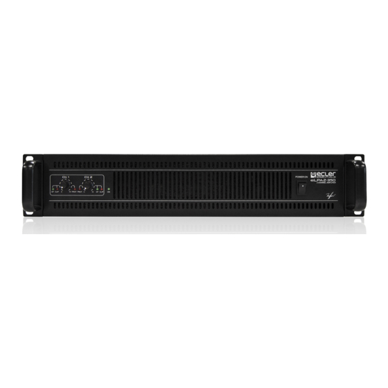
- Seite 1 USER MANUAL MANUAL DE INSTRUCCIONES NOTICE D’EMPLOI BEDIENUNGSANLEITUNG eLPA SERIES eLPA2-350 eLPA2-650 eLPA2-950 eLPA2-1400...
-
Seite 2: Inhaltsverzeichnis
INSTRUCTION MANUAL 1. IMPORTANT NOTE 1.1. Precautions 2. INTRODUCTION 2.1. Main features 3. INSTALLATION 3.1. Placement, mounting, cooling 3.2. Mains connection 3.3. Input signal connections 3.4. Cut filter or crossover 3.5. Limiter circuit 3.6. Output connections 4. OPERATION AND USAGE 4.1. -
Seite 3: Important Note
1. IMPORTANT NOTE Congratulations! You are the owner of a carefully designed and manufactured equipment. We thank you for trusting on us and choosing our amplifier eLPA. In order to obtain maximum operability and perfect functioning order, it is most important to carefully read all considerations taken into account in this manual before connecting this amplifier. -
Seite 4: Installation
3.2. Mains connection eLPA2-650, 2-950 and 2-1400 models are powered by alternating current through their universal power supply: 90-264 V and 47 - 63 Hz. eLPA2-350is supplied with alternating current at 230 V, 47 / 63 Hz. All models include fuses to protect against possible overloads. -
Seite 5: Limiter Circuit
3.5. Limiter circuit This provides additional protection and is always activated on amplifiers in the eLPA series. This “ANTICLIP” circuit constantly analyzes the harmonic distortion produced by the excessive clipping of the signal in the amplifier output, and reduces the input level automatically to keep the level of distortion below 0.5% approximately. The clear advantage of a limiting system in front of conventional compressors is that the former does practically not alter the dynamic range, acting only when the distortion threshold is reached. -
Seite 6: Indicators
4.3. Indicators The eLPA amplifiers provide a simple and effective system of indicators: • “PROTECT” indicators (2): They indicate the absence of a power signal in the loudspeaker output of the amplifier. They may be activated for various reasons: 1. In the startup period, from when the power-on button is pressed until the startup time necessary to stabilize the internal voltages of the amplifier has been completed (approximately 10 seconds). - Seite 7 MANUAL DE INSTRUCCIONES 1. NOTA IMPORTANTE 1.1. Precauciones 2. INTRODUCCIÓN 2.1. Prestaciones 3. INSTALACIÓN 3.1. Ubicación, montaje, ventilación 3.2. Conexión a red 3.3. Conexiones de entrada de señal 3.4. Filtro de corte o Crossover 3.5. Circuito limitador 3.6. Conexiones de salida 4.
-
Seite 8: Nota Importante
1. NOTA IMPORTANTE ¡Enhorabuena!. Vd. posee el resultado de un cuidadoso diseño y una esmerada fabricación. Agradecemos su confianza por haber elegido nuestro amplificador eLPA. Para que pueda conseguir la máxima operatividad y un funcionamiento perfecto, antes de su conexión es MUY IMPORTANTE que lea detenidamente las consideraciones que se detallan en éste manual. -
Seite 9: Introducción
2. INTRODUCCIÓN La línea de amplificadores eLPA ofrece la clásica y reconocida fiabilidad profesional de los amplificadores Ecler bajo una nueva estética y a un coste asequible. Está compuesta por 4 modelos estéreo de 350, 650, 950 y 1400 WRMS por canal sobre 4Ω. Todos los modelos ocupan 2 unidades rack de altura y están montados en un robusto chasis. -
Seite 10: Instalación
3.2. Conexión a red Los modelos eLPA2-650, 2-950 y 2-1400 disponen de fuente de alimentación universal, que admite tensión de la red eléctrica de 90 a 264 V, 47 a 63Hz. El modelo eLPA2-350 dispone de fuente de alimentación que admite tensión de la red eléctrica 230 V, 47 a 63 Hz. -
Seite 11: Circuito Limitador
3.5. Circuito limitador Se trata de una protección extra, siempre activa en los amplificadores serie eLPA. Este circuito “ANTICLIP” analiza constantemente la distorsión armónica producida por el recorte excesivo de la señal a la salida del amplificador, reduciendo automáticamente el nivel de entrada para mantener el nivel de distorsión por debajo del 0,5%, aproximadamente. -
Seite 12: Indicadores
4.3. Indicadores Los amplificadores eLPA equipan un simple y eficaz sistema de indicaciones: • Indicadores “PROTECT” (2): Señalan la ausencia de señal de potencia en la salida de altavoces del amplificador. Pueden activarse por diferentes motivos: 1. En el intervalo de puesta en marcha, desde que se pulsa el botón de encendido y hasta que finaliza el tiempo de arranque necesario para la estabilización de las tensiones internas del amplificador (10 segundos aproximadamente). - Seite 13 NOTICE D'EMPLOI 1. NOTE IMPORTANTE 1.1. Précautions 2. INTRODUCTION 2.1. Fonctions 3. INSTALLATION 3.1. Disposition, montage, ventilation 3.2. Connexion au secteur 3.3. Connexions d'entrée de signal 3.4. Filtre séparateur ou Crossover 3.5. Circuit limiteur 3.6. Connexions de sortie 4. FONCTIONNEMENT 4.1.
-
Seite 14: Note Importante
1. NOTE IMPORTANTE Félicitations ! Vous avez en votre possession le résultat d’un design et d’une fabrication particulièrement soignée. Nous vous remercions de la confiance que vous nous portez en choisissant notre amplificateur eLPA. Pour obtenir un bon fonctionnement et des performances maximales, il est important de lire attentivement les instructions ci-dessous avant tout branchement. -
Seite 15: Fonctions
3.2. Connexion au secteur Les modèles eLPA2-650, 2-950 et 2-1400 disposent d’une alimentation universelle qui accepte les tensions électriques de 90 à 264 V, 47/63 Hz. Le modèle eLPA2-350 dispose d’une alimentation qui accepte une tension électrique de 230 V, 47 à... -
Seite 16: Filtre Séparateur Ou Crossover
3.4. Filtre séparateur ou Crossover Le filtre séparateur intégré divise le signal d’entrée en deux bandes de fréquences. En l’activant, le canal 1 reçoit et amplifie la bande de fréquences entre 20 Hz et 150 Hz, alors que le canal 2 le fait avec la bande de fréquences entre 150 Hz et 20 kHz. -
Seite 17: Fonctionnement
4. FONCTIONNEMENT 4.1. Mise en marche. Quand on active l’interrupteur de mise en marche (10), la LED bleue « ON » s’allume ainsi que les deux LED rouges « PROTECT » (2). Environ 10 secondes plus tard, toutes les tensions se sont stabilisées et l’amplificateur est opérationnel, les indicateurs «... - Seite 18 BEDIENUNGSANLEITUNG 1. WICHTIGE VORBEMERKUNG 1.1. Vorsichtsmaßnahmen 2. EINFÜHRUNG 2.1. Wichtigste Merkmale 3. INSTALLATION 3.1. Aufstellung, Einbau, Kühlung 3.2. Netzanschluß 3.3. Anschluß der Signaleingänge 3.4. Cut- oder Crossover-Filter 3.5. Limiterschaltung 3.6. Ausgangsanschlüße 4. INBETRIEBNAHME 4.1. Inbetriebnahme 4.2. Eingangsregler 4.3. Statusanzeigen 5. REINIGUNG 6.
-
Seite 19: Wichtige Vorbemerkung
1. WICHTIGE VORBEMERKUNG Herzlichen Glückwunsch! Sie haben ein hervorragendes Gerät erworben, das mit großer Sorgfalt entwickelt und hergestellt wurde. Wir danken Ihnen für das Vertrauen, das Sie mit der Wahl unseres eLPA in uns gesetzt haben. Um die maximale Leistung und eine zuverlässige Funktion zu erreichen, ist es sehr wichtig, vor dem Anschluß... -
Seite 20: Wichtigste Merkmale
Geräten zu plazieren, sondern möglichst obenauf. 3.2. Netzanschluß Die Modelle eLPA2-650, 2-950 und 2-1400 verfügen über ein universelles Netzteil, das eine Netzspannung von 90 bis 264V, 47 bis 63HZ zulässt. Das Modell eLPA2-350 verfügt über ein Netzteil, das eine Netzspannung von 230V, 47 bis 63 HZ zulässt. -
Seite 21: Cut- Oder Crossover-Filter
3.4. Cut- oder Crossover-Filter Der eingebaute Cut-Filter sorgt für die Teilung des Eingangssignals in zwei Frequenzbandbereiche. Beim Einschalten erhält und verstärkt Kanal 1 den Frequenzbandbereich zwischen 20 Hz und 150 Hz, während Kanal 2 das gleiche für den Frequenzbandbereich zwischen 150 Hz und 20 kHz übernimmt. Die Flankensteigung des Cut- Filters zwischen den beiden Bandbreiten bei 150 Hz beträgt 18 dB / Oktave. -
Seite 22: Inbetriebnahme
4. INBETRIEBNAHME 4.1. Inbetriebnahme Beim Drücken des Einschalters (10) leuchten die blaue LED "ON" sowie die beiden roten LED "PROTECT" (2) auf. Nach etwa 10 Sekunden haben sich alle Spannungen stabilisiert, der Verstärker ist betriebsbereit und die Leuchtanzeigen "PROTECT" erlöschen. In einer kompletten Audio -Installation ist es wichtig, die einzelnen Geräte in folgender Reihenfolge einzuschalten: Signalquellen, Mixer, Equalizer, aktive Filter und schließlich die Endverstärker. -
Seite 23: Diagramme
6. DIAGRAMS 6. DIAGRAMAS 6. SCHÉMAS 6. DIAGRAMME 6.1. Technical characteristics 6.1. Características técnicas 6.1. Caractéristiques techniques 6.1. Technische daten POWER 20-20kHz 1% THD 2-350 2-650 2-950 2-1400__ 1 Channel @ 4Ω 345 WRMS 630 WRMS 950 WRMS 1400 WRMS 1 Channel @ 8Ω... -
Seite 24: Function List
6.2. Function list 6.2. Lista de funciones 1. Signal present indicator, SIGNAL 1. Indicador de presencia de señal en la entrada, SIGNAL 2. Clip indicator, CLIP 2. Indicador de recorte, CLIP 3. Input attenuator 3. Atenuador de entrada 4. Protection indicator, PROTECT 4. -
Seite 25: Funktionsübersicht
6.3. Function diagram 6.3. Diagrama de funciones 6.3. Schéma de fonctionnement 6.3. Funktionsübersicht... - Seite 26 NEEC AUDIO BARCELONA S.L. Motors 166-168, 08038 Barcelona, Spain www.ecler.com - information@ecler.es 50.0316.01.02...