Herunterladen Inhalt Inhalt Diese Seite drucken

Werbung

Verfügbare Sprachen
  • DE

Verfügbare Sprachen

  • DEUTSCH, seite 28
High Quality Nautical Equipment
RDS
RDS 1541
IT
Manuale di installazione ed uso
GB
Manual for use and installation
FR
Mode d'emploi et d'installation
DE
Installations- und Benutzerhandbuch
ES
Manual de instalación y uso
REMOTE DISPLAY
PANNELLO REMOTO RDS 1541
REMOTE DISPLAY RDS 1541
TABLEAU À DISTANCE RDS 1541
FERNBEDIENUNGSTAFEL RDS 1541
PANEL REMOTO RDS 1541
REV 001
A

Werbung

Inhaltsverzeichnis
loading

Inhaltszusammenfassung für Quick RDS 1541

  • Seite 1 RDS 1541 PANNELLO REMOTO RDS 1541 Manuale di installazione ed uso REMOTE DISPLAY RDS 1541 Manual for use and installation TABLEAU À DISTANCE RDS 1541 Mode d’emploi et d’installation FERNBEDIENUNGSTAFEL RDS 1541 Installations- und Benutzerhandbuch PANEL REMOTO RDS 1541 Manual de instalación y uso...
  • Seite 3 Pág. 39 INSTALACIÓN - FUNCIONAMIENTO: activación de los terminales Pág. 40 FUNCIONAMIENTO: configuración del instrumento Pág. 41 FUNCIONAMIENTO - SEÑALACIONES: Pág. 42 GESTIÓN DE PROBLEMAS: señalización de problemas - gestión de problemas del instrumento Pág. 43 ESPECIFICACIONES TÉCNICAS RDS 1541 - REV0001A...
  • Seite 4: Caratteristiche E Installazione

    CARATTERISTICHE E INSTALLAZIONE RDS 1541 Il pannello remoto RDS 1541 è uno strumento che permette di monitorare lo stato dei caricabatterie Quick serie SBC NRG, tramite l'interfaccia CAN BUS. Gli importanti vantaggi che l'RDS 1541 offre sono: • Display LCD alfanumerico.
  • Seite 5 • Realizzare l'asola per il passaggio della parte posteriore dello strumento. • Rimuovere la dima ed eventuali bave presenti. • Inserire lo strumento nella sede. • Fissare lo strumento al pannello avvitando le viti (non in dotazione). RDS 1541 - REV001A...
  • Seite 6: Collegamento Elettrico

    CANH CANL Interfaccia CAN SCHEMA DI COLLEGAMENTO FIG.1 TERMINAZIONE ATTIVATA SBC NRG CAN IN 1 2 3 4 5 6 CAN IN CAN OUT CONNETTORE TERMINAZIONE CAN OUT RDS 1541 BATTERIA 12V / 24V FUSIBILE INTERRUTTORE RDS 1541 - REV001A...
  • Seite 7 DIP-SWITCH TERMINAZIONE ATTIVATA 1 2 3 4 5 6 RDS 1541 ATTIVAZIONE DEI TERMINATORI Attivare la terminazione sul primo e sull'ultimo dispositivo collegato alla rete. Per attivare la terminazione sullo strumento, vedere paragrafo CONFIGURAZIONE DELLO STRUMENTO. RDS 1541 - REV001A...
  • Seite 8: Configurazione Dello Strumento

    1 2 3 4 Visualizzazione tensione MASTER, SLAVE 2 1 2 3 4 Visualizzazione tensione MASTER, SLAVE 1 / 2 1 2 3 4 IMPOSTAZIONE DI FABBRICA: GRUPPO PRIORITÀ TERMINATORE CAN DISATTIVATO Intensità retro-illuminazione BASSA Visualizzazione tensione MASTER RDS 1541 - REV001A...
  • Seite 9: Funzionamento Dello Strumento

    Corrente totale erogata dal carica batteria. Indicazione dello stato del sistema STATUS (stato di carica, stato generico, messaggi di avvertimento o problemi con reset automatico). Questo simbolo indica la presenza di più messaggi nel campo Status. RDS 1541 - REV001A...
  • Seite 10 Configurazione errata dip-switch Nel caso in cui l’utente imposti in maniera errata i dip-switch compare la seguente segnalazione: Modello caricabatterie non riconoscito Nel caso in cui lo strumento non riconosca il modello di caricabatteria compare la seguente segnalazione: RDS 1541 - REV001A...
  • Seite 11: Dati Tecnici

    (3) Con temperature inferiori a 0°C i cristalli del display rallentano il loro movimento. ® QUICK SI RISERVA IL DIRITTO DI APPORTARE MODIFICHE ALLE CARATTERISTICHE TECNICHE DELL'APPARECCHIO E AL CONTENUTO DI QUESTO MANUALE SENZA ALCUN PREAVVISO. RDS 1541 - REV001A...
  • Seite 12 CHARACTERISTICS AND INSTALLATION RDS 1541 The RDS 1541 remote display allows status of the Quick battery chargers series SBC NRG to be monitored through the CAN BUS interface. The important advantages which the RDS 1541 offer, are: • Alphanumeric LCD display.
  • Seite 13: Panel Installation

    • Create the slot for the passage of the rear part of the instrument. • Remove the template and any burrs present. • Put the instrument in place. • Fix the instrument to the panel with the screws (not included in the equipment). RDS 1541 - REV001A...
  • Seite 14: Electric Connections

    CAN interface CANH CANL CAN interface CONNECTION DIAGRAM FIG.1 TERMINATION ACTIVATED SBC NRG CAN IN 1 2 3 4 5 6 CAN IN CAN OUT TERMINATION CONNECTOR CAN OUT RDS 1541 BATTERY 12V / 24V FUSE SWITCH RDS 1541 - REV001A...
  • Seite 15 TERMINATION ACTIVATED 1 2 3 4 5 6 RDS 1541 ACTIVATING THE TERMINATORS Activate the termination at the first and last device connected to the network. To activate the termination, see paragraph SETTING UP THE INSTRUMENT. RDS 1541 - REV001A...
  • Seite 16: Setting Up The Instrument

    1 2 3 4 Voltage display MASTER, SLAVE 2 1 2 3 4 Voltage display MASTER, SLAVE 1 / 2 1 2 3 4 FACTORY SETTING: GROUP PRIORITY CAN TERMINATOR DEACTIVATED Backlighting Intensity LOW Voltage display MASTER RDS 1541 - REV001A...
  • Seite 17: Instrument Operation

    SLAVE 2 output voltage. IT OUT Battery charger total output current. Indication of system status STATUS (charging status, generic status, warning messages or problems with automatic reset). This symbol indicates the presence of multiple messages in the Status field. RDS 1541 - REV001A...
  • Seite 18 The following will appear if there is a problem with the flash memory checksum: Dip-switch incorrect configuration The following will appear if the user incorrectly sets the dip-switches: Battery charger model not recognised The following will appear if the instrument does not recognise the battery charger model: RDS 1541 - REV001A...
  • Seite 19: Technical Data

    (2) Typical value with backlighting on at high intensity. (3) At temperatures below 0°C the movement of the display crystals slows down. ® QUICK RESERVES THE RIGHT TO MODIFY THE TECHNICAL CHARACTERISTICS OF THE EQUIPMENT AND THE CONTENTS OF THIS MANUAL WITHOUT PRIOR NOTICE. RDS 1541 - REV001A...
  • Seite 20: Installation De L'instrument

    CARACTERISTIQUES ET INSTALLATION RDS 1541 Le tableau déporté RDS 1541 est un instrument qui permet de contrôler l'état de charge de batterie Quick série SBC NRG, par l'intermédiaire de l'interface CAN BUS. Autres avantages du RDS 1541 sont: • Ecran LCD alphanumérique.
  • Seite 21 • Réaliser découpe pour le passage de la partie arrière de l'instrument. • Retirer le gabarit et les éventuelles ébarbures présentes. • Introduire l'instrument dans son logement. • Fixer l'instrument au panneau a l'aide des vis (non fournies avec l'appareil). RDS 1541 - REV001A...
  • Seite 22: Branchement Electrique

    CANL Interface CAN SCHEMA DE CONNEXION FIG.1 TERMINAISON ACTIVÉE SBC NRG CAN IN 1 2 3 4 5 6 CAN IN CAN OUT CONNECTEUR DE TERMINAISON CAN OUT RDS 1541 BATTERIE 12V / 24V FUSIBLE INTERRUPTEUR RDS 1541 - REV001A...
  • Seite 23 1 2 3 4 5 6 RDS 1541 ACTIVATION DES TERMINAUX Activer la terminaison sur le premier et sur le dernier dispositif relié au réseau. Pour activer la terminaison sur l'instrument, voir paragraphe CONFIGURATION DE L'INSTRUMENT. RDS 1541 - REV001A...
  • Seite 24: Configuration De L'instrument

    1 2 3 4 Affichage tension MASTER, SLAVE 2 1 2 3 4 Affichage tension MASTER, SLAVE 1 / 2 1 2 3 4 PARAMETRAGE D'USINE: GROUPE PRIORITE TERMINAL CAN DESACTIVE Intensité BASSE de rétro-illumination Affichage tension MASTER RDS 1541 - REV001A...
  • Seite 25: Fonctionnement De L'instrument

    Courant total distribué par le chargeur de batteries. Indication de l'état du système STATUS (état de charge, état général, messages d'avertissement ou problèmes avec réinitialisation automatique). Ce symbole indique la présence de plusieurs messages dans Status. RDS 1541 - REV001A...
  • Seite 26 Configuration erronée dip-switch Si l'utilisateur configure de façon incorrecte les dip-switch le signal suivant apparaît: Modèle de chargeur de batterie non identifié Si l'instrument ne reconnaît pas le modèle de chargeur de batterie le signal suivant apparaît: RDS 1541 - REV001A...
  • Seite 27: Caracteristiques Techniques

    SE RÉ SER VE LE DRO IT D'AP POR TER LES MO DI FI CA TIONS NÉ CES SA I RES A UX CA RAC TÉ RIS TI QUES TE CHNI QUES DE L'AP PA RE IL ET AU CON TE NU DE CE LI VRET SANS A VIS PRÉ A LA BLE. RDS 1541 - REV001A...
  • Seite 28: Eigenschaften Und Installation

    EIGENSCHAFTEN UND INSTALLATION RDS 1541 Beim Überwachungspaneel RDS 1541 handelt es sich um ein Gerät zur Überwachung des Zustands der Batterieladegeräte Quick Serie SBC NRG anhand der CAN BUS-Schnittstelle. Die Überwachungspaneel RDS 1541 bieten die folgenden Vorteile: • Alphanumerische LCD-Display.
  • Seite 29: Installation An Der Schalttafel

    • Einen Schlitz ausführen, durch den die Rückseite vom Instrument gesteckt wird. • Die Schablone sowie eventuelle an den Bohrungen vorhandene Grate entfernen. • Das Gerät einsetzen. • Das Instrument an der Tafel befestigen und die Schrauben anziehen (nicht mitgelieferten). RDS 1541 - REV001A...
  • Seite 30: Stromanschluss

    Schnittstelle CAN CANH Schnittstelle CAN CANL ANSCHLUSSPLAN ABB. 1 ABSCHLUSS AKTIVIERT SBC NRG CAN IN 1 2 3 4 5 6 CAN IN CAN OUT CONNETTORE TERMINAZIONE CAN OUT RDS 1541 BATTERIE 12V / 24V SICHERUNG SCHALTER RDS 1541 - REV001A...
  • Seite 31: Installation - Betrieb

    1 2 3 4 5 6 RDS 1541 AKTIVIERUNG DER ABSCHLUSSWIDERSTÄNDE Den Abschluss an der ersten und an der letzten am Netz angeschlossenen Vorrichtung aktivieren. Um den Abschluss des Gerätes zu aktivieren, siehe Abschnitt KONFIGURATION DES GERÄTES. RDS 1541 - REV001A...
  • Seite 32: Betrieb

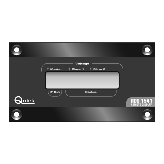
    Spannungsanzeige MASTER, SLAVE 1 1 2 3 4 Spannungsanzeige MASTER, SLAVE 2 1 2 3 4 Spannungsanzeige MASTER, SLAVE 1 / 2 1 2 3 4 WERKEINSTELLUNG: GRUPPE PRIORITÄT ABSCHLUSSWIDERSTAND CAN DEAKTIVIERT SCHWACHE Hintergrundsbeleuchtung Spannungsanzeige MASTER RDS 1541 - REV001A...
  • Seite 33: Betrieb - Meldungen

    Ausgangsspannung SLAVE 1. SLAVE 2 Ausgangsspannung SLAVE 2. IT OUT Insgesamt vom Batterieladegerät ausgegebener Strom. Anzeige des Systemzustands STATUS (Ladezustand, Normalzustand, Warnhinweise oder Probleme mit dem automatischen Reset). Dieses Symbol zeigt das Vorhandensein mehrerer Meldungen im Camo-Zustand an. RDS 1541 - REV001A...
  • Seite 34: Problemverwaltung

    Wenn ein Problem mit der Checksum des Flashspeichers auftritt, erscheint folgende Anzeige: Fehlerhafte Konfigurierung des Dip-Schalters Falls der Anwender die Dip-Schalter falsch eingibt, erscheint folgende Anzeige: Ladegerätmodell nicht erkannt Falls das Instrument das Ladegerät nicht erkennt, erscheint folgende Anzeige: RDS 1541 - REV001A...
  • Seite 35: Technische Daten

    BE HÄLT SICH DAS RECHT AUF ÄN DE RUN GEN DER TECH NI SCHEN EI GEN SCHAF TEN DES GERÄTES UND DES IN HALTS DIE SES HAND BUCHS OH NE VO RAN KÜN DI GUNG VOR. RDS 1541 - REV001A...
  • Seite 36: Instalación Del Instrumento

    CARACTERISTÍCAS E INSTALACIÓN RDS 1541 El panel remoto RDS 1541 es un instrumento que permite el monitoreo del estado de los cargadores de baterías Quick serie SBC NRG, trámite la interfaz CAN BUS. Otras ventajas que puede ofrecer el panel remoto RDS 1541 son: •...
  • Seite 37 • Realizar el ojal para el pasaje de la parte posterior del instrumento. • Quitar la plantilla y eventuales babas presentes en los agujeros. • Introducir el instrumento en su alojamiento. • Fijar el instrumento al panel atornillando los tornillos (no suministrados). RDS 1541 - REV001A...
  • Seite 38: Conexión Eléctrica

    CANH Interfaz CAN CANL ESQUEMA DE CONEXIÓN FIG.1 TERMINACIÓN ACTIVADA SBC NRG CAN IN 1 2 3 4 5 6 CAN IN CAN OUT CONECTOR TERMINACIÓN CAN OUT RDS 1541 BATERÍA 12V / 24V FUSIBLE INTERRUPTOR RDS 1541 - REV001A...
  • Seite 39 1 2 3 4 5 6 RDS 1541 ACTIVACIÓN DE LOS TERMINALES Activar la terminación en el primero y en el último dispositivo conectado en la red. Para activar la terminación sobre el instrumento, ver el parágrafo CONFIGURACIÓN DEL INSTRUMENTO. RDS 1541 - REV001A...
  • Seite 40: Configuración Del Instrumento

    1 2 3 4 Visualización tensión MASTER, SLAVE 2 1 2 3 4 Visualización tensión MASTER, SLAVE 1 / 2 1 2 3 4 CONFIGURACIÓN DE FABRICA: GRUPO PRIORIDAD TERMINAL CAN DISATTIVATO Intensidad retro-illuminación BAJA Visualización tensión MASTER RDS 1541 - REV001A...
  • Seite 41 Corriente total distribuida por el cargador de baterías. Indicación del estado del sistema STATUS (estado de carga, estado genético, mensajes de advertencia o problemas con el reset automático). Este símbolo indica la presencia de más mensajes en el campo Status. RDS 1541 - REV001A...
  • Seite 42 Configuración incorrecta de dip-switch Si el usuario configura de manera incorrecta los dip-switch aparece la siguiente señalización: Modelo de cargador de baterías no reconocido Si el instrumento no reconocer el modelo de cargador de baterías aparece la siguiente señalización: RDS 1541 - REV001A...
  • Seite 43: Especificaciones Técnicas

    SE RE SER VA EL DE RE CHO DE A POR TAR MO DI FI CA CIO NES EN LAS CA RAC TE RÍS TI CAS TÉC NI CAS DEL A PA RA TO Y EN EL CON TE NI DO DE ES TE MA NUAL SIN O BLI GA CIÓN DE A VI SAR PRE VIA MEN TE. RDS 1541 - REV001A...
  • Seite 44 RDS 1541 DIMENSIONI (mm) DIMENSIONS - DIMENSIONS - ABMESSUNGEN - DIMENSIONES RDS 1541 - REV001A...
  • Seite 45 NOTES...
  • Seite 46 NOTES...
  • Seite 48: Remote Display

    Code et numéro de série du produit Code- und Seriennummer des Produkts Código y número de serie del producto ® QUICK S.p.A. - Via Piangipane, 120/A - 48124 Piangipane (RAVENNA) - ITALY Tel. +39.0544.415061 - Fax +39.0544.415047 www.quickitaly.com - E-mail: quick@quickitaly.com...

Inhaltsverzeichnis