Herunterladen Inhalt Inhalt Diese Seite drucken

+GF+ PA30 Bedienungsanleitung

Pneumatischer stellantrieb
Inhaltsverzeichnis

Werbung

Verfügbare Sprachen

Verfügbare Sprachen

GF Piping Systems
Bedienungsanleitung
Instruction Manual
Instruction de service
Instrucciones para la Operación
Pneumatischer Stellantrieb PA30 – PA90
Pneumatic actuator PA30 – PA90
Servomécanisme pneumatique Type PA30 - PA90
Actuadores neumáticos Tipo PA30 - PA90

Werbung

Inhaltsverzeichnis
loading

Inhaltszusammenfassung für +GF+ PA30

  • Seite 1 GF Piping Systems Bedienungsanleitung Instruction Manual Instruction de service Instrucciones para la Operación Pneumatischer Stellantrieb PA30 – PA90 Pneumatic actuator PA30 – PA90 Servomécanisme pneumatique Type PA30 - PA90 Actuadores neumáticos Tipo PA30 - PA90...
  • Seite 3 Deutsch Pneumatischer Stellantrieb Typ PA30 – PA90 ..….…………………... 4 English Pneumatic actuator unit Type PA30 – PA90 ……………..……………. 29 Français Servomécanisme pneumatique Type PA30 – PA90 ………………... 54 Español Actuadores neumáticos del tipo PA30 – PA90 ………………………….. 79...
  • Seite 4: Originalbetriebsanleitung

    Betriebsanleitung Originalbetriebsanleitung Betriebsanleitung befolgen Die Betriebsanleitung ist Teil des Produkts und ein wichtiger Baustein im Sicherheitskonzept.  Betriebsanleitung lesen und befolgen.  Betriebsanleitung stets am Produkt verfügbar halten.  Betriebsanleitung an alle nachfolgenden Verwender des Produkts weitergeben.
  • Seite 5: Inhaltsverzeichnis

    Betriebsanleitung Inhaltsverzeichnis Inhaltsverzeichnis Originalbetriebsanleitung ....................... 4 Inhaltsverzeichnis ..........................5 Bestimmungsgemässe Verwendung ..................6 Zu diesem Dokument ......................7 Warnhinweise ........................7 Mitgeltende Dokumente ......................7 Beschriebene Typen und Funktionen ................... 8 Abkürzungen und Begriffe ....................8 Sicherheit und Verantwortung ....................9 Sicherheitshinweise ......................
  • Seite 6: Bestimmungsgemässe Verwendung

    Bestimmungsgemässe Verwendung Die nachfolgenden Beschreibungen und Anweisungen gelten für die pneumatischen Stellantriebe vom Typ PA30 – PA90 mit Funktion DA, FC und FO. Diese Stellantriebe betätigen Ventile mit einem Schwenkbereich von 90° über die F04/05-Schnittstelle bis zu einem Antriebsmoment von maximal 3840 Nm und werden durch Steuerluft (3 –...
  • Seite 7: Zu Diesem Dokument

    Betriebsanleitung Zu diesem Dokument Zu diesem Dokument Dieses Dokument beinhaltet alle notwendigen Informationen um das Produkt zu montieren, in Betrieb zu nehmen, zu betreiben und zu warten. Warnhinweise In dieser Anleitung werden Warnhinweise verwendet, um Sie vor Tod, Verletzungen oder vor Sachschäden zu warnen.
  • Seite 8: Beschriebene Typen Und Funktionen

    Zu diesem Dokument Betriebsanleitung Beschriebene Typen und Funktionen Pneumatischer Stellantrieb FC/FO Code-Nr. Code-Nr. Code-Nr. PA30 198 800 757 198 800 737 198 811 025 PA35 198 800 037 198 800 758 198 811 026 PA40 198 800 728 198 800 759...
  • Seite 9: Sicherheit Und Verantwortung

    Betriebsanleitung Sicherheit und Verantwortung Sicherheit und Verantwortung Sicherheitshinweise WARNUNG Verletzungsgefahr beim Zerlegen des Produkts! Pneumatische Stellantriebe des Typs FC und FO besitzen vorgespannte Federn zur automatischen Rückstellung in die Sicherheitsstellung.  Das Zerlegen dieser Antriebe ist gefährlich, es darf vom Kunden nicht durchgeführt werden.
  • Seite 10: Transport Und Lagerung

    Transport und Lagerung Betriebsanleitung Transport und Lagerung Das Produkt muss sorgfältig behandelt, transportiert und gelagert werden. Hierzu sind folgende Punkte zu beachten:  Produkt beim Transport gegen äussere Gewalt (Stoss, Schlag, Vibrationen etc.) schützen.  Produkt in ungeöffneter Originalverpackung transportieren und/oder lagern. ...
  • Seite 11: Aufbau Und Funktion

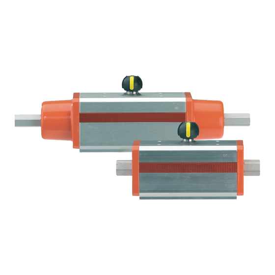
    Betriebsanleitung Aufbau und Funktion Aufbau und Funktion Federdeckel Schnittstelle nach ISO 5211 Hubbegrenzungsschraube Steuerluftanschluss Kolben Kontermutter Stellungsanzeige Der pneumatische Stellantrieb setzt sich aus den folgenden Bauteilen zusammen:  Gehäuse mit aufgeschraubtem Federdeckel (1), Stellungsanzeige (4), Steuerluftanschluss (D) und Zubehörschnittstelle (5) nach ISO 5211 ...
  • Seite 12: Funktionen

    Aufbau und Funktion Betriebsanleitung Funktionen Funktion FC: Federkraft schliessend Steuerluft über 3/2-Wegeventil am Anschluss A dreht den Antrieb 90° nach links Funktion FO: Federkraft öffnend Steuerluft über 3/2-Wegeventil am Anschluss A dreht den Antrieb 90° nach rechts Funktion DA: Doppelt wirkend Steuerluft über 5/2-Wegeventil am Anschluss A dreht den Antrieb 90°...
  • Seite 13: Hubbegrenzung

    Betriebsanleitung Aufbau und Funktion Hubbegrenzung Bei Ausführungen mit Hubbegrenzung ist die Hubbegrenzung ab Werk auf 90° eingestellt. Diese Einstellung kann bei Bedarf verändert werden. Eine Begrenzung der Drehbewegung in Richtung Arbeitsposition auf weniger als 90°, z. B. auf 45°, ist auf diese Weise möglich. HINWEIS Bei Ausführungen mit Funktion DA ist nur eine Begrenzung in Öffnungsrichtung möglich.
  • Seite 14: Einstellen Der Zu-Stellung Bei Den Gf Absperrklappen Typ 036 Und Typ 037

    Aufbau und Funktion Betriebsanleitung 5. Stellantrieb in Ruhestellung bringen (Funktion DA: Stellung AUF) 6. Stellwinkel prüfen und, falls notwendig, Prozedur ab Punkt 3 wiederholen. 7. Spezialmutter (2) wieder einschrauben und O-Ring-Dichtungen in die entsprechenden Sitze (4) eindrücken. ∢ ∢ Hubbegrenzung der Drehung nach links, max. 10° , 90 –...
  • Seite 15: Identifikation

    Betriebsanleitung Aufbau und Funktion Identifikation Bestellnummer Schutzklasse Seriennummer Max. Steuerdruck Funktion Stellungsanzeige Die Stellungsanzeige zeigt die Ventilposition an. Die Ventilpositionen können am montierten Deckel abgelesen werden. Position ZU Position AUF Die Ventilpositionen können an der Markierung (2) der Stellungsanzeige (1) abgelesen werden. Die Zubehörschnittstelle nach NAMUR (3) dient zur Anbringung von Zubehör, wie z.
  • Seite 16: Technische Daten

    Technische Daten Betriebsanleitung Technische Daten Als Referenz siehe auch Planungsgrundlagen, verfügbar zum Download unter http://www.gfps.com >> Support and Services >> Planning Assistance >> Planning Fundamentals >> Planning Fundamentals Industry Daten Wert Steuermedium Druckluft Druckluftklasse nach 2 oder 3 bei -10 °C, ISO 8573-1 3 oder 4 bei T >...
  • Seite 17: Drehmomentcharakteristik

    Grösse 5.6 bar 5.6 bar 5.6 bar 5.6 bar 5.6 bar Luft Feder Luft Feder 0° 30.0 0° 30.0 20.0 0° 25.0 PA30 45° 15.0 50° 15.0 15.0 50° 15.0 90° 22.5 90° 20.0 30.0 90° 22.5 0° 45.0 0°...
  • Seite 18 Technische Daten Betriebsanleitung Doppelt wirkend Federkraft schliessend / Federkraft öffnend * Federkraft öffnend 0° 180.0 0° 180.0 120.0 0° 150.0 PA55 45° 90.0 50° 90.0 90.0 50° 90.0 90° 135.0 90° 120.0 180.0 90° 135.0 0° 240.0 0° 180.0 160.0 0°...
  • Seite 19: Baumasse

    Betriebsanleitung Technische Daten Baumasse...
  • Seite 20 Technische Daten Betriebsanleitung Einfachwirkend (FC/FO) Schnitt stelle [mm] [mm] [mm] [mm] [mm] [mm] [mm] PA30 F03/05 36/50 M5/M6 1/8“ PA35 F05/07 50/70 M6/M8 1/8“ PA40 F05/07 50/70 M6/M8 1/8“ PA45 F05/07 50/70 M6/M8 1/8“ PA50 F05/07 50/70 M6/M8 1/8“ PA55...
  • Seite 21 Betriebsanleitung Technische Daten Doppeltwirkend (DA) Schnitt stelle [mm] [mm] [mm] [mm] [mm] [mm] [mm] PA30 F03/05 M5/6 1/8“ PA35 F03/05 M5/6 1/8“ PA40 F03/05 M5/6 1/8“ PA45 F05/07 M6/8 1/8“ PA50 F05/07 M6/8 1/8“ PA55 F05/07 M6/8 1/8“ PA60 F05/07 M6/8 1/8“...
  • Seite 22: Installation

    Installation Betriebsanleitung Installation Die Antriebe verfügen über eine nach ISO 5211 standardisierte Schnittstelle. 7.1.1 Einfachwirkend (FC/FO) Schnittstelle PA30 F03/05 PA35 PA40 F05/07 PA45 PA50 PA55 F07/10 PA60 PA65 F010/12 PA70 PA75 PA80 7.1.2 Doppeltwirkend (DA) Schnittstelle PA30 PA35 F03/05 PA40...
  • Seite 23: Steuerluft

    Betriebsanleitung Inbetriebnahme Steuerluft HINWEIS Be- und Entlüftungsöffnung nicht verstopfen! Bei Ausführungen mit Funktion FC/FO darf die mit 1 transparenten Stopfen geschützte Entlüftungsöffnung (1) nicht beschädigt oder verstopft werden, da sonst die Bewegung des Antriebs gehemmt wird. Die Steuerluftanschlüsse sind mit Aufklebern (2) versehen, die die Wirkung der Steuerluft am jeweiligen Anschluss bezeichnen.
  • Seite 24: Wartung

    Wartung Betriebsanleitung Wartung VORSICHT Verletzungsgefahr und fehlende Produktqualität durch Verwendung von Ersatzteilen, die nicht von GF Piping Systems zur Verfügung gestellt wurden! Verletzungsgefahr und Sachschaden möglich.  Verwenden Sie ausschliesslich Originalteile. Wartungsplan  Wartungsintervalle entsprechend der Einsatzbedingungen festlegen (z. B. Stellzyklen, Medium, Umgebungstemperatur).
  • Seite 25: Störungsbehebung

    Betriebsanleitung Störungsbehebung Störungsbehebung Störung Mögliche Ursache Störungsbehebung Höhe des Steuerdrucks nicht  Steuerdruck überprüfen korrekt gewählt Funktion und Anschlüsse für  Funktion FC, FO, DA und Steuerluft passen nicht zugehörige Anschlüsse zusammen überprüfen Armatur übt nicht die Steuerluft ist ausgefallen ...
  • Seite 26: Zubehör

    Zubehör Betriebsanleitung Zubehör 11.1 Zubehör steuerluftseitig (Details siehe www.gfps.com) Bezeichnung Kabellänge Code-Nr. Ventilinsel Typ PV2000 5/2-Vorsteuer-Magnetventil zur Batteriemontage – 199 190 423 2 x 3/2-Vorsteuer-Magnetventil zur Batteriemontage – 199 190 422 Anschlussmodul mit D-Sub-Stecker – 199 190 424 Endmodul – 199 190 426 D-Sub-Stecker, 25-polig, mit Anschlusskabel 25 x 0,34 mm 1,5 m...
  • Seite 27: Entsorgung

    Betriebsanleitung Entsorgung Entsorgung  Vor Entsorgung die einzelnen Materialien nach recycelbaren Stoffen, Normalabfall und Sonderabfall trennen.  Bei Entsorgung oder Recycling des Produkts, der einzelnen Komponenten und der Verpackung die örtlichen gesetzlichen Bestimmungen und Verordnungen einhalten.  Länderspezifische Vorschriften, Normen und Richtlinien beachten. VORSICHT Teile des Produkts können mit gesundheits- und umweltschädlichen Medien kontaminiert sein, so dass eine einfache Reinigung nicht ausreichend ist!
  • Seite 28: Hersteller

    Georg Fischer Piping Systems Ltd. Ebnatstrasse 111 8201 Schaffhausen / Switzerland Hiermit bestätigen wir, dass die unvollständige Maschine: Pneumatischer Schwenkantrieb Typ: PA30 – PA90 Funktionen: Failsafe Close (FC); Failsafe Open (FO); Double Acting (DA) Code: 198.800.xxx | 198.811.xxx mit den einschlägigen Bestimmungen der Maschinenrichtlinie 2006/42/EG konform ist.
  • Seite 29: Original Instruction Manual

    Instruction manual Original instruction manual Original instruction manual Follow the instruction manual The instruction manual is part of the product and is an important element of the safety concept.  Read and follow the instruction manual.  Always keep the instruction manual available at the product. ...
  • Seite 30: Contents

    Instruction manual Contents Original instruction manual ......................29 Contents ............................30 Intended use .........................31 About this document ......................32 Warnings ..........................32 Other related documents .....................32 Types and functions described ....................33 Terms and abbreviations ......................33 Safety and responsibility ......................34 Safety information ........................34 Transport and storage ......................35 Design and function ......................36 Functions ..........................37 Stroke limiter ........................38...
  • Seite 31: Intended Use

    Intended use Instruction manual Intended use The following descriptions and instructions apply to pneumatic actuators Type PA30 – PA90 with DA, FC and FO function. These actuators actuate valves with a pivoting range of 90° through a F04/05 interface with a maximum actuating torque of 3840 Nm, and are operated by control air (3 –...
  • Seite 32: About This Document

    About this document Instruction manual About this document This document contains all the information necessary for installation, operation and maintenance of the product. Warnings This instruction manual contains warning signs that indicate a risk of death, injury, or material damage. Always read and pay attention to these warnings! WARNING WARNUNG Danger to life or risk of serious physical injury!
  • Seite 33: Types And Functions Described

    Instruction manual About this document Types and functions described Pneumatic actuator FC/FO Code No. Code No. Code No. PA30 198 800 757 198 800 737 198 811 025 PA35 198 800 037 198 800 758 198 811 026 PA40 198 800 728...
  • Seite 34: Safety And Responsibility

    Safety and responsibility Instruction manual Safety and responsibility Safety information WARNING WARNUNG Risk of injury if disassembling the product! Pneumatic actuators of the FC and FO type contain pre-loaded springs which automatically return the actuator to the fail-safe position.  Disassembling these actuators is dangerous and should not be carried out by the customer.
  • Seite 35: Transport And Storage

    Instruction manual Transport and storage Transport and storage The product must be handled, transported, and stored with care. For this purpose, pay attention to the following points:  Protect the product against external forces during transport (impacts, knocks, vibrations etc.). ...
  • Seite 36: Design And Function

    Design and function Instruction manual Design and function Spring cover Interface as defined in ISO 5211 Stroke limit screw Control air connection Piston Locking nut Position indicator The pneumatic actuator is made up of the following components:  Housing with screw-on spring cover (1), position indicator (4), control air connection (D) and standard accessory interface (5) as defined in ISO 5211 ...
  • Seite 37: Functions

    Instruction manual Design and function Functions FC function: spring closed Control air through a 3/2-way valve on connection A turns the actuator 90° to the left FO function: spring opened Control air through a 3/2-way valve on connection A turns the actuator 90° to the right.
  • Seite 38: Stroke Limiter

    Design and function Instruction manual Stroke limiter In versions with the stroke limiter, stroke limiting is set to 90° ex works. This setting can be changed if required. This allows the turning movement towards working position to be limited to less than 90°, e.g. 45°. NOTE HINWEIS In versions with the DA function, limiting is possible only towards the open position.
  • Seite 39: Settings For The Closed Position For Butterfly Valves Type 036 And Type 037

    Instruction manual Design and function 5. Bring the actuator to rest position (DA function: OPEN position) 6. Check the actuating angle and repeat the procedure starting from Point 3 if necessary. 7. Screw in the special nut again (2) and press the O-ring seals into the corresponding seats (4).
  • Seite 40: Identification

    Design and function Instruction manual Identification Order number Type Protection class Serial number Max. operating pressure Function Position indicator The position indicator shows the valve position. The valve positions can be read on the fitted cover. CLOSED position OPEN position Valve positions can be read off at the mark (2) on the position indicator (1).
  • Seite 41: Technical Specifications

    Instruction manual Technical specifications Technical specifications For reference, please see the Planning Fundamentals which are available for download at http://www.gfps.com >> Support and Services >> Planning Assistance >> Planning Fundamentals >> Planning Fundamentals Industry Data Kv value Control medium Compressed air Compressed air class as 2 or 3 at -10 °C, defined in ISO 8573-1...
  • Seite 42: Torque Characteristic Curves

    ° ° Size 5.6 bar 5.6 bar 5.6 bar 5.6 bar 5.6 bar Spring Spring 0° 30.0 0° 30.0 20.0 0° 25.0 PA30 45° 15.0 50° 15.0 15.0 50° 15.0 90° 22.5 90° 20.0 30.0 90° 22.5 0° 45.0 0°...
  • Seite 43 Instruction manual Technical specifications Double-acting Spring closed / Spring opened * spring opened 0° 180.0 0° 180.0 120.0 0° 150.0 PA55 45° 90.0 50° 90.0 90.0 50° 90.0 90° 135.0 90° 120.0 180.0 90° 135.0 0° 240.0 0° 180.0 160.0 0°...
  • Seite 44: Dimensions

    Technical specifications Instruction manual Dimensions...
  • Seite 45 Instruction manual Technical specifications Single-acting (FC/FO) Type Inter- face [mm] [mm] [mm] [mm] [mm] [mm] [mm] PA30 F03/05 36/50 M5/M6 1/8“ PA35 F05/07 50/70 M6/M8 1/8“ PA40 F05/07 50/70 M6/M8 1/8“ PA45 F05/07 50/70 M6/M8 1/8“ PA50 F05/07 50/70 M6/M8 1/8“...
  • Seite 46 Technical specifications Instruction manual Double-acting (DA) Type Inter- face [mm] [mm] [mm] [mm] [mm] [mm] [mm] PA30 F03/05 M5/6 1/8“ PA35 F03/05 M5/6 1/8“ PA40 F03/05 M5/6 1/8“ PA45 F05/07 M6/8 1/8“ PA50 F05/07 M6/8 1/8“ PA55 F05/07 M6/8 1/8“...
  • Seite 47: Installation

    Instruction manual Installation Installation The actuators have a standard interface as defined in ISO 5211. 7.1.1 Single-acting (FC/FO) Type Interface PA30 F03/05 PA35 PA40 F05/07 PA45 PA50 PA55 F07/10 PA60 PA65 F010/12 PA70 PA75 PA80 7.1.2 Double-acting (DA) Type Interface...
  • Seite 48: Control Air

    Startup Instruction manual Control air NOTE HINWEIS Do not block the vent holes! In versions with the FC/FO function, the vent hole protected by a transparent covering cap (1) must not be damaged or blocked, as this would obstruct the movement of the actuator. The control air connections are marked with labels (2) which indicate the action of the control air at the connection concerned.
  • Seite 49: Maintenance

    Instruction manual Maintenance Maintenance CAUTION VORSICHT Risk of injury and loss of product quality through the use of spare parts not supplied by GF Piping Systems! Risk of injury and damage to property.  Use only original parts. Maintenance plan ...
  • Seite 50: Remedy

    Remedy Instruction manual Remedy Fault Possible cause Remedy Incorrect control pressure  Check the control pressure level selected Control air function and  Check the FC, FO, DA connections do not match functions and related connections Control air failure  Switch on the control air Valve does not perform again the specified turning...
  • Seite 51: Accessories

    Instruction manual ACCESSORIES ACCESSORIES 11.1 Accessories on control air side (for details see www.gfps.com) Designation Cable Code No. length Valve island Type PV2000 5/2 solenoid pilot valve for battery mounting – 199 190 423 2 x 3/2 solenoid pilot valve for battery mounting –...
  • Seite 52: Disposal

    Disposal Instruction manual Disposal  Before disposal, separate the different materials into recyclable materials, normal waste, and special waste.  Comply with the local regulations and legislation when recycling or disposing of the product, individual components, and packaging.  Comply with national regulations, standards and guidelines. CAUTION VORSICHT Parts of the product may be contaminated with media that are harmful to health and the...
  • Seite 53 Ebnatstrasse 111 8201 Schaffhausen / Switzerland We hereby confirm that the following incomplete machine: pneumatic part-turn actuator Type: PA30 – PA90 Functions: Failsafe Close (FC); Failsafe Open (FO); Double Acting (DA) Code: 198.800.xxx | 198.811.xxx complies with the relevant provisions of machinery directive 2006/42/EC.
  • Seite 54: Manuel D'utilisation Original

    Manuel d'utilisation Manuel d'utilisation original Respecter le manuel d'utilisation Le manuel d'utilisation fait partie intégrante du produit et constitue un élément essentiel du concept de sécurité.  Lire et respecter le manuel d'utilisation.  Le manuel d'utilisation doit toujours se trouver à proximité du produit. ...
  • Seite 55: Sommaire

    Manuel d'utilisation Sommaire Sommaire Manuel d'utilisation original ......................54 Sommaire ............................55 Utilisation selon les dispositions ..................56 À propos de ce document .....................57 Avertissements ........................57 Documents applicables ......................57 Types et fonctions décrits ....................58 Abréviations et termes ......................58 Sécurité et responsabilité ....................59 Consignes de sécurité ......................59 Transport et stockage ......................60 Structure et fonctionnement ....................61 Fonctions ..........................62...
  • Seite 56: Utilisation Selon Les Dispositions

    Utilisation selon les dispositions Les descriptions et instructions suivantes s'appliquent aux servomécanismes pneumatiques des types PA30 à PA90 avec les fonctions DA, FC et FO. Ces servomécanismes actionnent des vannes avec une plage de pivotement de 90° via l'interface F04/05 jusqu'à un couple d'entraînement maximal de 3840 Nm et sont entraînés par l'air de commande (3 à...
  • Seite 57: Propos De Ce Document

    Manuel d'utilisation À propos de ce document À propos de ce document Ce document contient toutes les informations nécessaires pour monter ce produit, le mettre en service, l'exploiter ou l'entretenir. Avertissements Des avertissements sont utilisés dans ce manuel d'utilisation afin de signaler un danger de mort, un risque de blessures ou des dégâts matériels.
  • Seite 58: Types Et Fonctions Décrits

    À propos de ce document Manuel d'utilisation Types et fonctions décrits Servomécanisme pneumatique FC/FO Code Code Code PA30 198 800 757 198 800 737 198 811 025 PA35 198 800 037 198 800 758 198 811 026 PA40 198 800 728...
  • Seite 59: Sécurité Et Responsabilité

    Manuel d'utilisation Sécurité et responsabilité Sécurité et responsabilité Consignes de sécurité AVERTISSEMENT WARNUNG Risque de blessure lors du démontage d'un produit ! Les servomécanismes pneumatiques de type FC et FO sont dotés de ressorts précontraints pour le retour automatique dans la position de sécurité. ...
  • Seite 60: Transport Et Stockage

    Transport et stockage Manuel d'utilisation Transport et stockage Le produit doit être manipulé, transporté et stocké avec précaution. À cet effet, veiller à respecter les points suivants :  Protéger le produit des forces extérieures (impacts, coups, vibrations, etc.).  Transporter et/ou stocker le produit dans son emballage d'origine non ouvert. ...
  • Seite 61: Structure Et Fonctionnement

    Manuel d'utilisation Structure et fonctionnement Structure et fonctionnement Couvercle à ressort Interface selon ISO 5211 Vis du limiteur de course Raccord d'air de commande Piston Contre-écrou Indicateur de position Le servomécanisme pneumatique se compose des éléments suivants :  Boîtier avec couvercle à ressort vissé (1), indicateur de position (4), raccord d'air de commande (D) et interface d'accessoires (5) selon ISO 5211 ...
  • Seite 62: Fonctions

    Structure et fonctionnement Manuel d'utilisation Fonctions Fonction FC : fermeture par force de ressort L'air de commande tourne l'entraînement de 90° vers la gauche via la vanne à 3/2 voies sur le raccord A Fonction FO : ouverture par force de ressort L'air de commande tourne l'entraînement de 90°...
  • Seite 63: Limiteur De Course

    Manuel d'utilisation Structure et fonctionnement Limiteur de course Pour les modèles à limiteur de course, le limiteur de course est réglé en usine à 90°. Ce réglage peut être modifié au besoin. Une limitation du mouvement de rotation en direction de la position de travail à...
  • Seite 64: Réglage De La Position « Fermé » Pour Les Vannes Papillon Gf De Type 036 Et De Type

    Structure et fonctionnement Manuel d'utilisation 4. Avec 1 tournevis, tourner les vis (3) dans le sens inverse des aiguilles d'une montre pour raccourcir la course possible. 5. Placer le servomécanisme en position de repos (fonction DA : position OUVERT) 6. Contrôler l'angle de manœuvre et, si nécessaire, répéter la procédure à partir du point 3. 7.
  • Seite 65: Identification

    Manuel d'utilisation Structure et fonctionnement Identification Numéro de commande Type Indice de protection Numéro de série Pression de commande max. Fonctionnement Indicateur de position L'indicateur de position indique la position de la vanne. Les positions de la vanne peuvent être relevées lorsque le couvercle est monté.
  • Seite 66: Données Techniques

    Données techniques Manuel d'utilisation Données techniques À titre de référence, voir également les bases de planification disponibles au téléchargement sous http://www.gfps.com >> Support and Services >> Planning Assistance >> Planning Fundamentals >> Planning Fundamentals Industry Données Valeur Fluide de commande Air comprimé...
  • Seite 67: Courbe Des Couples De Manœuvre

    ° 5,6 bar ° 5,6 bar 5,6 bar ° 5,6 bar 5,6 bar Ressort Ressort 0° 30,0 0° 30,0 20,0 0° 25,0 PA30 45° 15,0 50° 15,0 15,0 50° 15,0 90° 22,5 90° 20,0 30,0 90° 22,5 0° 45,0 0°...
  • Seite 68 Données techniques Manuel d'utilisation À double action Fermeture par force de Ouverture par force de ressort / ouverture par ressort * force de ressort 0° 180,0 0° 180,0 120,0 0° 150,0 PA55 45° 90,0 50° 90,0 90,0 50° 90,0 90° 135,0 90°...
  • Seite 69: Cotes De Montage

    Manuel d'utilisation Données techniques Cotes de montage...
  • Seite 70 Données techniques Manuel d'utilisation À action simple (FC/FO) Type Inter- face [mm] [mm] [mm] [mm] [mm] [mm] [mm] PA30 F03/05 36/50 M5/M6 1/8“ PA35 F05/07 50/70 M6/M8 1/8“ PA40 F05/07 50/70 M6/M8 1/8“ PA45 F05/07 50/70 M6/M8 1/8“ PA50 F05/07...
  • Seite 71 Manuel d'utilisation Données techniques À double action (DA) Type Interfa [mm] [mm] [mm] [mm] [mm] [mm] [mm] PA30 F03/05 M5/6 1/8“ PA35 F03/05 M5/6 1/8“ PA40 F03/05 M5/6 1/8“ PA45 F05/07 M6/8 1/8“ PA50 F05/07 M6/8 1/8“ PA55 F05/07 M6/8 1/8“...
  • Seite 72: Installation

    Installation Manuel d'utilisation Installation Les entraînements disposent d'une interface standardisée selon ISO 5211. 7.1.1 À action simple (FC/FO) Type Interface PA30 F03/05 PA35 PA40 F05/07 PA45 PA50 PA55 F07/10 PA60 PA65 F010/12 PA70 PA75 PA80 7.1.2 À double action (DA)
  • Seite 73: Air De Commande

    Manuel d'utilisation Mise en service Air de commande REMARQUE HINWEIS Ne pas obturer l'ouverture d'aération et de purge ! Sur les modèles avec fonction FC/FO, l'ouverture de purge (1) protégée par 1 bouchon transparent ne doit pas être endommagée ni obturée au risque d'entraver le mouvement de l'entraînement.
  • Seite 74: Maintenance

    Maintenance Manuel d'utilisation Maintenance REMARQUE HINWEIS Risque de blessure et de qualité de produit défaillante dus à l'utilisation de pièces de rechange non fournies par GF Piping Systems ! Risque de blessure et de dégâts matériels.  Utiliser exclusivement des pièces d'origine. Plan de maintenance ...
  • Seite 75: Dépannage

    Manuel d'utilisation Dépannage Dépannage Défaut Cause possible Dépannage Niveau de la pression de  Contrôler la pression de commande incorrect commande La fonction et les raccords de  Contrôler les fonctions FC, l'air de commande ne sont FO, DA et les raccords pas cohérents correspondants Panne d'air de commande...
  • Seite 76: Accessoires

    Accessoires Manuel d'utilisation Accessoires 11.1 Accessoires côté air de commande (détails, voir www.gfps.com) Désignation Longueur Code de câble Ilot de vanne de type PV2000 Vanne pilote à commande magnétique 5/2 pour le montage – 199 190 423 de la batterie 2 x vanne pilote à...
  • Seite 77: Élimination

    Manuel d'utilisation Élimination Élimination  Avant l'élimination, trier les différents matériaux et séparer les matériaux recyclables, les déchets normaux et les déchets spéciaux.  En cas d'élimination ou de recyclage du produit, des composants individuels et de l'emballage, respecter les dispositions légales et décrets en vigueur. ...
  • Seite 78 Ebnatstrasse 111 8201 Schaffhausen / Suisse Nous confirmons par la présente que la machine incomplète : servomécanisme pneumatique Type : PA30 à PA90 Fonctions : Failsafe Close (FC) ; Failsafe Open (FO) ; Double Acting (DA) Code : 198.800.xxx | 198.811.xxx est conforme aux dispositions applicables de la direction Machines 2006/42/CE.
  • Seite 79: Manual De Instrucciones Original

    Manual de instrucciones Manual de instrucciones original Manual de instrucciones original Tenga en cuenta el manual de instrucciones El manual de instrucciones forma parte del producto y es un elemento importante del concepto de seguridad.  Lea y tenga en cuenta el manual de instrucciones. ...
  • Seite 80: Índice

    Manual de instrucciones Índice Manual de instrucciones original ....................79 Índice ...............................80 Uso conforme a lo dispuesto ....................81 Acerca de este documento ....................82 Advertencias .........................82 Documentación complementaria ..................82 Tipos y funciones descritos ....................83 Abreviaturas y conceptos .....................83 Seguridad y responsabilidad ....................84 Advertencias de seguridad ....................84 Transporte y almacenamiento .....................85 Componentes y funcionamiento ..................86...
  • Seite 81: Uso Conforme A Lo Dispuesto

    Uso conforme a lo dispuesto Las siguientes descripciones e instrucciones son válidas para los actuadores neumáticos del tipo PA30 – PA90 con función DA, FC y FO. Dichos actuadores activan válvulas con un alcance de giro de 90° mediante la interfaz F04/05 hasta un par motor máximo de 3840 Nm y son accionados por aire de alimentación (3 –...
  • Seite 82: Acerca De Este Documento

    Acerca de este documento Manual de instrucciones Acerca de este documento Este documento contiene toda la información necesaria para montar, poner en funcionamiento, accionar y realizar el mantenimiento del producto. Advertencias En este manual se utilizan advertencias sobre peligros mortales, lesiones, o daños materiales.
  • Seite 83: Tipos Y Funciones Descritos

    Manual de instrucciones Acerca de este documento Tipos y funciones descritos Actuador neumático FC/FO N.º código N.º código N.º código PA30 198 800 757 198 800 737 198 811 025 PA35 198 800 037 198 800 758 198 811 026...
  • Seite 84: Seguridad Y Responsabilidad

    Seguridad y responsabilidad Manual de instrucciones Seguridad y responsabilidad Advertencias de seguridad ADVERTENCIA WARNUNG ¡Riesgo de lesiones al desmontar el producto! Los actuadores neumático del tipo FC y FO disponen de resortes pretensados para el retorno automático a la posición de seguridad. ...
  • Seite 85: Transporte Y Almacenamiento

    Manual de instrucciones Transporte y almacenamiento Transporte y almacenamiento El producto se debe manipular, transportar y almacenar con cuidado. Para ello, tenga en cuenta los siguientes puntos:  Durante el transporte, proteger el producto de fuerzas externas (impactos, golpes, vibraciones, etc.). ...
  • Seite 86: Componentes Y Funcionamiento

    Componentes y funcionamiento Manual de instrucciones Componentes y funcionamiento Tapa de resorte Interfaz según ISO 5211 Tornillo de limitación de carrera Conexión de aire de alimentación Pistón Tuerca de bloqueo Indicador de posición El actuador neumático está formado por los siguientes componentes: ...
  • Seite 87: Funciones

    Manual de instrucciones Componentes y funcionamiento Funciones Función FC: cierre de resorte El aire de alimentación gira el accionamiento 90° a la izquierda mediante una válvula solenoide de 3/2 vías en la conexión A Función FO: apertura de resorte El aire de alimentación gira el accionamiento 90°...
  • Seite 88: Limitación De Carrera

    Componentes y funcionamiento Manual de instrucciones Limitación de carrera En las versiones con limitación de carrera, la limitación de carrera viene ajustada de fábrica a 90º. Este ajuste puede modificarse en caso necesario. De este modo es posible limitar el movimiento rotatorio en sentido a la posición de trabajo a menos de 90º, p.
  • Seite 89: Ajuste De La Posición Cerrado En Las Válvulas De Mariposa Gf De Los Tipos 036 Y

    Manual de instrucciones Componentes y funcionamiento 4. Gire los tornillos (3) con 1 destornillador en sentido contrario al de las agujas del reloj para reducir la carrera posible. 5. Coloque el actuador en posición de reposo (función DA: posición ABIERTO) 6.
  • Seite 90: Identificación

    Componentes y funcionamiento Manual de instrucciones Identificación Número de referencia Tipo Grado de protección Número de serie Presión de control máx. Función Indicador de posición El indicador de posición muestra la posición de la válvula. Las posiciones de válvula se pueden leer en la tapa montada.
  • Seite 91: Especificaciones Técnicas

    Manual de instrucciones Especificaciones técnicas Especificaciones técnicas Como referencia véase también los "Fundamentos de planificación", disponible para su descarga en http://www.gfps.com >> Support and Services >> Planning Assistance >> Planning Fundamentals >> Planning Fundamentals Industry Datos Valor Fluido de control Aire comprimido Clase de aire comprimido 2 o 3 a -10 °C,...
  • Seite 92: Curva Característica De Par

    Tamaño 5,6 bar 5,6 bar 5,6 bar 5,6 bar 5,6 bar Aire Resorte Aire Resorte 0° 30.0 0° 30.0 20.0 0° 25.0 PA30 45° 15.0 50° 15.0 15.0 50° 15.0 90° 22.5 90° 20.0 30.0 90° 22.5 0° 45.0 0°...
  • Seite 93 Manual de instrucciones Especificaciones técnicas Acción doble Cierre de resorte / Apertura de resorte * apertura de resorte 0° 180.0 0° 180.0 120.0 0° 150.0 PA55 45° 90.0 50° 90.0 90.0 50° 90.0 90° 135.0 90° 120.0 180.0 90° 135.0 0°...
  • Seite 94: Tamaño

    Especificaciones técnicas Manual de instrucciones Tamaño...
  • Seite 95 Manual de instrucciones Especificaciones técnicas Acción sencilla (FC/FO) Tipo Inter- [mm] [mm] [mm] [mm] [mm] [mm] [mm] PA30 F03/05 36/50 M5/M6 1/8“ PA35 F05/07 50/70 M6/M8 1/8“ PA40 F05/07 50/70 M6/M8 1/8“ PA45 F05/07 50/70 M6/M8 1/8“ PA50 F05/07 50/70 M6/M8 1/8“...
  • Seite 96 Especificaciones técnicas Manual de instrucciones Acción doble (DA) Tipo Inter- [mm] [mm] [mm] [mm] [mm] [mm] [mm] PA30 F03/05 M5/6 1/8“ PA35 F03/05 M5/6 1/8“ PA40 F03/05 M5/6 1/8“ PA45 F05/07 M6/8 1/8“ PA50 F05/07 M6/8 1/8“ PA55 F05/07 M6/8 1/8“...
  • Seite 97: Instalación

    Manual de instrucciones Instalación Instalación Los accionamientos disponen de una interfaz estandarizada según ISO 5211. 7.1.1 Acción sencilla (FC/FO) Tipo Interfaz PA30 F03/05 PA35 PA40 F05/07 PA45 PA50 PA55 F07/10 PA60 PA65 F010/12 PA70 PA75 PA80 7.1.2 Acción doble (DA)
  • Seite 98: Aire De Alimentación

    Puesta en funcionamiento Manual de instrucciones Aire de alimentación NOTA HINWEIS ¡No obstruir abertura de ventilación y purga! En versiones con función FC/FO no puede dañarse u obstruirse la abertura de purga (1) protegida con 1 tapón transparente, ya que se obstaculizaría el movimiento del accionamiento.
  • Seite 99: Mantenimiento

    Manual de instrucciones Mantenimiento Mantenimiento PRECAUCIÓN VORSICHT ¡Peligro de lesiones y falta de calidad del producto debido al uso de repuestos no suministrados por GF Piping Systems! Posible riesgo de lesiones y daños materiales.  Utilice exclusivamente piezas originales. Plan de mantenimiento ...
  • Seite 100: Solución De Problemas

    Solución de problemas Manual de instrucciones Solución de problemas Avería Causa posible Solución de problemas La presión de control no se  Comprobar la presión de ha seleccionado control correctamente El modo de funcionamiento  Comprobar la función FC, y las conexiones del aire de FO, DA y las conexiones alimentación no son correspondientes...
  • Seite 101: Accesorios

    Manual de instrucciones Accesorios Accesorios 11.1 Accesorios del lado del aire de alimentación (para más detalles véase www.gfps.com) Denominación Longitud de N.º código cable Terminal de válvulas tipo PV2000 Válvula solenoide piloto de 5/2 vías para montaje de batería – 199 190 423 2 x Válvula solenoide piloto de 3/2 vías para montaje de –...
  • Seite 102: Eliminación

    Eliminación Manual de instrucciones Eliminación  Antes de eliminar los materiales individuales, estos deben separarse en residuos reciclables, residuos normales y residuos especiales.  Al eliminar o reciclar el producto, los componentes individuales y el embalaje, deben observarse las normas locales y disposiciones legales vigentes. ...
  • Seite 103 Georg Fischer Piping Systems Ltd. Ebnatstrasse 111 8201 Schaffhausen / Suiza Por la presente declaramos que la cuasi máquina: actuador giratorio neumático Tipo: PA30 – PA90 Funciones: Failsafe Close (FC); Failsafe Open (FO); Double Acting (DA) Código: 198.800.xxx | 198.811.xxx cumple las disposiciones pertinentes de la Directiva de Máquinas 2006/42/CE.
  • Seite 104 GF Piping Systems Worldwide at home Our sales companies and representatives ensure local customer support in over 100 countries www.gfps.com Argentina / Southern South America France Middle East Sweden Georg Fischer Central Plastics Georg Fischer SAS Georg Fischer Georg Fischer AB Sudamérica S.R.L.

Diese Anleitung auch für:

Pa90

Inhaltsverzeichnis