Herunterladen Inhalt Inhalt Diese Seite drucken
Inhaltsverzeichnis

Werbung

Verfügbare Sprachen

Verfügbare Sprachen

AUTOMATIC SATELLITE DISH
AUTOMATISCHE SATELLITENANTENNE
ANTENNA SATELLITARE AUTOMATICA
ASR 680 / 1P / PLUS / DF /DF PLUS
ASR 800 / 1P / PLUS / DF /DF PLUS
GB
D
IT
INSTALLATION AND USE MANUAL
GEBRAUCHS-UND INSTALLATIONSHANDBUCH
MANUALE PER L'USO E PER L'INSTALLAZIONE

Werbung

Inhaltsverzeichnis
loading

Inhaltszusammenfassung für Mecatronic ASR 680

  • Seite 1 AUTOMATIC SATELLITE DISH AUTOMATISCHE SATELLITENANTENNE ANTENNA SATELLITARE AUTOMATICA ASR 680 / 1P / PLUS / DF /DF PLUS ASR 800 / 1P / PLUS / DF /DF PLUS INSTALLATION AND USE MANUAL GEBRAUCHS-UND INSTALLATIONSHANDBUCH MANUALE PER L’USO E PER L’INSTALLAZIONE...
  • Seite 2: Inhaltsverzeichnis

    TABLE OF CONTENTS 1 INTRODUCTION 1.1 Symbols used ......................Page 3 1.2 Proper use ........................ Page 3 1.3 Description ......................Page 4 1.4 Components ......................Page 5 1.5 Technical specifications..................Page 6 2 INSTALLATION 2.1 Assembly instructions of the external unit ..........Page 7 2.2 Assembly instructions of the cable run box ..........
  • Seite 3: Introduction

    INTRODUCTION Congratulations on buying this ASR satellite dish with automatic tracking. This is a technologically advanced and high quality product for satellite TV recep- tion in vehicles. Before installing and operating the, satellite system examine carefully the functions of the device and its proper use.
  • Seite 4: Description

    1.2.3 The satellite dish has been designed and tested to resist a wind speed of 120 km/h. However, in the case of very strong wind, we suggest you keep the satellite dish closed because its wide surface may cause damage stress to the roof of your vehicle. 1.2.4 The battery voltage must always be sufficient;...
  • Seite 5: Components

    1.4 Components Motor-driven external unit Offset satellite dish with a diameter of 65-80 cm Universal LNB Assembly plate User control panel, display version (only plus models) Watertight box for the inside passage of the cables Wiring Assembly and use manual Control box for external unit Control panel –...
  • Seite 6: Technical Specifications

    Before installation, open the carton packaging and make sure that the satellite dish is in good condition. Make sure that all parts described in the instruction manual are present. (SR Mecatronic does not accept any claims for damage caused by transport or missing material after the satellite dish has been installed).
  • Seite 7: Assembly Instructions Of The External Unit

    2.1 Assembly instructions of the external unit CAUTION! Read carefully the safety standards concerning installation before in- stalling the device. The non-observance of these instructions may lead to dam- age or serious injuries. 2.1.1 On the roof of the vehicle, find a sufficiently large area of roof (preferably at the sides of the roof ) that allows for the positioning of the satellite dish (see picture 2 ) 2.1.2 Clean carefully the area of the roof selected for the in-...
  • Seite 8: Assembly Instructions Of The Cable Run Box

    2.2 Assembly instructions of the cable run box 2.2.1 For easy and quick installation of the satellite dish, find a position on the roof where the supply and control box will be installed (see 2.3.1) . 2.2.2 With a 20 diameter hole cutter make a hole for the passage of the cables inside the vehicle’s cabin.
  • Seite 9: Assembly Instructions Of The Control Box

    2.3 Assembly instructions of the control box It is advisable to fasten the box onto the wall with two screws. It should be fastened vertically and positioned either to the right or left of the TV. 2.3.1 Find a place inside the vehicle that is easily accessible to the user, preferably near the TV or inside a cupboard.
  • Seite 10: Electrical Connections

    2.4.4 Fasten the control unit by means of the 4 screws supplied (see drawing 6 ). 2.5 Electrical connections 2.5.1 Connect the grey cable from the external unit to its terminals on the internal con- trol box (see drawing 7). 2.5.2 Connect the black coaxial cable from the satellite dish LNB to the F connector of the control box.
  • Seite 11 In many cases the connection is on pin 15 of the general terminal board and in any case it corresponds to an active and positive voltage of +12 VDC generated when the vehicle ignition key is rotated. This connection prevents the operation of the satellite dish when the vehicle is moving or the ignition key is turned for ignition.
  • Seite 12: General Safety Regulations

    GENERAL SAFETY REGULATIONS CAUTION ! Read all the instructions. The improper or non observance of these instructions may result in serious dam- age and injuries. KEEP THESE INSTRUCTIONS 3.1 Working area Before switching the system on, always make sure that the working area is free from obstacles (tree branches, protruding balconies etc.).
  • Seite 13: Safety During Assembly

    TV and radio signals whose frequency is included between 10.7 GHz. and 12.75 GHz. Any different use renders the warranty void. Caution: SR Mecatronic does not accept any liability for damage caused by: - Wrong use that does not comply with the intended use of the device...
  • Seite 14: Description Of The 1P Control Panel

    4.2. Description of the 1P control panel Switching on To switch on the system press the on/off (3) button on the control panel. When this but- ton is pressed the red and green LED will simultaneously be switched on to check that the LEDS are working correctly.
  • Seite 15 4.2.1 Description of the LED control panel RF CABLE ERROR ELEVATION STRESS ROTATION ERROR BATTERY ALARM ALARM LED (5) ALARM LED (5) ALARM LED (5) LED (5) POWER SUPPLY LED (2) IGNITION ON ALARM LED (5) SAT. DISH PARKING BUTTON (6) SATELLITE SELECTION SATELLITE INDICATION LED ON/OFF BUTTON (3)
  • Seite 16: Switching On

    4.3 Switching on Press the on / off (3) button on the control panel. When the button is pressed, the following LEDs will turn on in the LED version: - green supply LED (2) showing the supply condition - green LED (5) for the selected satellite will flash while the system searches for the satellite. The LED light is green and stays on once the satellite dish has locked on to the satellite.
  • Seite 17: Satellite Dish Parking

    4.5 Satellite dish parking Press button (6) to park the satellite dish This operation must be performed before switching the power off and it brings the satellite dish to its parked and travel position. If the button controlling this operation is pressed, the green LED starts flashing and will flash for all the time required for the closure of the satellite dish.
  • Seite 18: Programming The Display Languages

    4.7 Programming the display languages 4.7.1 Languages can be programmed in the display are: Italian, Spanish, French, Eng- lish, German and Dutch. 4.7.2 To access the language programming menu: - Switch on the satellite dish by pressing ON (3) - Wait for the start and then close the satellite dish by pressing the parking button (6). - Wait for 5 seconds from closure, then press the satellite change button (4) and the park- ing button (6) simultaneously.
  • Seite 19: Disposal

    DISPOSAL In compliance with article 13 of Law Decree n. 151 of 25th July 2005 “implementation of the 2002/95/EC, 2002/96/EC and 2003/108/EC Directives concerning the reduction of hazardous materials in electric and electronic devices and of waste disposal” This symbol means that this device must be disposed of separately from other waste and not in household waste after its use.
  • Seite 20: Warranty

    (otherwise the warranty is void). 6.2.3 SR Mecatronic will repair any defects found on this device free of charge in a rea- sonable time after receiving the device. The necessary costs for this purpose, especially the work and material costs, will be totally charged to us, while the costs and risks concerning the transport of the device to the authorised centre will be charged to you.
  • Seite 21: Manufacturer's Declaration Of Conformity

    6.3 Manufacturer’s declaration of conformity CE DECLARTION OF CONFORMITY SR Mecatronic srl Aldo Moro 1-3 - 40046 Porretta Terme (BO) Italy Declare, under their own responsibility, that the following product: AUTOMATIC SATELLITE DISH, Type ASR Complies with the following standards :...
  • Seite 22: Troubleshooting

    6.4 Troubleshooting PROBLEMS CAUSES SOLUTIONS The satellite dish cannot be -No power supply to the satellite -Check the power supply & fuse opened dish -Switch the control panel on -An obstacle is on the satellite dish - Remove the obstacle -The vehicle is moving or engine - Stop the vehicle and turn off is on...
  • Seite 23 6.4.1 PROBLEMS AND SOLUTIONS CONTROL PANEL 1 P Unlike the LED and DISPLAY versions this type of control panel manages errors through light impulses and acoustic warning signal sequences. When a functional error occurs the red led turns on in a fixed mode. To find out what kind of error has occurred you only have to press the ON/OFF button.
  • Seite 24: Service Centers

    Pesaro : Car Park Service – C.da Fonte d’Olmo 7 Montesilvano Tél. 0854-683426 Emilia Romagna : Bologna : SR Mecatronic srl - Via Aldo Moro 1-3 / 40046 Porretta Terme Tel. 0534 -21477 Bologna : P.I. Service - Via Mascherone 1/3 Castenaso Tel.
  • Seite 25: Warranty Certificate

    WARRANTY CERTIFICATE : Fill in and send to SR Mecatronic srl Via Aldo Moro 1-3 - 40046 Porretta Terme BO Italy NAME SURNAME ADDRESS TOWN’ ZIP CODE PROVINCE TELEPHONE E–MAIL Retailer’s stamp Date of purchase ........
  • Seite 26 INDEx 1 EINFüHRUNG 1.1 Verwendeten Symbole ..................Seite 3 1.2 Korrekte Benutzung .................... Seite 3 1.3 Beschreibung ......................Seite 4 1.4 Lieferumfang ......................Seite 5 1.5 Technische Daten ....................Seite 6 2 INSTALLATION 2.1 Montageanleitung der externen Einheit ............Seite 7 2.2 Montageanleitung für das Gehäuse für den Kabeldurchgang .....
  • Seite 27: Einführung

    EINFüHRUNG Wir beglückwünschen sie zum Kauf unserer Antenne Travelsat mit automati- scher Ausrichtung, die technisch und qualitativ zu den Spitzenprodukten im Bereich des Fernsehempfangs über Satelliten zählt. Vor der Installation und Inbetriebnahme sollten sie sich sorgfältig mit den Gerätefunktio- nen vertraut machen und über die korrekte Benutzung der Parabolantenne informieren. Lesen sie deshalb diese Bedienungsanleitung aufmerksam durch und bewahren sie sie in Gerätenähe auf.
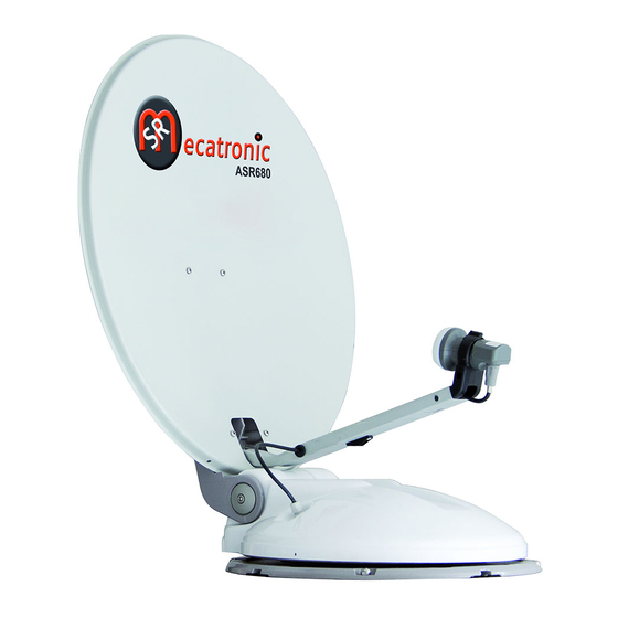
  • Seite 28: Beschreibung

    1.2.3 Die Antenne wurde entwickelt und geprüft, um einer Windgeschwindigkeit von bis zu 120 km/h standzuhalten. Dennoch empfehlen wir, die Antenne bei starkem Windaufkommen zu schließen, da ihre große Fläche das Dach Ihres Wohnmobils starken Belastungen aussetzen würde. 1.2.4 Zur Vermeidung von Beschädigungen und eines unnötigen Batterieverbrauchs muss die Antenne bei Schnee und Eis vor der Betätigung der Öffnungssteuerung gesäu- bert werden.
  • Seite 29: Lieferumfang

    1.4 Lieferumfang Externe Antriebseinheit Offset- Parabol-Antenne mit 60–80 cm Durchmesser Universal-LNB Montageplatte Bedienpanel für Benutzer in Display-Ausführung (nur für die Modelle plus) Wasserdichtes Gehäuse für den Kabeldurchgang nach innen Verkabelung Montage- und Bedienungsanleitung Steuergehäuse für die externe Einheit Rj45 Anschlusskabel an das Bedienpaneel – Steuergehäuse Versorgungsstecker für das Steuergehäuse Bedienpanel für Benutzer in LED-Ausführung (für die Basisausführung)
  • Seite 30: Technische Daten

    1.5 Technische daten • Parabol-Antenne offset • Vollautomatisches Suchsystem mit NID-Erfassung gemäß der Spezifikationen DVB-SI EN 300 468 • In der 1P-Ausführung einstellbare Satelliten In dieser Ausführung ist nur der werkseinge- stellte Satellit verfügbar. (z.B. Hot bird 13E in Italien, Astra 19 in Frankreich und Deutsch- land, usw.) •...
  • Seite 31: Montageanleitung Der Externen Einheit

    2.1 Montageanleitung der externen Einheit ACHTUNG! Vor der Montage die Sicherheitsvorschriften bezüglich der Installation sorgfältig durchlesen. Eventuelle Fehler bei der Einhaltung der Anleitungen kön- nen Personen- oder Sachschäden auch schwerwiegender Natur hervorrufen. 2.1.1 Auf dem Fahrzeugdach eine ausreichend große freie Fläche (möglichst auf der Dachseite) für die Antennenpositionierung ausmachen (siehe Abbil- dung 2) 2.1.2 Die Dachfläche des für die Installation der externen Ein-...
  • Seite 32: Montageanleitung Für Das Gehäuse Für Den Kabeldurchgang

    2.2 Montageanleitung für das Gehäuse für den Kabeldurchgang 2.2.1 Für eine schnelle und einfache Antenneninstallation auf dem Dach des Wohnmobils den genauen Punkt ausmachen, an dem das Versorgungs- und Steuergehäuse installiert werden soll (siehe 2.3.1). 2.2.2 Mit einem Hohlfräser ein Durchgangsloch von 20 mm Durchmesser fräsen, durch das die Kabel in das Fahrzeuginnere geführt werden.
  • Seite 33: Montageanleitung Für Das Steuergehäuse

    2.3 Montageanleitung für das Steuergehäuse Das Steuergehäuse mithilfe von 2 Schrauben auf der rechten oder linken Seite des FS-Raums an der Wand senkrecht befestigen 2.3.1 Im Wohnmobil einen leicht für den Benutzer zugänglichen Bereich ausmachen, der möglichst innerhalb des Standorts des Fernsehers oder in einem Hängeschrank liegen sollte.
  • Seite 34: Elektrische Anschlüsse

    2.4.4 Mithilfe der 4 im Lieferumfang enthaltenen Schrauben die interne Steuereinheit befestigen (siehe Zeichnung. 6 ). 2.5 Elektrische Anschlüsse 2.5.1 Das von der externen Einheit zugeführte graue Kabel an die entsprechenden An- schlüsse auf dem mit externer Einheit bezeichneten Steuergehäuse anschließen (siehe Zeichnung.
  • Seite 35 Dieser Anschluss verhindert die Funktion der Parabolantenne bei gestartetem Fahrzeug oder bei in Richtung Zündung gedrehtem Zündschlüssel. KABELPLAN DER AUSFüHRUNG MIT EINEM AUSGANG HINWEIS: DER DECODER UND DAS ZUGEHÖRIGE KABEL SIND NICHT INBEGRIFFEN ROTES KABEL SCHWARZES KABEL DECODER ZUM ZüNDSCHLüSSEL DES FAHRZEUGS (STROM + 12 V) KABELPLAN DER AUSFüHRUNG MIT ZWEI AUSGäNGEN HINWEIS: DER DECODER UND DAS ZUGEHÖRIGE KABEL SIND NICHT INBEGRIFFEN...
  • Seite 36: Allgemeine Sicherheitsvorschriften

    ALLGEMEINE SICHERHEITSVORSCHRIFTEN ACHTUNG ! lle Anleitungen lesen. Eventuelle Fehler bei der Beachtung folgender Anleitung können folgende Aus- wirkungen haben: Personen- oder Sachschäden, auch schwerwiegender Natur. DIESE ANLEITUNGEN SORGFÄLTIG AUFBEWAHREN 3.1 Arbeitsbereich Vor der Bewilligung der Öffnungssteuerung der Parabolantenne sicherstellen, dass sich keine Hindernisse im Arbeitsbereich der Antenne befinden (Zweige, her- vorstehende Balkons, usw.): GEFAHR DER BESCHäDIGUNG DER PARABOLANTENNE UND DES WOHNMOBILS .
  • Seite 37: Sicherheit Während Der Montagetätigkeiten

    3.4 Sicherheit während der Montagetätigkeiten Für Montagetätigkeiten, die eine Sturzgefahr bergen, müssen angemessene Maßnahmen getroffen werden. Hierzu zählt beispielsweise die Verwendung ei- ner Arbeitsbrücke während auf dem Dach des Wohnmobils auszuführender Tätig- keiten. Außerdem muss sichergestellt werden, dass die Tragkraft des Fahrzeugdachs zur Ausführung der Montagetätigkeiten geeignet ist.
  • Seite 38: Beschreibung Des Bedienpanels Für 1P-Ausführung

    4.2 Beschreibung des Bedienpanels für 1P-Ausführung Einschaltung Zum Einschalten der Antenne die Schaltfläche on/off (3) auf dem Bedienpanel drücken. Beim Drücken der Schaltfläche schalten sich die grünen und roten LED-Anzeigen zur Überprüfung der ordnungsgemäßen LED-Betriebsfähigkeit gleichzeitig ein. Nach einigen Sekunden schaltet sich die rote LED aus und die grüne LED beginnt zu blinken, bis die Antenne den Satelliten empfängt.
  • Seite 39: Beschreibung Des Led-Bedienpanels

    4.2.1 Beschreibung des LED-Bedienpanels LED ALARM LED ALARM FEHLER ALARM LED MAX LED ALARM KABEL RF (5) BEANSPR. (5) FEHLER DREH.(5) BATTERIE EIN(5) LED STROMVERSORG.(2) LED ALARM WOHNMOBIL EIN (5) TASTE PARKEN ANTENNE (6) LED ANZEIGE DES TASTE AUSGEWäHLTEN SATELLITENAUSWAHL (4) TASTE EIN/AUS(3) SATELLITEN (5) 4.2.2 Beschreibung des DISPLAY-Bedienpanels...
  • Seite 40: Einschalten

    4.3 Einschalten Zum Einschalten der Antenne die Schaltfläche on/off (3) auf dem Bedienpanel drücken. Beim Drücken der Schaltfläche schalten sich bei der LED-Ausführung folgende Vorrichtun- gen gleichzeitig ein: Das grüne Versorgungs-LED (2), das den Versorgungsstatus anzeigt Das grüne LED (5) des jeweils gewählten Satelliten, das blinkt, bis die Antenne den Sa- telliten empfängt.
  • Seite 41: Parken Der Antenne

    4.5 Parken der Antenne Zum Parken der Antenne die Schaltfläche (6) drücken. Diese Funktion muss vor dem Ausschalten ausgeführt werden und ermöglicht es, Ihre An- tenne erneut in die Ruhe- und somit Reiseposition zu stellen. Durch das Drücken der entsprechenden Schaltfläche beginnt das grüne LED über den ge- samten zum Schließen der Antenne erforderlichen Zeitraum zu blinken und schaltet sich nach Beendigung dieses Vorgangs ab.
  • Seite 42: Sprachprogrammierung Auf Dem Display

    4.7 Sprachprogrammierung auf dem Display 4.7.1 Insgesamt lassen sich 6 Sprachen auf dem Display einstellen: italienisch, spanisch, französisch, englisch, deutsch, holländisch. 4.7.2. Um Zugang zum Menü der Sprachprogrammierung zu erhalten sind folgende Schritte erforderlich: die Antenne über die Schaltfläche ON (3) einschalten auf den Start warten und die Anten- ne durch das Drücken der Schaltfläche Parking (6) schließen.
  • Seite 43: Entsorgung

    ENTSORGUNG Gemäß Art. 13 der Gesetzesverordnung Nr. 151 vom 25. Juli 2005 „Ausführung der Richtlinien 2002/95/EG, 2002/96/EG, 2003/108/EG, bezüglich einer reduzierten Verwendung gefährlicher Stoffe in elektrischen und elektronischen Geräten sowie der Entsorgung des Mülls“. Das Symbol der mit einem Kreuz versehenen Mülltonne weist darauf hin, dass das Produkt am Ende seiner Nutzungszeit vom übrigen Müll getrennt und nicht zusam- men mit dem Hausmüll zu entsorgen ist.
  • Seite 44: Garantie

    6.2 Garantie 6.2.1 Das Gerät wird ab dem Kaufdatum bezüglich der mechanischen Komponen- ten für 3 Jahre und bezüglich der elektronischen Teile für 2 Jahre garantiert. Der Hersteller garantiert, dass das Gerät äußerst sorgfältig produziert und geprüft wurde und somit vor der Lieferung fehlerfrei ist. 6.2.2 Den Kassenbeleg oder die Rechnung aufbewahren, da diese im Fall von Garantieleis- tungen als Kaufbeleg vorgelegt werden müssen (sofern diese nicht verfallen ist).
  • Seite 45: Konformitätserklärung Des Herstellers

    6.3 KONFORMITÄTSERKLÄRUNG DES HERSTELLERS KONFORMITÄTSERKLÄRUNG “EG Wir, SR Mecatronic, mit Sitz in Aldo Moro 1-3 -40046 Porretta Terme (BO) Italy erklären hiermit eigenverantwortlich, dass das Produkt: AUTOMATISCHE SATELLITENANTENNE ASR folgenden Normen entspricht: Elektromagnetische Kompatibilität : 55022, EN 55024 Maschinensicherheit : 12100-1, EN12100-2, EN294, EN349...
  • Seite 46: Problemlösung

    6.4 Problemlösung PROBLEME URSACHEN ABHILFEN - Die Stromversorgung der Antenne - Das Bedienpanel einschalten fehlt Die Parabolantenne öffnet - Das Hindernis entfernen - Ein Hinderniss über der Antenne sich nicht - Das Wohnmobil ausschalten - Das Wohnmobil fährt - Die Anschlüsse überprüfen - Ein Anschluss hat sich gelöst - Mit dem Wohnmobil die Zonen verlassen, die einen Satelliten-...
  • Seite 47: Fehlerverwaltung Steuereinheit 1 P

    6.4.1 FEHLERVERWALTUNG STEUEREINHEIT 1 P Zum Unterschied von den LED- und DISPLAY-Ausführungen verwaltet diese Steuereinheit die Alarme durch nacheinander erzeugte Licht- und Tonimpulse. Beim Auftreten eines Betriebsfehlers leuchtet die rote LED dauerhaft auf. Zur Feststellung des aufgetretenen Fehlers die Schaltfläche ON/OFF drücken. Eine Reihe Blink- und Tonsignale zeigen die Fehlerarten an, die in der folgenden Tabelle beschrieben sind.
  • Seite 48: Kundendienstzentren

    Pesaro : Car Park Service – C. da Fonte d‘Olmo 7 Montesilvano Tel. 0854-683426 Emilia Romagna: Bologna: SR Mecatronic -Via Aldo Moro 1-3 / 40046 Porretta Terme Tel. 0534 -21477 Bologna: P.I. Service - Via Mascherone 1/3 Castenaso Tel. 051-6050175 Bologna : Camper&Co - Via del Selciatore 19 Bologna...
  • Seite 49: Garantiezertifikat

    GARANTIEZERTIFIKAT : Ausgefüllt an folgende Adresse schicken: SR Mecatronic srl in Aldo Moro 1-3 - 40046 Porretta Terme BO VORNAME NACHNAME STRASSE STADT PROVINZ TELEFON E-MAIL Stempel des Händlers Kaufdatum ........
  • Seite 50 INDICE 1 INTRODUZIONE 1.1 Simbologie utilizzate ..................Pagina 3 1.2 Utilizzo corretto....................Pagina 3 1.3 Descrizione ......................Pagina 4 1.4 Particolari a corredo ..................Pagina 5 1.5 Specifiche tecniche ..................Pagina 6 2 INSTALLAZIONE 2.1 Istruzioni di montaggio dell’ unità esterna ..........Pagina 7 2.2 Istruzioni di montaggio della scatola per passaggio cavi ....Pagina 8 2.3 Istruzioni di montaggio del box di comando .........Pagina 9 2.4 Istruzioni di montaggio dell’...
  • Seite 51: Introduzione

    INTRODUZIONE Congratulazioni per aver acquistato la nostra antenna del tipo ASR a pun- tamento automatico, tecnologicamente e qualitativamente al top nel campo della ricezione televisiva satellitare. Prima dell’ installazione e della messa in funzione dovete studiare bene le funzioni dell’ap- parecchio e vi dovete Informare sull’...
  • Seite 52: Descrizione

    1.2.3 L’ antenna è stata progettata e collaudata per sopportare venti fino a 120 km /h tuttavia In presenza di vento forte consigliamo di tenere chiusa l’ antenna in quanto la sua ampia superficie velica potrebbe generare delle forti sollecitazioni al debole tetto del vostro camper.
  • Seite 53: Particolari A Corredo

    1.4 Particolari a corredo Unità esterna motorizzata Parabola di tipo offset di diametro 65-80 cm LNB universale Piastra di montaggio Pannello di comando per utente versione display ( solo per modelli plus) Scatola a tenuta stagna per passaggio cavi all’ interno Cablaggio Manuale per il montaggio e per l’...
  • Seite 54: Specifiche Tecniche

    Prima di procedere all’installazione aprite l’ imballo in cartone e controllate l’ integrità della parabola e la presenza di tutti gli accessori a corredo indicati sul libretto istru- zioni. (SR Mecatronic non accetta contestazioni per danni causati da trasporto o mancanza di materiale dopo che avete montato l’ antenna).
  • Seite 55: Istruzioni Di Montaggio Dell' Unità Esterna

    2.1 istruzioni di montaggio dell’ unità esterna ATTENZIONE ! Prima di procedere al montaggio leggere attentamente le norme di sicurezza relative all’ installazione eventuali errori nell’ osservanza delle istru- zioni possono provocare danni a persone o cose anche gravi 2.1.1 Individuare sul tetto dell’ automezzo una porzione libera sufficientemen- te ampia (possibilmente ai lati del tetto ) per permettere il posizionamento dell’...
  • Seite 56: Istruzioni Di Montaggio Della Scatola Per Passaggio Cavi

    2.2 istruzioni di montaggio della scatola per passaggio cavi 2.2.1 Per una più veloce e facile installazione dell’ antenna individuare sul tetto del camper il punto esatto sotto il quale verrà installato il box di alimentazione e comando (vedi 2.3.1). 2.2.2 Con una fresa a tazza di diametro 20 praticare un foro passante per permettere il passaggio dei cavi all’...
  • Seite 57: Istruzioni Di Montaggio Del Box Di Comando

    2.3 Istruzioni di montaggio del box di comando Consigliamo di Fissare il Box verticalmente a parete con 2 viti sul lato dx o sx del vano TV 2.3.1 Individuare una zona all’ interno del camper facilmente accessibile all’utente, possibilmente all’interno del vano tv o all’ interno di un pensile. 2.3.2 Posizionare e fissare il box a parete all’...
  • Seite 58: Collegamenti Elettrici

    2.4.4 Mediante le 4 viti a corredo fissare l’unità interna di comando sul camper ( vedi disegno. 6 ). 2.5 collegamenti elettrici 2.5.1 Collegare il cavo grigio proveniente dall’ unità esterna ai corrispettivi connettori situati sul box denominati external unit ( vedi disegno. 7) 2.5.2 Collegare il cavo coassiale nero proveniente dall’...
  • Seite 59 2.5.5 Collegare il cavo verde del connettore di alimentazione al consenso della con- solle di avviamento dell’ automezzo per permettere l’ abbassamento in automatico della parabola quando si prova ad accendere il mezzo con la parabola aperta. In molti casi il consenso si trova sul pin 15 della morsettiera generale e in ogni caso corri- sponde ad una tensione positiva di +12 VDC generata quando si gira la chiave di accen- sione del mezzo.
  • Seite 60: Norme Generali Di Sicurezza

    NORME GENERALI DI SICUREZZA ATTENZIONE ! Leggere tutte le istruzioni. Eventuali errori nell’ osservanza delle istruzioni riportate di seguito possono pro- vocare danni a persone o cose anche gravi . CONSERVARE BENE QUESTE ISTRUZIONI Area di lavoro Prima di dare il consenso al comando di apertura della parabola assicurarsi che l’ area di lavoro della Parabola sia sgombera da ostacoli ( rami di alberi, balconi spor- genti, ecc.
  • Seite 61: Sicurezza Durante Le Operazioni Di Montaggio

    Sicurezza durante le operazioni di montaggio Per le operazioni di montaggio a rischio di caduta è necessario adottare misure di sicurezza Idonee come ad esempio un ponte di lavoro quando operate sul tetto del camper. Accertatevi inoltre che il tetto del veicolo abbia una portata sufficiente per eseguire le operazioni di Montaggio.
  • Seite 62: Descrizione Del Pannello Comandi Per Versione 1P

    4.2. Descrizione del Pannello comandi per versione 1P Accensione Per accendere la vostra antenna premete il tasto di on / off (3) del pannello di comando. Alla pressione del tasto si accenderanno simultaneamente i LED verde e rosso per verifi- care la corretta funzionalità...
  • Seite 63 4.2.1 Descrizione del Pannello comandi per versione LED LED ALLARME LED ALLARME LED ALLARME LED ALLARME ERRORE CAVO RF (5) SFORZO MAX (5) ERRORE ROT (5) BATTERIA INS. (5) DI ALIMENTAZIONE (2) LED ALLARME CAMPER ACCESO (5) TASTO DI PARCHEGGIO ANTENNA (6) TASTO DI SELEZIONE LED DI INDICAZIONE...
  • Seite 64: Accensione

    Accensione Per accendere la vostra antenna premete il tasto di on / off (3) del pannello di comando. Alla pressione del tasto si accenderanno simultaneamente nella versione a led: -il led verde di alimentazione (2) per indicare lo stato di alimentazione -il led verde (5) relativo al satellite selezionato in modalità...
  • Seite 65: Parcheggio Dell' Antenna

    4.5 Parcheggio dell’ antenna Per parcheggiare l’ antenna premete il tasto (6). Questa funzione và eseguita sempre prima di effettuare lo spegnimento e permette di riportare in posizione di riposo e quindi di viaggio la vostra antenna. Premendo il tasto relativo a questa funzione il led verde comincerà a lampeggia- re per tutto il tempo necessario alla chiusura dell’...
  • Seite 66: Note Particolari

    4.7 Programmazione delle lingue sul display 4.7.1 Le lingue programmabili nel display sono 6 e più precisamente : Italiano, Spagnolo, Francese, Inglese, Tedesco, Olandese. 4.7.2. Per accedere al menù di programmazione lingue è necessario : - Accendere l’ antenna con tasto ON (3) - Attendere la partenza e riportare in chiusura l’...
  • Seite 67: Smaltimento

    SMALTIMENTO Ai sensi dell’ art. 13 del decreto legislativo n° 151 del 25-luglio 2005 “ attuazione delle direttive 2002/95/CE , 2002/96/CE , 2003/108/CE , relative alla riduzione dell’ uso di sostanze pericolose nelle apparecchiature elettriche ed elettroniche, nonché allo smaltimento dei rifiuti “. Il simbolo del cassonetto barrato indica che il prodotto alla fine della propria vita utile deve essere smaltito separatamente dagli altri rifiuti e non può...
  • Seite 68: Garanzia

    6.2.1 L’ apparecchio è garantito 3 anni dalla data di acquisto per tutte le parti meccaniche e 2 anni per le Parti elettroniche. SR Mecatronic garantisce che l’ apparecchio e stato prodotto e collaudato con estrema cura e pertanto privo di difetti prima della consegna .
  • Seite 69: Dichiarazione Di Conformità Del Produttore

    Dichiarazione di conformità del produttore DICHIARAZIONE DI CONFORMITA’ CE SR Mecatronic srl Via Aldo Moro 1-3 -40046 Porretta Terme (BO) Italy Dichiariamo sotto la nostra responsabilità che il prodotto: ANTENNA SATELLITARE AUTOMATICA Type ASR E’ conforme alle seguenti norme : Compatibilità...
  • Seite 70: Risoluzione Problemi

    6.4 Risoluzione problemi PROBLEMI CAUSE RIMEDI La parabola non si apre -Manca l’ alimentazione all’ antenna -accendere il pannello comandi -Presenza di un’ ostacolo sopra l’ - rimuovere l’ ostacolo antenna - spegnere il camper -il camper è in moto - verificare le connessioni -si e’...
  • Seite 71: Tipo Di Allarme

    6.4.1 GESTIONE ERRORI CENTRALINA 1 P A differenza delle versioni LED e DISPLAY questo tipo di centralina gestisce gli allarmi me- diante impulsi luminosi e sonori in sequenza. Quando compare un’ errore di funzionamento si accende in modo fisso il led rosso. Per capire di quale tipo di errore si tratta è...
  • Seite 72: Centri Assistenza

    Pesaro : Car Park Service – C.da Fonte d’Olmo 7 Montesilvano Tel . 0854-683426 Emilia Romagna: Bologna : SR Mecatronic srl -Via Aldo Moro 1-3 / 40046 Porretta Terme Tel . 0534 -21477 Bologna : P.I. Service - Via Mascherone 1/3 Castenaso Tel .
  • Seite 73: Certificato Di Garanzia

    CERTIFICATO DI GARANZIA : Compilare e spedire a SR Mecatronic srl Via Aldo Moro 1 - 3 - 40046 Porretta Terme BO NOME COGNOME CITTA’ CAP. PROVINCIA TELEFONO E–MAIL Timbro del rivenditore Data di acquisto ........
  • Seite 76 SR Mecatronic srl Via Aldo Moro 1-3 40046 Porretta Terme (BO) Italy info@srmecatronic.com www. srmecatronic.com code: 110002096 SR Mecatronic: reserves the right to make changes without notice - Rev 02 of 02-02-13 behält sich das Recht vor, Änderungen ohne Vorankündigung vornehmen zu können. - Überarb. 02 vom 02.02.13...

Inhaltsverzeichnis