Herunterladen Inhalt Inhalt Diese Seite drucken
Mediclinics M14A-UL Benutzerhandbuch
Vorschau ausblenden Andere Handbücher für M14A-UL:

Werbung

Verfügbare Sprachen

Verfügbare Sprachen

www.mediclinics.com
SECADORA DE MANOS / HAND DRYERS / SÉCHE-MAINS /
HÄNDETROCKNER
M14A-UL / M14ACS-UL
MANUAL DE INSTALACIÓN Y UTILIZACIÓN
INSTALLATION AND OPERATING MANUAL
MANUEL D'INSTALLATION ET D'UTILISATION
MONTAGE-UND BENUTZERHANDBUCH

Werbung

Inhaltsverzeichnis
loading

Inhaltszusammenfassung für Mediclinics M14A-UL

  • Seite 1 SECADORA DE MANOS / HAND DRYERS / SÉCHE-MAINS / HÄNDETROCKNER M14A-UL / M14ACS-UL MANUAL DE INSTALACIÓN Y UTILIZACIÓN INSTALLATION AND OPERATING MANUAL MANUEL D’INSTALLATION ET D’UTILISATION MONTAGE-UND BENUTZERHANDBUCH...
  • Seite 2 óptimo entre la potencia de secado y el nivel de ruido acústico.  Acabados disponibles: Blanco (M14A-UL) Satinado (M14ACS-UL)  Dimensiones: 665 mm (26 1/8”) (H) x 320 mm (12 5/8”) (W) x 228 mm (9”) (D).
  • Seite 3: Instalación

    INSTALACIÓN Y MANTENIMIENTO PARA EL PERSONAL TÉCNICO LEER Y GUARDAR ESTE MANUAL Introducción. Las secadoras de manos que integran la familia ‘Dualflow Plus’ ofrecen las siguientes características técnicas:  Funcionamiento automático. El ciclo de secado empieza cuando el usuario introduce las manos.
  • Seite 4 Por tanto para fijar la secadora de manos a la pared hay que seguir los siguientes pasos:  Realizar cinco agujeros de 8 mm (0.31”) de diámetro en la pared, utilizando la plantilla suministrada (1).  Limpiar todo el polvo de los agujeros realizados e insertar los tacos. ...
  • Seite 5 La altura de instalación de la secadora de manos a la pared debe ser la que se indica en la figura nº 3. Figura nº 3 ATENCIÓN: CUANDO SE DESMONTA LA CARCASA PARTES ACTIVAS DEL APARATO QUEDAN ACCESIBLES.
  • Seite 6: Mantenimiento

    Mantenimiento. SÓLO UN TÉCNICO CALIFICADO PUEDE REALIZAR LA INSTALACIÓN, LOS AJUSTES NECESARIOS Y EL MANTENIMIENTO DE ESTE SECADORA DE MANOS. Ajuste de la velocidad del motor. Para ajustar la velocidad del motor girar la rueda del potenciómetro del sensor tal y como se indica en la figura nº...
  • Seite 7: Filtro Del Aire

    Filtro del aire. El filtro del aire debe se cambia tal y como se muestra en la figura nº 6. . Figura nº 6 Pastilla anti malos olores. La figura nº 7 muestra como instalar la pastilla anti malos olores.
  • Seite 8: Diagrama De Conexión

    DIAGRAMA DE CONEXIÓN DIAGRAMA ELÉCTRICO S = Sensor F = Fusible térmico H = Resistencia calefactora M = Motor K = Limitador térmico auto-reseteable Figura nº 9 Cables del circuito impreso del emisor IR Cables del circuito impreso del receptor IR Cables de Cables del circuito impreso de los LED indicadores alimentación...
  • Seite 9 DESPIECE BÁSICO COMPONENTE NUMERO CODIGO Conjunto motor RC9111003UL Circuito electrónico RC9121012UL Set filtro de aire RCFILTROHEPA1 Filtro HEPA RCFILTROHEPA2 Resistencia calefactora RC9141002UL Pastilla desodorante 9481002...
  • Seite 10: Operation

    The speed of the air generated by the hand dryer can be adjusted, to achieve an optimum balance between the drying power and noise level.  Available finishes: White (M14A-UL) Satin (M14ACS-UL)  Dimensions: 665 mm (26 1/8”) (H) x 320 mm (12 5/8”) (W) x 228 mm (9”) (D).
  • Seite 11: Installation

    INSTALLATION AND MAINTENANCE BOOK (TECHNICAL STAFF) READ AND SAVE THESE INSTRUCTIONS Introduction. ‘Dualflow Plus’ family of hand dryers offers the technical features as follows.  Automatic operation. Drying cycle starts when putting hands in. Two couple of IR sensors detect hands introduction.
  • Seite 12  Pass the electrical cables from mains through the 22 mm (0.87”) diameter hole located in the rear plastic base plate. (5).  Connect the electrical wires to the hand dryer terminal block. Two phases (N,L) and earth wires must be screwed in the right ways of the terminal block, as indicated by the engraved letters (6).
  • Seite 13 Installation height must be the showed in figure nº 3. Figure 3 ATTENTION: WHEN THE CASING IS DISMANTELED ACTIVE PARTS OF THE DEVICE BECOME ACCESSIBLE. -13-...
  • Seite 14: Maintenance

    Maintenance. ONLY A QUALIFIED TECHNICIAN CAN INSTALL, ADJUST AND MAINTAIN THIS HAND DRYER. Adjust the speed of the motor. To adjust the speed of the motor turn the sensor potentiometer wheel as the picture 4 shows. Figure 4 Disconnecting the heating element. The heating element may be disconnected by switching the switch to (OFF) as shown in Fig.
  • Seite 15: Air Filter

    Air filter Air filter must be changed as the pictures of figure nº 6 shows. Figure 6 No smell load charge Figure nº 7 shows how to install the no smell charge. Figure 7 Water tank. Water from hands drops directly to a removable water tank. When water from the removable water tank reaches the ‘full level’...
  • Seite 16: Connection Diagram

    CONNECTION DIAGRAM Figure nº 9 Figure 10 - The installer must make sure that the electric system is grounded in accordance with the law in force. DANGER. - Make sure that the electric system has a high-sensitivity Electric shock risk breaker I n ≤...
  • Seite 17 BASIC EXPLODED VIEW COMPONENTE NUMERO CODIGO Motor set RC9111003UL Electronic control RC9121012UL Air filter set RCFILTROHEPA1 HEPA filter RCFILTROHEPA2 Heating element RC9141002UL Air-freshener 9481002 -17-...
  • Seite 18 La vitesse de l’air fourni par le sèche-mains est réglable, de façon à obtenir un équilibre optimal entre la puissance de séchage et le niveau de bruit.  Finitions disponibles : Blanc (M14A-UL) Satin (M14ACS-UL)  Dimensions : 665 mm (26 1/8”) (H) x 320 mm (12 5/8”) (W) x 228 mm (9”) (D).
  • Seite 19 MANUEL D’INSTALLATION ET D’ENTRETIEN (ÉQUIPE TECHNIQUE) LIRE ET CONSERVER CE MANUEL D'UTILISATION Introduction La gamme de sèche-mains ‘Dualflow Plus’ propose les caractéristiques techniques suivantes :  Fonctionnement automatique. Le cycle de séchage commence lorsque les mains sont placées à l’intérieur du sèche-mains. Deux paires de capteurs à infrarouges détectent l’introduction des mains.
  • Seite 20  Retirer les couvercles en plastique qui protègent la plaquette de connexion (arrivée d’alimentation) (3).  Accrocher le sèche-mains au support métallique qui a été fixé au mur (4).  Passer les câbles électriques qui proviennent du réseau à travers les orifices de 22 mm de diamètre situés sur le socle arrière en plastique.
  • Seite 21 La hauteur d’installation doit être celle indiquée sur la figure 3. Figure 3 ATTENTION : LORSQUE LE BOÎTIER EST DÉMONTÉ, CERTAINES PIÈCES ACTIVES DE L’APPAREIL DEVIENNENT ACCESSIBLES. -21-...
  • Seite 22: Entretien

    Entretien. LE MONTAGE, LE RÉGLAGE ET L’ENTRETIEN DE CE SÈCHE-MAINS DOIVENT UNIQUEMENT ÊTRE EFFECTUÉS PAR DES TECHNICIENS QUALIFIÉS. Réglage de la vitesse du moteur. Pour régler la vitesse du moteur, tourner le curseur du potentiomètre du capteur, comme indiqué sur la figure 4. Figure 4 Déconnexion de la résistance chauffante Pour déconnecter la résistance, il faut changer la position de l'interrupteur comme sur la Fig.
  • Seite 23: Filtre À Air

    Filtre à air Le filtre à air doit être remplacé en suivant les indications de la figure 6. Figure 6 Cartouche anti-odeur La figure 7 indique comment installer la cartouche anti-odeur. Figure 7 Réservoir d’eau L’eau provenant du sèche-mains est collectée dans un réservoir amovible. Lorsque l’eau du réservoir atteint la limite, une alarme sonore retentit et la LED bleue s’allume (voir figure 5).
  • Seite 24: Schéma De Câblage

    SCHÉMA DE CÂBLAGE SCHÉMA ÉLECTRIQUE S - Capteur M – Moteur F – Fusible thérmique H- Résistance K- Thermal cut-out Figure 9 Câbles circuit imprimé, émetteur Câbles circuit imprimé, récepteur Câbles circuit imprimé, LED éclairage informations Câbles d’alimentation Capteur de niveau d’eau Interrupteur du résistance Câbles du moteur Vibreur...
  • Seite 25 VUE ÉCLATÉE DE BASE COMPONENTE NUMERO CODIGO Groupe moteur RC9111003UL Commande électronique RC9121012UL Ensemble de filtre à air RCFILTROHEPA1 HEPA filtre RCFILTROHEPA2 Résistance RC9141002UL Cartouche anti-odeur 9481002 -25-...
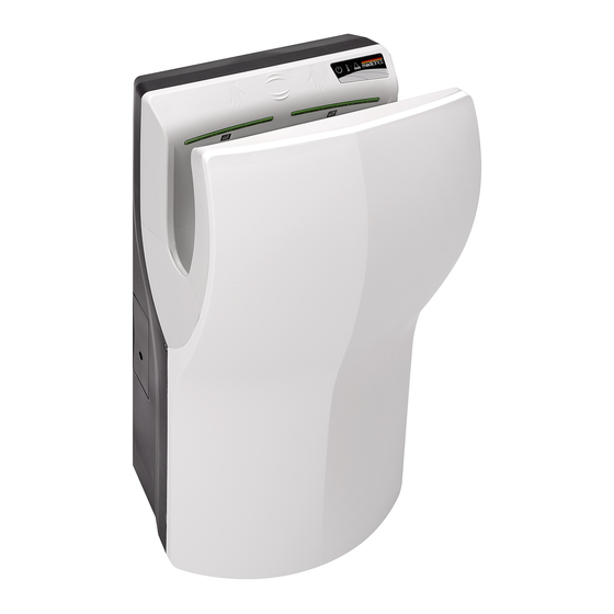
  • Seite 26 Infrarotsensoren (Sender und Empfänger)  Optionale Luftstromregulierung  Mögliches Oberflächenfinish: Weiß (M14A-UL) Seidenmatt (M14ACS-UL)  Abmessungen: 665 mm (26 1/8”) (H) x 320 mm (12 5/8”) (W) x 228 mm (9”) (D).  Gewicht: 8.3 Kg (18.3 lb)  Montage: Aufputz FUNKTION Die Hände ins Innere des Trockners stecken.
  • Seite 27: Montage- Und Wartungsanleitung (Fachpersonal)

    MONTAGE- UND WARTUNGSANLEITUNG (FACHPERSONAL) Einleitung Die ‘Dualflow Plus’ Handtrocknerserie bietet folgende technischen Leistungen:  Automatischer Betrieb. Sobald die Hände hineingesteckt werden, empfangen zwei Paar Infrarotsensoren die Bewegung und der Trockner schaltet sich automatisch ein.  Der Händetrockner ist ein Gerät mit einem Erdanschluss. Es ist notwendig und unverzichtbar, diesen mit einer Erdleitung zu verbinden.
  • Seite 28  Bohren Sie mithilfe der mitgelieferten Schablone fünf Löcher mit einem Durchmesser von 8 mm in die Wand (1).  Reinigen Sie die Stellen von Staub und fügen Sie die Dübel ein.  Schrauben Sie die obere Platte an der Wand fest (2). ...
  • Seite 29 Die Installationshöhe muss der Abbildung 3 entsprechen. Abbildung 3 ACHTUNG: BEI ABMONTIERTEM GEHÄUSE LIEGEN DIE SPANNUNGSFÜHRENDEN TEILE DES GERÄTES FREI. -29-...
  • Seite 30: Wartung

    Wartung MONTAGE, EINSTELLUNGEN UND WARTUNG DIESES HÄNDETROCKNERS DÜRFEN NUR VON QUALIFIZIERTEM FACHPERSONAL DURCHGEFÜHRT WERDEN. Einstellung der Motordrehzahl Drehen Sie das Sensor-Potenziometerrad wie in Abbildung 4, um die Motordrehzahl zu regulieren. Abbildung 4 Den Heizwiderstand abschalten. Sie können den Heizwiderstand am entsprechenden Schalter (siehe Abbildung 4) abschalten (OFF).
  • Seite 31: Austausch Des Aromatisierers

    Luftfilter Der Luftfilter ist auszuwechseln, wie in Abbildung 6 dargestellt. Abbildung 6 Austausch des Aromatisierers In Abbildung 7 sehen Sie, wie der Antigeruchseinsatz zu installieren ist. Abbildung 7 Wasserbehälter Das Wasser aus dem Trockner wird in einem herausnehmbaren Behälter gesammelt. Wenn die maximale Kapazität des Wasserbehälters erreicht ist, ertönt ein akustischer Alarm und die...
  • Seite 32: Anschlussdiagramm

    ANSCHLUSSDIAGRAMM S – Sensor M – Motor F – Sicherung H – Heizwiderstand K – Klixon Abbildung 9 PCB-Kabel des Infrarotsenders Versorgungskabel PCB-Kabel des Infrarotempfängers PCB-Kabel der LED-Anzeigen Wasserstandssensor Heizwiderstandswitch Motorkabel Summer Summer Heizwiderstandkabel Information Motor-Einstellpotentiometer Abbildung 10 - Der Elektroinstallateur muss sich vergewissern, dass die Elektronik über einen den gültigen gesetzlichen Bestimmungen entsprechenden Erdanschluss verfügt.
  • Seite 33: Grundlegende Explosionszeichnung

    GRUNDLEGENDE EXPLOSIONSZEICHNUNG COMPONENTE NUMERO CODIGO Motorset RC9111003UL Elektronische Regelung RC9121012UL Luftfilterset RCFILTROHEPA1 HEPA filter RCFILTROHEPA2 Heizwiderstand RC9141002UL Antigeruchseinsatz 9481002 -33-...
  • Seite 34 MODELO MODEL MODÈLE MODELL M14A M14ACS GENERAL: GENERAL: GÉNÉRAL : ALLGEMEIN: Blanco / White Satinado / Satin / Acabado: Finish: Finition : Finish: / Blanche / Satiné / Satiniert Weiβ 100 – 120 VAC, 208 VAC, 220-240 Alimentación: Power supply: Alimentation : Stromversorgung: VAC / 60 Hz...
  • Seite 35 ANEXO INSTRUCCIONES DE MONTAJE.  Antes de montar la secadora de manos en la pared se debe verificar que no hayan cables eléctricos o tuberías de agua justo en la zona de montaje.  Colocar la plantilla de montaje que se suministra con la secadora de manos en la pared y marcar los agujeros de los tornillos de fijación.
  • Seite 36 ANNEX MOUNTING INSTRUCTIONS.  To mount onto wall, be sure there are no hidden electrical circuits or pipes in the mounting location.  Place the mounting template (provided) on the wall to mark location of four mounting screw holes.  Drill 5 holes (Fig.1) Ø8 (5/16”) diameter and 45mm (1 ¾”) depth.
  • Seite 37 ANNEXE INSTRUCTIONS DE MONTAGE  En cas de montage sur un mur, s'assurer qu'aucun circuit électrique et qu'aucun tuyau ne sont dissimulés derrière l'emplacement choisi pour le montage.  Placer le modèle de montage (fourni) sur la paroi pour marquer l'emplacement des quatre trous pour les vis.
  • Seite 38 ANHANG MONTAGEANLEITUNG.  Bevor Sie den händetrockner an der Wand montieren, müssen Sie sich vergewissern, dass keine Stromkabel oder Wasserleitungen im Montagebereich verlaufen.  Legen Sie die mit dem händetrockner mitgelieferte Montageschablone an die Wand an und markieren Sie die Stellen der Löcher für die Befestigungsschrauben. ...
  • Seite 39 -39-...
  • Seite 40 USA – ESTADOS UNIDOS - SPAIN – ESPAÑA - ESPAGNE ETATS UNIS MEDICLINICS, S.A. Saniflow Corporation Industria, 54 12800 N.W. 38 Avenue E-08025 BARCELONA Miami FL 33054-4525 Tel.: +34 93 446 47 00 Tel: 305 424 24 33 Fax: +34 93 348 10 39 Fax: 305 424 24 35 nfo@saniflowcorp.c...

Diese Anleitung auch für:

M14acs-ul

Inhaltsverzeichnis