DigiTrace HTC-915 Installationshandbuch
Verfügbare Sprachen
Verfügbare Sprachen
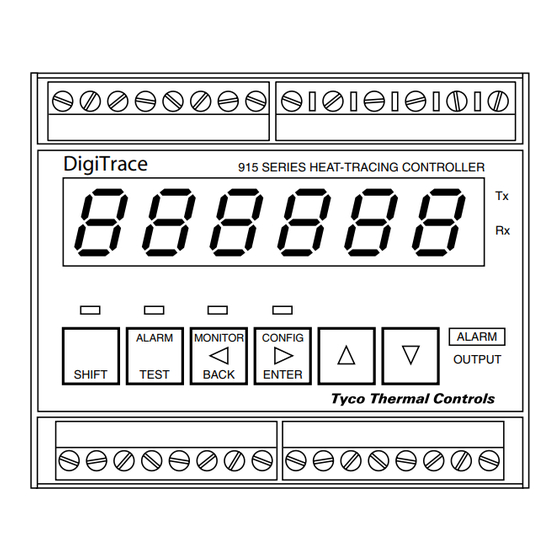
HTC-915
Universal heat tracing control system
CAUTION: installation, configuration and commissioning
should only be performed by properly trained personnel.
Local regulations regarding the installation & safety must
be followed.
FUNCTIONAL OVERVIEW
The DigiTrace HTC-915 is a full featured temperature control system for
heattracing applications.
Power supply
HTC-915
100 to 250V
Controller
±10% at 50/60Hz
(also used
for voltage
measurements)
2 three wire
PT100 inputs
Current
Transformer
Load current
Current
Transformer
Earth leakage current
HTC-915
Current
Limiter
Transformer
Load current
3-wire PT100
input
ThERMAL MANAgEMENT SOLUTIONS
ML-DigiTraceHTC915-IM-INSTALL092-R1
PRODUCT DIMENSIONS
Controller Dimensions
DigiTrace
75
ALARM
MONI TO R
SHIF T
TEST
BACK
Limiter dimensions
45
HEA TER
POWE R
Digital
CURRENT
ALAR M
Tx /R x
75
communication
Configuration
TRIP
RESET
and set-up
Software (RS485)
Control
Relay output
INSTALLATION
(250V/3A)
Ensure all personnel involved in installation, servicing, and programming are
qualified and familiar with electrical equipment, their ratings and proper
Control
practices and codes.
Solid state output
(0 – 12Vdc)
Installation Location
Considerations should include expected atmospheric conditions, accessibility
Alarm output
for maintenance, testing and ambient temperature. The conditions at the place
(relay 250V/3A)
of installation may affect load current ratings.
Configurable to open
or to close on alarm
Operator Safety Considerations
Caution: Some wiring configurations will use more than one power source and
Scrolling display
all must be de-energized prior to performing any maintenance on a control
circuit.
Warning: The HTC-915 control module must be protected by external over
current and disconnect devices.
Mounting Procedures
Alarm output
The HTC-915-CONT and HTC-915-LIM are designed for installation
(relay 250V/3A)
on a standard 35 mm x 7.5 mm (EN50022 compatible) DIN rail.
NC opening on alarm
Pollution Degree 2
Trip
Altitude 0-2000m
Relay output
(250V/3A)
90
105
915 SERIES HEA T -TRACING CONTROLLER
Tx
Rx
CONFI G
ALAR M
OUTPU T
ENTER
105
915 SERIES
LIMITER
MAINTENANCE
Operator Maintenance
The HTC-915 control system is designed to be a maintenance free product.
Replaceable Parts
There are no user-serviceable parts in the HTC-915 series controller or
accessories. The unit is designed to be easily changed out in the field in a matter
of minutes.
Any HTC-915 system component appearing inoperative should be returned to
the nearest Pentair Thermal Management office.
Cleaning
If the HTC-915 components require cleaning, a damp cloth may be used to
wipe the units. This should only be done while the units are disconnected from
their power source. Do not use any harsh chemicals or solvents, as this may
damage the housing or finish.
ELECTRICAL CONNECTION
Connections are made via screw connections suitable to accept cable diameters
between 0.5 and 2.5 mm
(24 to 12 Awg). Either solid or stranded wires may be
2
used.
Do not rely on the controller as a disconnect device!
Installation notes
• If contact with live parts is possible while working on the unit, it must be
completely isolated from the mains supply. Be aware that the unit might have
cables connected to it which are powered from different sources.
• Magnetic or electric fields, eg: from transformers, mobile phones or
electrostatic discharge must be avoided in the vicinity of the instrument.
• Route input, output and supply lines separately.
• Arrange sensor cable extensions as twisted and screened cables. Do not
run them close to power cables. The shield, if any, shall be earthed on the
controller's side only.
• Fluctuations in the supply signals are only permissible within the specified
tolerances.
All Pentair trademarks and logos are owned by Pentair or its global affiliates. Pentair reserves the right to change
specifications without prior notice.
© 2013 Pentair All Rights Reserved.
ThERMAL MANAgEMENT SOLUTIONS
ML-DigiTraceHTC915-IM-INSTALL092-R1
www.thermal.pentair.com
Inhaltsverzeichnis

Inhaltszusammenfassung für DigiTrace HTC-915
- Seite 5 Die Reinigung darf nur vorgenommen werden, wenn die Module von ihrer Installations- und Sicherheitsbestimmungen müssen Abmessungen des Begrenzers Netzversorgung freigeschaltet worden sind. Verwenden Sie keine scharfen eingehalten werden. chemischen Reinigungs- oder Lösungsmittel. Diese könnten das Gehäuse oder deren Oberfläche nachhaltig beschädigen. FUNKTIONSÜBERSIChT Das Steuermodul DigiTrace HTC-915 ist ein Steuersystem für Begleitheizungen ELEKTRISChE ANSChLÜSSE mit uneingeschränktem Funktionsumfang. 915 SERIES Die Anschlüsse erfolgen mit Schraubklemmen, die für Kabeldurchmesser von LIMITER 0,5 bis 2,5 mm (24 bis 12 AWG) ausgelegt sind. Es können Leitungen mit Volldraht HEA TER...
-
Seite 6: Bedienfeld & Betrieb
• wechseln zum nächsten Menüpunkt oder Í Alarmmeldungen sind verfügbar für: Temperatur, Spannung, Stromstärke, Verringerung des zu bearbeitenden Werts. Erdschlussfehlerstrom usw. Beziehen Sie sich für Einzelheiten dazu auf das Betriebshandbuch HTC-915 (DOC-2106). Eine Kopie dieses Handbuchs kann von LED-ANZEIgEN unserer Site www.thermal.pentair.com heruntergeladen werden. Das Bedienfeld weist acht LED-Anzeigen auf: BEDIENFELD & BETRIEB Vier LEDs für die Anzeige der -Betriebsart. (ShIFT-Funktion, ALARM, MONITOR oder CONFIg). -
Seite 7: Programmierung Des Begrenzermoduls
Soll ein Begrenzer aus dem System entfernt werden, so muss er über die Um die konfiguration des Steuermoduls zu ändern: EINEM OPTIONELLEN BEgRENZERMODUL hTC-915-LIM • Zeigen Sie den entsprechenden Parameter (Menüpunkt) auf der Anzeige an. Software de-installiert werden. Dies kann über das Untermenü „Misc. Setup“ des • Betätigen Sie die Taste Ë, um die Bearbeitung zu beginnen. HTC-915-CONT erfolgen. Anders als bei der Installation des Begrenzers muss der BEgRENZER- ANSChLUSSPLAN Benutzer jetzt vor der Betätigung der Taste CONFIG die Taste SHIFT betätigen, um • Wenn die Konsole „gesperrt“ ist, werden Sie aufgefordert, Ihr Passwort ANSChLUSSKLEMMENBELEgUNg das entfernen des Begrenzers zu bestätigen. - Seite 8 ANhANg – KONFIgURATIONSBLATT WEITERES TS ALARM-KONFIgURATIONS-UNTERMENÜ Max. Strom *k/A (30.0 A) 915 hTC Konfiguration – Firmware-Version 1.0x Parameter Fabrikseitig User Leist.-Berechnung 3 Ph. Keine Strom niedrig Aktiviert TS-Fehler-Wirksinn BASIS-BETRIEBSARTENMENÜ Alle anderen Parameter werden, wie in den fortgeschrittenen Betriebsarten- Strom niedrig 1.0 A TS-Regelungsart TS1 Fehler aus U-)àtermenüs dargestellt, festgelegt.)