Herunterladen Inhalt Inhalt Diese Seite drucken
Hameg HM8135 Benutzerhandbuch
Vorschau ausblenden Andere Handbücher für HM8135:
Inhaltsverzeichnis

Werbung

Verfügbare Sprachen

Verfügbare Sprachen

3 G H z R F - S y n t h e s i z e r
HM8135 / HM8135-X
H M 8 1 3 5 , H M 8 1 3 5 - X
3 GHz RF-Synthesizer
Benutzerhandbuch
User Manual
*5800435702*
Optional HO880 IEEE-488
5800435702
(GPIB) Schnittstelle
Wahl der Modulationsart
3 G H z H F - S y n t h e s i z e r
H M 8 1 3 5 | H M 8 1 3 5 - X
Frequenzbereich: 1 H z bis 3 G Hz
R
Hoher dynamischer Ausgangspegel: -135 d Bm bis +13 d Bm
R
Frequenzauflösung: 1 H z
R
Hohe spektrale Reinheit, exzellente SWEEP Funktion
R
Modulationsarten: AM, FM, Puls, Phase, FSK, PSK
R
I nterne Modulation (10Hz bis 200kHz):
R
Sinus, Rechteck, Dreieck, Rampe
E xterner Ref.-Eingang/Ausgang (10MHz) über BNC-Anschluss
R
H M8135:
TCXO (Temperaturstabilität: ±0,5 x 10
R
HM8135-X: OCXO (Temperaturstabilität: ±1,0 x 10
Handbuch / Manual
Deutsch / English
)
-6
)
-8

Werbung

Kapitel

Inhaltsverzeichnis
loading

Inhaltszusammenfassung für Hameg HM8135

  • Seite 1 3 G H z R F - S y n t h e s i z e r HM8135 / HM8135-X H M 8 1 3 5 , H M 8 1 3 5 - X 3 GHz RF-Synthesizer Benutzerhandbuch...
  • Seite 2: Allgemeine Hinweise Zur Ce-Kennzeichnung

    Industriestraße 6 · D-63533 Mainhausen die Einhaltung der vorgegebenen Grenzwerte in erheblicher Weise. Die verwendeten Leitungen sind jedoch je nach An- Die HAMEG Instruments GmbH bescheinigt die Konformität für das Produkt: wendungsbereich unterschiedlich. Im praktischen Messbe- Bezeichnung: HF- Synthesizer 3 GHz trieb sind daher in Bezug auf Störaussendung bzw.
  • Seite 3: Inhaltsverzeichnis

    6.15 Befehle PM (Phasen-Modulation) ....20 Die Bedienung des HM8135 ....7 6.16 Befehle FSK (FSK Modulation) ....21 Inbetriebnahme .
  • Seite 4: Wichtige Hinweise

    (Neigung etwa 10°). Bleiben die vorderen Gerä- tefüße eingeklappt (Abb. 2), lässt sich das Gerät mit weite- Bestimmungsgemäßer Betrieb ren HAMEG-Geräten sicher stapeln. Werden mehrere Ge- Die Geräte sind zum Gebrauch in sauberen, trockenen räte aufeinander gestellt, sitzen die eingeklappten Geräte- Räumen bestimmt.
  • Seite 5: Gewährleistung Und Reparatur

    Wichtige Hinweise det, muss das Gerät ca. 2 Stunden akklimatisiert werden, ❙ Die Außenseite des Gerätes sollte regelmäßig mit einem weichen, bevor es in Betrieb genommen wird. Das Gerät darf aus Si- nicht fasernden Staubtuch gereinigt werden. cherheitsgründen nur an vorschriftsmäßigen Schutzkon- ❙...
  • Seite 6: Bezeichnung Der Bedienelemente

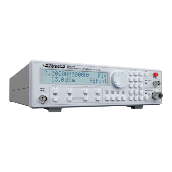
    REF. INPUT 10 MHz: Referenzsignaleingang MENU: Taste zum Aufruf des Konfigurations-Menüs RS-232 Schnittstelle DISPLAY: Alphanumerische Anzeige, bestehend aus zwei Zeilen mit jeweils 20 Zeichen. Hintergrundbe- USB/RS-232 Schnittstelle (HO820) optional: IEEE-488 leuchtete LCD GPIB (HO880) Abb. 2.1: Frontansicht des HM8135 Abb. 2.2: Rückansicht des HM8135...
  • Seite 7: Die Bedienung Des Hm8135

    Signalform (SQR = square wave) und Modulationsfrequenz Nach Betätigung des roten Netzschalters erscheinen (Fmod = 1 kHz) angezeigt. auf dem Display des HM8135 die folgenden Nachrichten: ❙ der Gerätetyp (SYNTHESIZER) und die Versionsbezeich- nung (HM8135) ❙ eine Selbsttestnachricht „RAM checking“ und „DDS loading“...
  • Seite 8: Wahl Der Frequenz

    Die Bedienung des HM8135 Die Werterhöhung oder Wertminderung erfolgt mit dem Die Modulationsart wird nun mit den kontextsensitiven Ta- Drehknopf . Wird eine Leerstelle unterstrichen, gilt diese sten ausgewählt: Stelle als Null und kann mit jedem Wert belegt werden. ❙ AM (Amplituden-Modulation) Eine falsche Eingabe wird mit einer Nachricht und einem ❙...
  • Seite 9 Die Bedienung des HM8135 Durch einmaliges Drücken der kontextsensitiven Taste In diesem Beispiel besteht das externe Modulationssignal unterhalb der Anzeige OFF wird die interne Modulations- aus einem TRINARY-Code, bestehend aus 9 Bits, 1 Bit be- quelle eingeschaltet (INT). Bei nochmaligen Drücken wird steht aus zwei schmalen oder breiten Impulsen, abhängig...
  • Seite 10: Modulationsarten

    Modulationsarten 4 Modulations- Beispiel 5: Für AM Dreieck (Modulationsgrad: 50%) erhält man: arten Amplitudenmodulation (AM) Nach Auswahl der Option D% (AM MENU) mittels der kontextsensitiven Tasten zeigt das Display: Ein neuer Funktionswert kann über die Tastatur , mit dem Drehknopf oder mit den kontextsensitiven Tasten Beispiel 6: eingestellt werden.
  • Seite 11: Phasenmodulation (Pm)

    Modulationsarten schnitt 3.6: EINSTELLUNG DER PARAMETER beschrieben. Ein neuer Funktionswert kann über die Tastatur , mit Der Frequenzhub kann mit einer 100 Hz-Schrittweite, ab- dem Drehknopf oder mit den kontextsensitiven Tasten hängig von der Trägerfrequenz gewählt werden: eingestellt werden. Die Bedienung erfolgt wie im Ab- ❙...
  • Seite 12: Fsk Modulation

    Modulationsarten FSK Modulation Mit der PREV.-Taste wird zum vorherigen Menüpunkt Nach Auswahl der Optionen F0 oder F1 (FSK-MENU) mit- zurückgeschaltet. Mit der ESC-Taste wird zum Haupt- tels der kontextsensitiven Tasten zeigt das Display: Display umgeschaltet. Fsk0: 512.000000 MHz Beispiel 13: –...
  • Seite 13: Einstellen Der Gerätekonfiguration

    Gerätekonfiguration 5 Einstellen der Gerätekonfigura- Mittels der kontextsensitiven Tasten wird der Pegel zur Signalaktivierung festgelegt. Die beiden Dreiecke zeigen den Betriebszustand bzw. und ON bzw. OFF. tion Mit der PREV.-Taste wird zum vorherigen Menüpunkt zurückgeschaltet. Mit der ESC-Taste wird zum Haupt- Display umgeschaltet.
  • Seite 14: Offset Korrektur (Ab Firmware-Version 1.23)

    Der Ausgangspegel wird dement- sprechend angepasst. Att. Ermöglicht die Anpassung des externen Abschwächer- Zur Grundausstattung des HM8135 gehört ein tempe ratur- wertes. Wenn diese Funktion aktiviert ist, wird die tat- kompensierter Quarzoszillator (TCXO = Temperature Con- sächliche Dämpfungshöhe des externen Abschwächers trolled Crystal Oscillator) mit einer Referenzfrequenz von berücksichtigt.
  • Seite 15: Drehgeber Enco (Encoder)

    Baudrate geändert werden. Verbinden Sie Der Frequenzhub zwischen FrLo FrHi kann in folgendem den HM8135 mit einem USB-Kabel mit Ihrem PC und ins- Bereich liegen: tallieren Sie die Treiber der USB-Schnittstelle wie im Hand- ❙ 1 MHz...3 GHz buch der USB-Schnittstelle (HO820) beschrieben.
  • Seite 16: Mode

    – val + 5.15 RCL-STO Tasten (Recall & Store) Die Parameter können im folgendem Bereich liegen: Der HM8135 bietet die Möglichkeit, neben der zuletzt ge- ❙ max. 500 Schritte wählten Systemeinstellung, 10 komplette Geräteeinstellun- ❙ Schrittweite 10 ms (max. 2,5 s) gen nichtflüchtig abzuspeichern.
  • Seite 17: Fernbedienung

    USB-Schnittstelle Das Messgerät muss nicht konfiguriert werden. Bei Bedarf kann die Baudrate geändert werden. Verbinden Sie den HM8135 mit einem USB-Kabel mit Ihrem PC und installie- ren Sie die Treiber der USB-Schnittstelle wie im Handbuch Schnittstellen der HO820 USB-Schnittstelle beschrieben.
  • Seite 18: Beschreibung Der Befehle

    Fernbedienung sind in einer Befehlsgruppe zusammengefasst, die in den Beispiele: nachfolgenden Absätzen beschrieben werden. :OUTP ON Ausgang Ein :OUTP 1 Ausgang Ein Beschreibung der Befehle :OUTPUT ON Ausgang Ein Syntaxkonvention :OUTPUT:STATE 1 Ausgang Ein Folgende Syntaxkonventionen sind gültig: :OUTP? Abfrage des aktuellen Ausgangsstatus ❙...
  • Seite 19: Befehle Phase

    Fernbedienung 6.11 Befehle PHASE Befehlszeile (2) dient der aktuellen Modulationsgradab- Auswahl der internen oder externen Referenzquelle frage. Das Instrument sendet einen NR2 Datenstring mit Syntax: einer Auflösung von x.1 ohne Einheit (%). :PHASe:SOURce INTern | EXTern :PHASe:SOURce? :AM:SOURce INTern | EXTern :AM:SOURce? Befehlszeile (1) dient der Referenzquellenwahl.
  • Seite 20: Befehle Fm (Frequenz-Modulation)

    Fernbedienung 6.14 Befehle FM (Frequenz-Modulation) Modulation und sendet 1 bei aktivierter FM Modulation. Syntax: :FM[:DEViation] <NUM> :FM:EXTern:COUPling AC | DC (11) :FM[:DEViation]? :FM:EXTern:COUPling? (12) Befehlszeile (1) dient der FM Frequenzhubeinstellung. Der Befehlszeile (11) dient der Auswahl der Eingangskopp- <NUM> Parameter ist ein bereichsspezifischer NR1, NR2 lungsart AC oder DC des externen Modulationssignals.
  • Seite 21: Befehle Fsk (Fsk Modulation)

    Fernbedienung Befehlszeile (8) dient der aktuellen PM Modulationsfre- Die Befehlszeilen (4) und (6) dienen zur Abfrage der aktu- quenzabfrage. Das Instrument sendet einen NR3 Daten- ellen FSK Modulationsfrequenzen (F0 bzw. F1). Das Instru- string ohne Einheit. ment sendet einen NR3 Datenstring ohne Einheit. :PM:INTern:SHAPe SIN | SQR :FSKey:STATe: 0|OFF|1|ON :PM:INTern:SHAPe?
  • Seite 22: Befehle Sweep (Sweep Funktion)

    Fernbedienung Befehlszeile (10) dient der aktuellen PSK Modulationsab- Anmerkung zur Syntax frage. Das Instrument sendet 0 bei nicht aktivierter PSK Zu Beginn jeder Befehlszeile steht das „:“ Zeichen (Doppel- Modulation bzw. 1 bei aktivierter PSK Modulation. punkt). Es ist optional. Im Falle aufeinanderfolgender Be- Beispiel: fehle der gleichen Funktionsart, besteht die Möglichkeit :PSK:SOUR EXT;...
  • Seite 23 Fernbedienung FM oder PM Frequenzmodulation Fehler (erlaubter Bereich: 10 Hz – 100 kHz) PM Frequenzhub Fehler (erlaubter Bereich: 0 rad – 3.14 rad) PM Frequenzhub Fehler (erlaubter Bereich: 0 rad – 10.00 rad) PM Frequenzhub Fehler (erlaubter Bereich: 0 deg – 180.0 deg) PM Frequenzhub Fehler (erlaubter Bereich: 0 deg –...
  • Seite 24: Technische Daten

    10 Hz bis 200 kHz Sinus, Amplitudenmodulation (Pegel ≤+7 dBm) Quelle: intern oder extern 10 Hz bis 20 kHz Rechteck, Dreieck, Sägezahn 3 GHz HF-Synthesizer HM8135 Quelle: Amplitudenmodulation (Pegel ≤+7 dBm) intern oder extern Modulationsgrad: 0…100 % 3 GHz HF-Synthesizer HM8135 Alle Angaben bei 23 °C nach einer Aufwärmzeit von 30 Minuten.
  • Seite 25 Technische Daten Pulsmodulation Quelle extern (Geräterückseite) Dynamikumfang f <2 GHz >80 dB f >2 GHz >55 dB Anstiegs-/Abfallzeiten <50 ns (typ. <10 ns) Verzögerung <100 ns Max. Frequenz 2,5 MHz (typ. 5 MHz) Eingangspegel Wobbelbetrieb Bereich 1 MHz bis 3000 MHz Tiefe 500 Hz bis 2999 MHz Wobbelzeit...
  • Seite 26: General Remarks Regarding The Ce Marking

    Our tests for conformity are based upon the rele- vant norms. Whenever different maximum limits are optio- nal Hameg will select the most stringent ones. As regards emissions class 1B limits for small business will be ap- plied. As regards susceptibility the limits for industrial en- vironments will be applied.
  • Seite 27 6.15 PM (Phase Modulation) ..... .44 Indroduction of the HM8135 ... . . 31 6.16 FSK .
  • Seite 28: Important Hints

    (Fig. 2) the instrument can be stak- during operation is +5 °C to +40 °C. In storage or during ked safely with many other HAMEG instruments. In case transport the temperature limits are: –20 °C to +70 °C. In several instruments are stacked (Fig.
  • Seite 29: Warranty And Repair

    Important hints Specifications with tolerances are valid after a 30 minute Please note: warmup period and at 23 °C. Specifications without tole- After changing the main volage, the line fuse has to be changed. rances are typical values of an average instrument. Otherwise the instrument may be destroyed.
  • Seite 30: Controls And Display

    MENU: Input key in the configuration menu RS-232: Serial port DISPLAY: Dual Interface: USB/RS-232 (HO820) Two lines of 20 characters each on a backlight LCD optional: IEEE-488 GPIB (HO880) Fig. 2.1: Front panel of the HM8135 Fig. 2.2: Rear panel of the HM8135...
  • Seite 31: Indroduction Of The Hm8135

    After switch-on the HM8135 has the configuration stored low the displayed marks – and + . in the configuration memory 0. The output signal is disabled after switch-on by default.
  • Seite 32: Selecting Frequency

    Indroduction of the HM8135 Selecting frequency ❙ PSK (Phase shift keying) After pressing the FREQ. key , the display shows: ❙ GATE (Gate modulation) The return to the previous display is possible by pressing the PREV. key After selecting the type of modulation (FM MENU), the dis-...
  • Seite 33 Indroduction of the HM8135 The modulation is turned on by pressing the context sensi- Example 2: tive key below the string OFF. One time for turning the internal source on (INT) and a second time for turning the external source on (EXT). The active source is pointed out by a triangle beside the option.The indicator LED of the...
  • Seite 34: Types Of Modulation

    Types of Modulation 4 Types of Modu- Example 5: For AM triangle (depth: 50%), the display shows: lation Amplitude modulation (AM) After selecting D% (AM MEMU) using the context sensi- tive keys , the display shows: A new value of the modulation depth can be entered from the data keypad or modified by the rotary knob or by...
  • Seite 35: Phase Modulation (Pm)

    Types of Modulation the four context sensitive keys For more details, refer A new value of this deviation can be entered from the data to paragraph 3.6 SETTING PARAMETERS. keypad or modified by the rotary knob or by one of the four context sensitive keys For more details, refer The deviation (step 100 Hz) may be changed from:...
  • Seite 36: Fsk Modulation

    Types of Modulation FSK modulation Example 13: After selecting F0 or F1 (FSK MENU) with the context sen- For modulation PSK, the display shows: sitive key , the display shows: 1200.000000 MHz +13.0dBm Fsk0: 512.000000 MHz – stp + Fsk1: 522.000000 MHz –...
  • Seite 37: Setting The Configuration

    Setting the configuration 5 Setting the con- The return to the previous menu is possible by pressing the PREV. key and the return to the main display by pressing the ESC key figuration The GATE modulation can be active with another modula- Selecting step tion (for example the GATE modulation with AMsin modu- After pressing the STEP function key...
  • Seite 38: Reference Ref

    Att. Activation of the attenuator compensation. Output level is updated according to the attenuation value. The HM8135 is basically equipped with a temperature con- trolled crystal oscillator (TCXO) with a reference frequency Deactivation of the attenuator compensation. Output level of 10 MHz.
  • Seite 39: Interface Com

    Connect the HM8135 with your PC using a GPIB cable. It ❙ step size 1 Hz is necessary to set the GPIB adress of the HM8135 to the desired value. The adress is changed at the interface on SWEEP STEP MENU the rear panel.
  • Seite 40: Mode

    Setting the configuration 5.11 Mode: The current configuration can be stored by pressing a nu- meric key from 0 to 9. SWEEP MODE MENU After pressing the RCL key , the display shows: Continue Burst ––> Sweep Count: – val + A configuration can be recalled by pressing a numeric key The selection in the menu item MODE can set with the from 0 to 9.
  • Seite 41: Remote Operation

    Connect the HM8135 with your PC using a GPIB cable. It The instrument is programmable by a PC. Functions and is necessary to set the GPIB adress of the HM8135 to the ranges can be selected and measurement values stored in desired value.
  • Seite 42: General Commands

    Remote Operation ❙ [ ] The keyword in brackets is optional Sending line (1) modifies the level. The <NUM> parameter ❙ | Exclusive OR between several parameters is a NR2 number (see paragraph Syntax conventions). No ❙ NR1 A string of digits without decimal point (1234) unit has to follow the number, the current unit is assumed.
  • Seite 43: Pulm (Pulse Modulation)

    Remote Operation Sending line (2) the instruments returns which source is for the command AM:STAT 1 . currently selected. The instrument sends back the strings INT or EXT corresponding to the 2 options described :AM:INTern:FREQuency <NUM> above. :AM:INTern:FREQuency? Examples: :PHAS:SOURCE EXT Activating the external reference Sending line (5) the frequency of the internal modulation :PHASE:SOUR?
  • Seite 44: Pm (Phase Modulation)

    Remote Operation Sending line (4) the instrument returns the FM source. The higher than the resolution, the number is rounded to the instrument sends back the strings INT or EXT (not INTERN corresponding digit. or EXTERN). If the FM is turned off, the string INT is sent Sending line (2) the instrument returns the current PM de- back because the internal source is the default setting for viation.
  • Seite 45: Fsk

    Remote Operation :PM:EXTern:COUPling AC | DC (13) :PSKey :PH0 <NUM> :PM:EXTern:COUPling? (14) :PSKey :PH0? :PSKey :PH1 <NUM> Sending line (13) the external PM modulation is set to AC :PSKey :PH1? or DC mode. Sending line (14) the instrument returns the current state. Sending line (3) and (5) the two phases PH0 and PH1 can The instrument sends back the same strings as the corre- be changed.
  • Seite 46: System

    Remote Operation The value is rounded to the resolution. Overload error (Hardware) Sending line (5) and (7) the instrument returns the two fre- Level error (out of range) quencies START and STOP. It sends back a string repre- (Carrier) Frequency error (out of range) senting a NR3 decimal number.
  • Seite 47 Remote Operation...
  • Seite 48: Technical Data

    Amplitude modulation (Level ≤+7 dBm) Amplitude modulation (Level ≤+7 dBm) Source: Internal or external 3 GHz RF-Synthesizer HM8135 Source: Amplitude modulation (Level ≤+7 dBm) Internal or external AM-depth: 0…100 % 3 GHz RF-Synthesizer HM8135 Technical Data All data valid at 23 °C after 30 minutes warm-up. AM-depth: Source: Internal or external 0…100 %...
  • Seite 49 Technical Data Resolution 0.01 rad Accuracy ±5 % up to 1 kHz + residual PM Pulse modulation Source external Dynamic range f <2 GHz >80 dB f >2 GHz >55 dB Rise/fall times <50 ns (typ. <10 ns) Delay <100 ns Max.
  • Seite 50: Flow Charts

    Flow Charts Function selection Flow Charts Step control...
  • Seite 51 Flow Charts Amplitude Modulation Control GATE...
  • Seite 52 Flow Charts Phase Modulation Control GATE...
  • Seite 53 Flow Charts Frequency Modulation Control GATE...
  • Seite 54 Flow Charts FSK Modulation Control S T A T U S 400.000000MHz F S K 1200.000000MHz F I X PREV 410.000000MHz 13.0dBm REFint MOD. MOD. MODULATION MENU MODULATION MENU <- - GATE - - > FSK PARAMETERS FSK PARAMETERS Fsk0: 512.000000 MHz Fsk1: 522.000000 MHz...
  • Seite 55 Flow Charts PSK Modulation Control S T A T U S 1200.000000MHz P S K 1200.000000MHz F I X PREV 13.0dBm 13.0dBm REFint MOD. MOD. MODULATION MENU MODULATION MENU <- - GATE - - > PSK PARAMETERS PSK PARAMETERS Psk0: –10.00rad Psk1: 10.00rad...
  • Seite 56 Flow Charts Gate Control GATE...
  • Seite 57 Flow Charts Main Menu Control Offs Sweep Disp DISPLAY ADJUST INTERFACE TYPE INTERFACE TYPE INTERFACE TYPE SERIAL SERIAL HO890 SERIAL INTERFACE TYPE SERIAL RS232 (DEFAULT) 4800 NONE...
  • Seite 58 Flow Charts Sweep Control S T A T U S 1200.000000MHz F I X 13.0dBm REFint S T A T U S PREV MENU 1200.000000MHz F I X 13.0dBm REFint MAIN MENU * * * * MAIN MENU * * * * Sweep Offs SWEEP...
  • Seite 59: Tabellen

    T a b l e s T a b l e s Tables Conversion ρ V.S.W.R £ Conversion ρ V.S.W.R REFLECTED FACTOR STATIONARY WAVE RATIO REFLECTED FACTOR STATIONARY WAVE RATIO Tables Z – Z 1 + I ρ I ρ = —–—...
  • Seite 60 T a b l e s Tables Conversion dBm Volt £ Conversion dBm Volt Conversion dBm Volt ¡ Conversion Volt ¡ Conversion dBm Volt Conversion Volt ––— = 20 log –––––— R · P · 10 R · P with: P = 1mW and R = 50 Ohm, Volt Volt...
  • Seite 61 Conversion dBm £ Tables Conversion dBm Conversion mW ¡ Conversion dBm ¡ Conversion mW Conversion dBm ––— = 10 log –––— · 10 with: P = 1mW with: P = 1mW with: P = 1mW +20.0 100.000 +16.0 39.811 +12.0 15.849 +8.0 6.310...
  • Seite 62 Tables T a b l e s T a b l e s Conversion dBm Ratio Conversion dBm Ratio £ Conversion dBm Ratio ¡ Conversion Ratio ¡ Conversion Ratio Conversion dBm Ratio ––— = 20 log –––— ––– = 10 Ratio Ratio Ratio...
  • Seite 63 Tables T a b l e s T a b l e s Conversion dBµV Volt Conversion dBμV Volt £ Conversion dBμV Volt ¡ Conversion Volt ¡ dBμV Conversion Volt dBµV Conversion dBµV Volt dBµV ––— = 20 log –––— U = U ·...
  • Seite 64 Service: www.service.rohde-schwarz.com Subject to change – Data without tolerance limits is not binding. R&S ® is a registered trademark of Rohde & Schwarz GmbH & Co. KG. Trade names are trademarks of the owners. 5800.4357.02 │ Version 04 │HM8135...

Diese Anleitung auch für:

Hm8135-x

Inhaltsverzeichnis