Werbung
Quicklinks
26 ~ 30cc
Gas Engine
RADIO CONTROL MODEL / RC FLUGMODELL
BUILDING INSTRUCTIONS / MONTAGEANLEITUNG
SPECIFICATIONS
Wingspan
Length
Flying weight
Gas Engine
Radio
Technische Daten
Spannweite
Länge
Fluggewicht
Verbrennerantrieb
Fernsteuerung
WARNING! This radio controlled model is NOT a toy. If modified or flown carelessly it could go out of controll and
cause serious human injury or property damage. Before flying your airplane, ensure the air field is spacious enough.
Always fly it outdoors in safe areas and seek professional advice if you are unexperienced.
ACHTUNG! Dieses ferngesteuerte Modell ist KEIN Spielzeug! Es ist für fortgeschrittene Modellflugpiloten bestimmt,
die ausreichende Erfahrung im Umgang mit derartigen Modellen besitzen Bei unsachgemäßer Verwendung kann
hoher Personen- und/oder Sachschaden entstehen. Fragen Sie in einem Modellbauverein in Ihrer Nähe um
professionelle Unterstützung, wenn Sie Hilfe im Bau und Betrieb benötigen. Der Zusammenbau dieses Modells ist
durch die vielen Abbildungen selbsterklärend und ist für fortgeschrittene, erfahrene Modellbauer bestimmt.
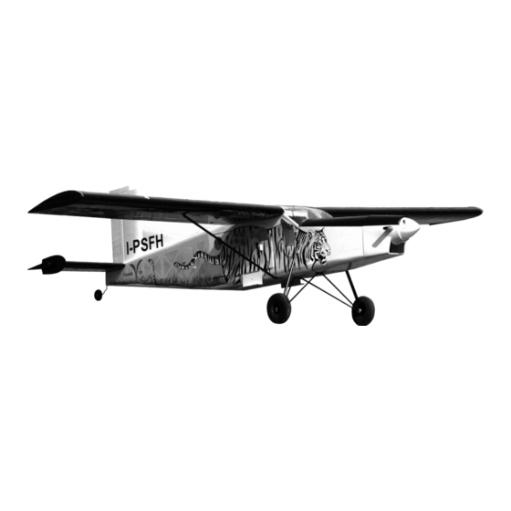
Pilatus
Porter
Semi scale model
107 in.
78.7 in.
14.4 lbs
26 ~ 30cc
6 Channel / 8 servos
2.720mm
2.000mm
6.500g
26 ~ 30cc
6 Kanal / 8 Servos
PC-6
"Skydive Marche"
VQA057
AUSTRALIA ARMY
VQA0571
Werbung

Verwandte Anleitungen für VQ Model Pilatus Porter PC-6

Inhaltszusammenfassung für VQ Model Pilatus Porter PC-6
- Seite 1 PC-6 Pilatus 26 ~ 30cc Porter Gas Engine Semi scale model RADIO CONTROL MODEL / RC FLUGMODELL BUILDING INSTRUCTIONS / MONTAGEANLEITUNG “Skydive Marche” VQA057 AUSTRALIA ARMY VQA0571 SPECIFICATIONS Wingspan 107 in. Length 78.7 in. Flying weight 14.4 lbs Gas Engine 26 ~ 30cc Radio 6 Channel / 8 servos...
-
Seite 2: Required For Operation (Purchase Separately) Benotigte Komponenten Fur Den Abflug (Nicht Enthalten)
REQUIRED FOR OPERATION (Purchase separately) BENOTIGTE KOMPONENTEN FUR DEN ABFLUG (Nicht enthalten) Extension for aileron servo, Flap servo. Gas Engine: 26 ~ 30cc Minimum 6 channel radio Nylon tube for airplane with 8 servos .Motor control x1 .Aileron x2 .Elevator x2 .Rudder x1 .Flap x 2 GLUE (Purchase separately) - Seite 3 1- Landing gear / Fahrwerk 5.5mm Collar Stellring 3x12mm screw Stopper (metal) 5.5mm Collar Stopper (metal) ....8 ...2 ...4 Nylon strap 5mm landing Collar Kunststoffstreifen 3mm set screw gear ....4 ....4 Aluminum tube 5mm landing gear 5mm Main landing gear (front) Caution: All holes on the bottom of the fuselage are pre-drilled at factory...
- Seite 4 2.5mm collar BOTTOM - VIEW / Unteransicht 4- Tail gear / Heckspornrad Tail gear control arm 3x12mm screw ...4 ..1 2.5mm Tail gear 2.5mm Collar ..3 2.5mm collar 2.5mm collar 3x12mm screw BOTTOM - VIEW / Unteransicht 5- Tail gear / Heckspornrad Note: Slide the tail gear push rod in to 3x12mm screw Tail gear control arm...
- Seite 5 7- Vertical Stabilizer TOP VIEW / Draufsicht Seitenleiwerk See Step 10 (installing the elevator) on next page. BOTTOM - VIEW / Unteransicht 8- Tail gear / Heckspornrad Tail gear push rod 2x350mm rod ..2 Bottom View 9- Horizontal Stabilizer TOP VIEW / Draufsicht Hohenleitwerk 6x22mm dowel ..2...
- Seite 6 TOP VIEW / Draufsicht 10- Horizontal Stabilizer Hohenleitwerk 5 minute epoxy ! Securely glue together. If coming off during flight, you lose control of your air plane. Apply a thin layer of machine oil or petroleum jelly to only the pivot point of the hinges Petroleum jelly on the elevator, then push the elevator and its hinges into the hinge slots in the trailing edge of the horizontal stabilizer.
- Seite 7 Open the rear door (on the 12- Servo right side of the fuselage only) Install the servos as show Elevator servo (R) To right elevator control horn Magnetic piece To left elevator control horn Elevator servo (L) OPEN To ruder control horn Rudder servo SIDE-VIEW / Seitenansicht 13- Engine - Cowl / Motor - Motorhaube...
- Seite 8 14A- Li-Po Battery stand 3x12mm screw .....3 Li-Po battery stand (3mm plywood) Put the Li-Po battery in place. Magnetic battery hatch. Install the Li-Po battery stand and secure it in place using three 3x12mm screws Note: Three holes on the battery stand pre-drilled at factory Install the magnetic battery hatch.
- Seite 9 Cut away only the cover 16- Decor / Aufkleber Plywood Plywood Plywood Plastic Plywood (x2) Plywood (x2) 17- Decor / Aufkleber 18- Installing the wing / Tragflacheneinbau Aluminum tube...
- Seite 10 19- Servo installation / Servoeinbau Flap servo Servo mount 5/64(2x10mm) screw Flap servo hatch WING BOTTOM Aileron servo 5/64(2x10mm) Servo mount screw Aileron servo hatch Aileron servo WING BOTTOM extension cord BOTTOM - VIEW / Unteransicht 20- Linkages / Anlenkungen Aileron servo / Querruder servo Control horn 2x30mm screw...
- Seite 11 21- Installing the wing / Tragflacheneinbau Wooden dowel Wooden dowel 22- Installing the wing / Tragflacheneinbau 5x20mm screw 5mm washer ..2 ....2 23- Installing the wing Tragflacheneinbau 3x15mm screw / Schraube ......2 Wing 3x15mm sscrew Wing brace The holes on the bottom of the wings and bottom of the fuselage are pre-drilled at factory All blindnuts are...
- Seite 12 Aileron 24- Balance / Schwerpunkt 15mm 15mm 30mm Querruderausschlag Rudder Flap 30mm Seitenruderausschlag 20mm Do not try to fly an out-of balance model! Uberprufen Sie vor dem Flug den Schwerpunkt. 15mm Elevator 90 ~ 95mm 15mm Hohenruderausschlag 25- Door 4mm nylon bolt ....2 Secure the door (left and right side) using the 4x25mm nylon bolt as show.