
Verwandte Anleitungen für EPS PSI 880-170R


Inhaltszusammenfassung für EPS PSI 880-170R
- Seite 1 Netzgeräte Serie Power Supply Series PSI 800 R 5000W PSI 880-170R : 21 540 411 PSI 8200-70R : 21 540 413 PSI 8500-30R : 21 540 412...
- Seite 3 Impressum Sicherheitshinweise EPS Stromversorgung GmbH Alter Postweg 101 Der Querschnitt der Lastanschlußkabel muß für den • 86159 Augsburg maximalen Ausgangsstrom des jeweiligen Gerätes Germany ausgelegt sein! Telefon: 0821 / 570451-0 Es ist sicherzustellen, daß keine Gegenstände in • Web: www.eps-germany.de die Lüftungsöffnungen gelangen!
-
Seite 4: Inhaltsverzeichnis
Inhaltsverzeichnis Seite 1. Allgemeines ................................5 1.1 Einleitung ................................5 1.2 Sichtprüfung ................................. 5 1.3 Lieferumfang ................................ 5 2. Installation .................................. 5 2.1 Montage ................................5 2.2 Netzanschluß ............................... 5 2.3 DC-Anschluß ................................ 5 3. Funktionsbeschreibung .............................. 6 3.1 Allgemein ................................6 3.2 Fernfühlung (Remote sense) .......................... -
Seite 5: Allgemeines
Beschreibung Allgemeines Installation 1.1 Einleitung 2.1 Montage Das microcontrollergesteuerte Einbaunetzgerät der Das Gerät ist für die senkrechte Wandmontage kon- Serie PSI 800 R ist sowohl für den Festspannungs- zipiert und so zu plazieren, daß ein ungehinderter betrieb im normalen Industrieeinsatz als auch für Luftstrom für die Lüfterkühlung gewährleistet ist. -
Seite 6: Funktionsbeschreibung
Beschreibung Funktionsbeschreibung 3.4 Übertemperaturabschaltung (OT) Die Geräte sind mit einer internen Temperaturüber- 3.1 Allgemein wachung ausgestattet. Das Netzgerät ist auf 0V Ausgangsspannung und Wird eine bestimmte Innentemperatur überschritten, 100% Ausgangsstrom voreingestellt. Die Ausgangs- führt dieses zur Abschaltung des Ausganges und zu leistung von 5000W ist nicht einstellbar, wird jedoch einer Alarmmeldung. -
Seite 7: Konfigurierbare Spannungsprofile
Beschreibung 3.8 Bedienorte Dieser Alarm wird auch über den Ausgang „ERROR“ der analogen Schnittstelle signalisiert. Erst nach dem Bedienorte sind die Zugriffsmöglichkeiten auf das Quittieren des Alarms kann der Leistungsausgang Gerät. Bei dieser Serie gibt es mehrere Bedienorte, wieder eingeschaltet werden. die dem Anwender durch einen Statustext in der An- zeige mitgeteilt werden: 3.7... -
Seite 8: Technische Daten
Beschreibung 3.9 Technische Daten PSI 880-170 R PSI 8200-70 R PSI 8500-30 R Netzeingang Eingangsspannungsbereich 340…460V 340…460V 340…460V Benötigte Phasen L1, L2, PE L1, L2, PE L1, L2, PE Eingangsfrequenz 50/60Hz 50/60Hz 50/60Hz Eingangssicherung 2x T16A 2x T16A 2x T16A Eingangsstrom max. 16A max. 16A max. 16A Leistungsfaktor >... -
Seite 9: Ansichten
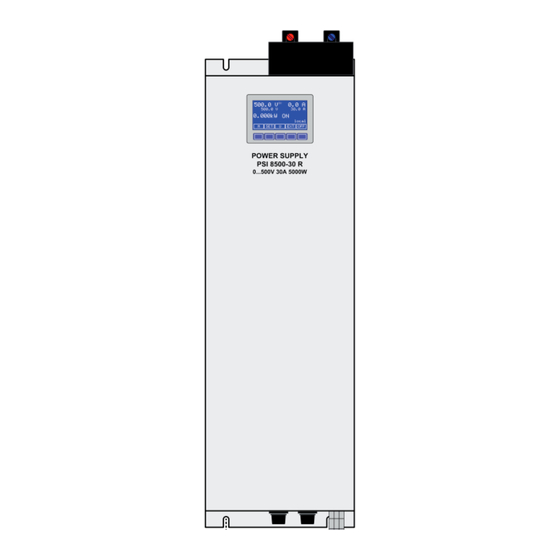
Beschreibung 3.10 Ansichten Bild 1 zeigt das 500V-Modell mit passender Abdek- kung der DC-Ausgangsklemme. Bei den anderen Modellen werden andere DC-Ausgangsklemmen verwendet, deren Abdeckung geringere Maße hat. Für die Mindesteinbauhöhe siehe „3.9 Technische Daten“. Bild 1. Vorderseite Bedienungsanleitung Stand: 13.05.2011 PSI 800 R Serie... - Seite 10 Beschreibung Vorderseite Bild 2. Oberseite Vorderseite © 2006, Elektro-Automatik GmbH & Co. KG Irrtümer und Änderungen vorbehalten Bild 3. Unterseite Bedienungsanleitung Stand: 13.05.2011 PSI 800 R Serie...
-
Seite 11: Bedienung Des Gerätes
Bedienung des Gerätes Bedienung 4.1 Bedien- und Anzeigeeinheit 4.1.1 Aufteilung der Betriebsanzeige Der Zustand des Leistungsausgangs, Meldungen (Alarme, Warnungen) und der Bedienort (siehe Ab- Die Anzeige teilt sich auf in Bereiche für die Ausgangs- schnitt 3.8) werden im rechten unteren Bereich des werte, die Sollwerte, den Zustand des Leistungsaus- Displays angezeigt. -
Seite 12: Auswahl Der Parameter
Bedienung des Gerätes 4.4 Direktes Einstellen der Sollspannung Alle anderen Spannungsprofile können nur in einem bestimmten Bereich verändert werden (siehe Tabel- Aus der Betriebsanzeige heraus kann der Span- len auf Seite 7). Über die Tasten wird das nungssollwert eingestellt werden, ohne das momen- gewünschte Spannungsprofil markiert. -
Seite 13: Menüpunkt „Analogue Interface
Bedienung des Gerätes Zustand nach einer Übertemperaturabschaltung 4.5.2 Menüpunkt „Analogue interface“ Hier werden Einstellungen zur eingebauten, analogen OT disappear (Voreinstellung: auto Schnittstelle getroffen. Sollte nach einer Übertemperaturabschaltung eine Die analogen Eingänge und Ausgänge der Sollwerte, automatische Wiedereinschaltung des Leistungsaus- Istwerte und Referenzspannung können sowohl im gangs gewünscht sein, muss die Einstellung auf auto Bereich 0..5V als auch 0..10V für je 0...100% Nenn- stehen. -
Seite 14: Menüpunkt „Communication
Bedienung des Gerätes 4.6 Alarme Digital inputs (Voreinstellung: LOW) Die digitalen Eingänge und Ausgänge können sowohl Das Gerät zeigt verschiedene Alarme durch das als low-aktives Signal als auch als high-aktives Signal Symbol zusammen mit einem Kürzel an, und als arbeiten. Ein auf eingestellter Eingang löst die Signal „ERROR“... -
Seite 15: Beispiele Zur Analogen Schnittstelle
Bedienung des Gerätes Es müssen beide Sollwerte für Strom und Spannung An den analogen Ausgängen VMON und CMON vorgegeben werden. Bei Bedarf kann einer der Soll- werden die aktuellen Werte für Spannung und Strom werte zu Pin VREF gebrückt werden und gibt dann in einem Spannungsbereich von 0..10V bzw. -
Seite 16: Pinbelegung Und Technische Daten Der Analogen Schnittstelle
Bedienung des Gerätes 5.2.2 Pinbelegung und technische Daten der analogen Schnittstelle Name Bezeichnung Pegel Elektrische Eigenschaften 0….10V entspricht 0….100% U Genauigkeit < 0.2%, U = 12V VSEL AI Sollwert Spannung Nenn 0….10V entspricht 0….100% I CSEL AI Sollwert Strom Eingangsimpendanz >100k Nenn Genauigkeit < 0.1% bei I = 10mA VREF AO Referenzspannung... -
Seite 17: Sonstiges
Bedienung des Gerätes 7.2 Firmwareaktualisierung Die Verdrahtung der Share-Klemme der Geräte, die im Sharebus-Betrieb arbeiten sollen, ist sehr simpel. Eine Firmwareaktualisierung sollte nur vorgenommen Es werden lediglich jeweils alle Plus-Pins und jeweils werden, wenn nachweislich Fehler in einer bestimm- alle Minus-Pins der Klemme „Share“ verbunden. ten Version der Firmware bestehen, die durch eine Der Leitungsquerschnitt ist hierbei nicht kritisch. - Seite 18 Bedienung des Gerätes Grafische Verdeutlichung der symmetrischen Schal- tung: Beispieldarstellung aus der Norm, Bild C.3c, Schutz- leiterstrommessung, Ersatzableitstrommeßverfahren: Hinweis: Das Bild unten zeigt das Meßverfahren für zweiphasige Netzanschlüsse. Bei einem Dreh- Netzeingang stromgerät wird Phase N dann durch L2 und/oder L3 ersetzt.
- Seite 19 About Safety instructions EPS Electronic Power Supplies Ltd. Alter Postweg 101 The cross section of the load leads has to match • 86159 Augsburg the nominal current of the device! Germany Avoid any damage to the device, do not insert metal •...
- Seite 20 Table of contents Page 1. General ..................................21 1.1 Introduction ................................ 21 1.2 Visual check ............................... 21 1.3 Scope of delivery ..............................21 2. Installation ................................21 2.1 Mounting ................................21 2.2 Input connection ..............................21 2.3 DC output connection ............................21 3.
-
Seite 21: General
About the device General Installation 1.1 Introduction 2.1 Mounting The microprocessor controlled power supply of the The device is designed for vertical wall mount. It is PSI 800 R series are designed for wall mount and required to mount it in a way that allows unimpeded work with fan cooling. -
Seite 22: Functional Description
About the device Functional description 3.5 Output restoration after mains blackout After a mains blackout, which is considered the same 3.1 General as switching the input voltage off by hand, the device The power supply is pre-configured to 0V output and will reconstruct the last condition by restoring output 100% output current. -
Seite 23: About The Device
About the device 3.7 Configurable voltage profiles 3.8 Control locations The device features several voltage profiles that are Control locations are places from where the device is pre-configured for common applications. The first accessed. With this series, there are several control profile allows to set voltage and current within the locations which are indicated by status texts in the full nominal values, i.e. -
Seite 24: Technical Specifications
About the device 3.9 Technical specifications PSI 880-170 R PSI 8200-70 R PSI 8500-30 R Mains input Input voltage range 340…460V 340…460V 340…460V Required phases L1, L2, PE L1, L2, PE L1, L2, PE Input frequency 50/60Hz 50/60Hz 50/60Hz Input fuse 2x T16A 2x T16A 2x T16A Input current max. -
Seite 25: Views
About the device 3.10 Views Figure 1 shows the 500V model with its DC output cover. Other models will slightly differ regarding the DC output and the cover. This effects the installation dimensions. See section „3.9 Techni- cal specifications“ for details about the minimum installation dimensions. - Seite 26 About the device Front Figure 2. Top side Front © 2006, Elektro-Automatik GmbH & Co. KG Irrtümer und Änderungen vorbehalten Figure 3. Bottom side Instruction Manual Date: 05-13-2011 PSI 800 R Series...
-
Seite 27: Handling The Device
Handling the device Operation 4.1 Control and display panel 4.2 Selecting a voltage profile 4.1.1 Layout of the display The display is seperated into areas for set values, Note: Switching voltage profiles is only possible during actual values, the output state, device status and the output = off. current button assignments. The voltage profile selection menu is accessed by the The button assigment field changes interactively button... -
Seite 28: Selecting Parameters
Handling the device 4.4 Direct voltage adjustment If button is pushed instead, the selected profile is opened for adjustment. In the main screen the output voltage can also be directly accessed for adjustment by the button. 4.2.1 Selecting parameters It selects the voltage set value for adjustment. The parameter that is going to be adjusted is selected Adjustment and submission or cancellation of the by the... -
Seite 29: Menu Item „Analogue Interface
Handling the device Display illumination 4.5.2 Menu item „Analogue interface“ This configures the built-in analogue interface. The Backlight (Default: Delay 60s) analogue inputs and outputs can work with the com- is set, the backlight is gene- Backlight = Delay 60s mon 0...5V and 0...10V control voltage ranges. In the rally off and will be switched on for 60s after every range 0...5V the resolution and accuracy are halved. -
Seite 30: Menu Item „Communication
Handling the device Digital inputs (Default: LOW) The only exception is the OT alarm, where the output can automatically switch on again after the device has The digital inputs can be selected to be low-active or cooled down, if in menu „General settings“... -
Seite 31: Pin Assignment And Technical Specs Of The Analogue Interface
Handling the device 5.2.1 Pin assignment and technical specs of the analogue interface Name Description Level Electrical specifications 0….10V correspond to Accuracy 0.2%, U = 12V VSEL Set value: voltage 0….100% U 0….10V correspond to CSEL Set value: current Input impendance >100k 0….100% I Accuracy < 0.1% bei I = 10mA VREF AO Reference voltage... -
Seite 32: Other Applications
Handling the device Other applications Set values 1 Analogue inputs (AI) 6.1 Series connection It is possible to connect multiple units of the same type to a series connection if these rules are followed: No master-slave operation • The grounds of the analogue interfaces MUST •... -
Seite 33: Miscellaneous
Miscellaneous 7.1 Accessories and options Following accessories are optionally available: a) Digital interface cards Pluggable and retrofitable, digital interface cards for USB, RS232, CAN or Ethernet/LAN (SCPI only) are available. There is one interface card slot available with every model. Following options are available: a) Watercooling Internally integrated water cooling block.