Equip 4-Port USB 2.0 Sharing Switch Bedienungsanleitung
Verfügbare Sprachen
Verfügbare Sprachen
Inhaltsverzeichnis

Verwandte Anleitungen für Equip 4-Port USB 2.0 Sharing Switch


Inhaltszusammenfassung für Equip 4-Port USB 2.0 Sharing Switch
- Seite 1 4-Port USB 2.0 SHARING SWITCH 128544...
-
Seite 6: Verpackungsinhalt
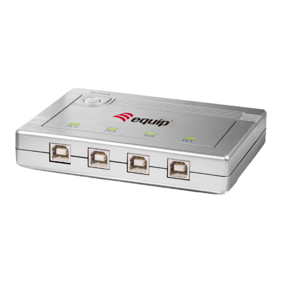
1. Einführung Danke für den Kauf des equip™ 4-Port USB 2.0 Sharing Switch. Der intelligente USB Sharing Switch ermöglicht 4 Computern einen USB-Drucker oder ein USB 2.0 Gerät gemeinsam zu benutzen. Es können Ihre Kosten, Zeit, Raum, Energie zu sparen, und Ausrüstung, um die Effizienz zu verbessern. -
Seite 7: Anwendungsdiagramm
2. Anwendungsdiagramm 3. Kabeldiagramm USB A-B kabel: 4. Technische Spezifikationen Modell Nr. 128544 4 x USB Type B Buchse Anschlusstyp 1 x USB Type A Buchse Drucktaste (PC/MAC/SUN) USB-Geräteauswahl Hot Key (PC) PC-Anschluss-LED Kabellänge (meter) 1,80 USB-Energie Bus-Strom 0~50℃ Betriebstemperatur -20~60℃... -
Seite 8: Led-Anzeige
5. LED Anzeige Auf der Geräteoberseite gibt es zwei PC-LEDs: Wenn einer der PC-Ports an den USB-Port angeschlossen ist, leuchtet die PC- Port-LED auf. Es leuchtet jeweils nur eine PC-Port-LED auf. Wenn die PC-LED blinkt, wird eine USB-Geräteemulation oder USB- Hostaufzählung ausgeführt oder der andere PC wechselt in den Schlafmodus. - Seite 9 7. Hardwareinstallation Stellen Sie vor der Installation sicher, dass alle Peripheriegeräte und Computer ausgeschaltet sind. Verbinden Sie den Type B Anschluss des USB A/B-Kabels mit dem PC-Port des Switches und Type A Anschluss des Kabels mit dem PC. Verbinden Sie den Type A Anschluss des USB-Kabels des jeweiligen anzuschließenden Geräts mit dem USB-Port des Switches.