Werbung
Quicklinks
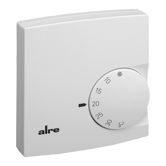
FTR 101.2xx
24 V~ Raumtemperaturregler Bimetall Unterputz im Flächenschalterrahmen
24 V~ Bimetal room temperature controller for flush installation in a flush mounted switch frame
Régulateur de température ambiante 24V~ avec capteur à bilame –
Биметаллический регулятор температуры помещения 24 V~ для скрытого монтажа в рамке для
Sicherheitshinweis!
Dieses Gerät darf nur durch eine Elektrofachkraft geöffnet und gemäß dem entsprechenden
Schaltbild im Gehäusedeckel / auf dem Gehäuse / in der Bedienungsanleitung installiert
werden. Dabei sind die bestehenden Sicherheitsvorschriften zu beachten. Nach der Instal-
lation ist der Betreiber, durch die ausführende Installationsfirma, in die Funktion und Bedie-
nung der Regelung einzuweisen. Die Bedienungsanleitung muss für Bedien- und Wartungs-
personal an frei zugänglicher Stelle aufbewahrt werden.
1. Anwendung
Dieser Raumtemperaturregler wurde speziell für die Regelung oder Überwachung von Tem-
peraturen in Büros, Wohnräumen und Hotels entwickelt. Elektrische Fußbodenheizungen
müssen über ein zusätzliches Leistungsschütz angesteuert werden. Hierbei ist darauf zu
achten, dass die Leistung der Heizung auch bei Dauerbetrieb den Estrich nicht überhitzen
kann. Bei Warmwasserheizungen oder Wasserkühlung sind maximal 5 stromlos geschlos-
sene Ventile zu verwenden.
Achtung! Bei dem speziell für 2-Rohr-Klimasysteme entwickelten Reglertyp FTR 101.265,
ist die Bedruckung des Heiz-/Kühl-Umschalters auf stromlos geschlossene Ventile ausge-
legt.
Gegebenenfalls benötigte Temperaturbegrenzungen müssen zusätzlich installiert werden.
Für andere, vom Hersteller nicht vorherzusehende Einsatzgebiete, sind die dort gültigen
Sicherheitsvorschriften zu beachten. Eignung hierfür siehe Punkt 7. Gewährleistung.
2. Funktionen
Der Raumtemperaturregler erfasst mit einem innenliegenden Bimetallfühler die Raumtem-
peratur und regelt entsprechend dem eingestellten Sollwert. Die einzelnen Reglertypen un-
terscheiden sich durch die Ausstattung, wie Schalter „Ein / Aus" und Lampe rot „Heizen"
(Typ .062), Schalter und Lampe rot „Ein / Aus" (Typ .073), Schalter „Heizen/Kühlen" (Typ
.065) sowie Schalter „Absenken/Komfort/Automatik" und Lampe grün „Nachtabsenkung"
(Typ .075)
2.1 Thermische Rückführung
Da während des Heiz- oder Kühlvorgangs der Regler die Raumtemperatur erst relativ spät
erfasst, wird mittels einer thermischen Rückführung der Regler rechtzeitig zum Ausschalten
angeregt und so eine sehr genaue Schaltdifferenz erreicht.
2.2 Bereichseinengung
Mittels der sich unter dem Knopf befindlichen Einstellfahnen kann der Einstellbereich me-
chanisch begrenzt werden. (siehe Punkt 3.).
2.3 ECO-Betrieb (Nachtabsenkung)
Bei Reglern mit ECO-Betrieb (Uhrensymbol im Anschluss-Schaltbild) wird bei Beschalten
der Klemme
mit 24 V~/4 auf eine um ca. 4 K geringere Temperatur geregelt.
3. Installation / Montage
Je nach Gerätetyp oder Verpackungsgröße, wird das Gerät entweder geschlossen oder der
schnelleren Montage wegen geöffnet ausgeliefert. Für die Befestigungsschraube ist je nach
verwendeter Schraube ein PZ 1 bzw. T7 Schraubendreher zu verwenden. Das Gerät mit
dem 50 x 50 mm Gehäusedeckel ist mittels Zwischenrahmen der Schalterhersteller nach
DIN 49075 in nahezu alle Schalterprogramme integrierbar. Das Gerät mit dem 55 x 55 mm
Gehäusedeckel ist ebenfalls für diverse Schalterprogramme geeignet. Bei Mehrfachrahmen
ist der Regler immer an unterster Stelle zu montieren. Der Regler ist zur Montage in die
UP-Dose bestimmt und darf nicht direkt Wärme- oder Kältequellen ausgesetzt werden. Es
ist darauf zu achten, dass der Regler auch rückseitig keiner Fremderwärmung oder -küh-
lung, z.B. bei Hohlwänden durch Zugluft oder Steigleitungen ausgesetzt wird.
Zum Öffnen des Reglers ist die Schraube nach Abziehen des Einstellknopfes zu lösen und
die Reglerkappe inklusive Rahmen abzunehmen. Nach elektrischem Anschluss und Mon-
tage in die UP-Dose, ist der Regler in umgekehrter Reihenfolge wieder zu schließen.
Regler 50 x 50 mit Standard-Rahmen
Controller (50 x 50) with standard type frame
Stand 4.2013 (13/021)
pour l'installation encastrée dans un cadre de recouvrement plat
поверхностного выключателя
Regler 50 x 50 mit Beispiel-Rahmen und Zwischenrahmen
Controller (50 x 50) with sample frame and intermediate frame
D
Safety information!
Expert electricians only may open this device in due compliance with the wiring diagram
shown in the housing cover / on the housing / represented in the corresponding operating
instructions. All expert electricians charged with the execution of such works must comply
with the relevant safety regulations currently operative and in force. The company charged
with the installation of the device must, after the completion of the installation works,
instruct the user of the control system into its functions and in how to operate it correctly.
These operating instructions must be kept at a place that can be accessed freely by the
operating and/or servicing personnel in charge.
1. Application
This room temperature controller has been specially devised for the control and super vision
of temperatures in offices, living spaces and hotels. For the triggering of electric floor hea-
ting systems a power contactor is needed in addition. Regarding floor heating systems,
care must be taken to ensure that the performance of the controlled system cannot, even
if the system is operated continuously, result in an overheating of the pavement. With hot-
water heating systems, no more than 5 normally closed valves must be used.
Caution: The controller model FTR 101.265 has been specially developed for the control
of two-pipe climate systems. The imprint on its heating/cooling changeover switch relates
to normally closed valves only. Where applicable, temperature limiters need to be installed
in addition. Regarding other applications not to be foreseen by the manufacturer of this
device, the safety standards these applications need to be followed and adhered to. Regar-
ding the aptitude of the device for any such application, please refer to section 7. herein.
2. Functional description
The room temperature controller described herein is equipped with an internal bimetal sensor
that captures the currently existing room temperature. The device controls the related heating
or cooling system in accordance with the adjusted set value. The individual controller models
differ by the different components they are endued with, such as "ON/OFF" switches, red
lamps for heating mode indication (type version .062), switches with red "ON/OFF" indicator
lamp (type version .073), "heating/cooling" mode changeover switches (type version .065),
"temperature decrease / comfort mode / automatic mode" selector switches and green "night
temperature decrease mode" indicator lamps (type version .075).
2.1 Thermal recirculation
As, during the heating or cooling procedure, the controller usually captures the actually pre-
vailing room temperature at a rather late point, a thermal recirculation has been realised with
the device that enables to excite it early enough with the consequence that a very precise
switching difference can be attained.
2.2 Suppression of the setting range
The setting elements (pins) located underneath of the knob enable to delimit the setting
range mechanically (see section 3.).
2.3 ECO mode (night temperature decrease mode)
With all controller models that enable to operate in ECO mode (indicated by the clock symbol
shown in the connection diagram), the room temperature is decreased by approx. 4K when
connecting the 24 V~/4 power supply to the terminal
3. Mounting / Installation
The device is, depending on the type version of the device or size of the package used for it,
either delivered in closed or, in order to facilitate its fast installation, also in opened conditi-
on. The device with the 50x 50 mm housing cover can be integrated into almost all currently
available flush switch installation frame systems when using DIN 49075 compliant inter-
mediate frames. The device with the 50 x 50 mm housing cover is likewise suited for use
with different commercially available switch lines. Depending on the type of screw used,
either a PZ1 or T7 screwdriver needs to be used for the fastening of the cover fixing screw.
If using multiple frames, the controller must always be mounted in the lowest position. The
controller is determined for installation on an UP box and must not be exposed to any heat
or cold sources whatsoever. Also care must be taken to ensure that it is not exposed to the
influence of heat or cold sources that warm or cool the device at its back (through air flows
in cavity walls or the temperatures radiated by ascending pipelines, f. ex.).
To open the controller, remove the adjusting knob first, then loosen the screw and remove
the controller cap. After its electrical connection and installation in the UP box, the closing
of the controller takes place in inverse order.
1
.
Regler 55 x 55 mit Beispiel-Rahmen
Controller (55 x 55) with sample frame
GB
4 12 522 03
Werbung

Verwandte Anleitungen für Alre FTR 101.2 Serie


Inhaltszusammenfassung für Alre FTR 101.2 Serie
- Seite 1 FTR 101.2xx 24 V~ Raumtemperaturregler Bimetall Unterputz im Flächenschalterrahmen 24 V~ Bimetal room temperature controller for flush installation in a flush mounted switch frame Régulateur de température ambiante 24V~ avec capteur à bilame – pour l’installation encastrée dans un cadre de recouvrement plat Биметаллический...
- Seite 2 The setting pins located underneath of the adjusting knob enable to delimit the setting ran- Um den Einstellbereich Einzuengen, wird der sich unter dem Einstellknopf befindliche Stift ge of the controller mechanically. To enable this, the adjusting knob must be removed by abgezogen und die Einstellfahnen verstellt (rot für maximal und blau für minimal mögliche pulling it off and, after the adjustment of the related pins (end stops, red for max.
- Seite 3 2. Fonctionnement 2.Функции Регулятор температуры помещения с помощью расположенного внутри биметаллического Le régulateur de température ambiante décrit dans cette notice d’instructions saisit, sur датчика регистрирует температуру в помещении и регулирует в соответствии с la base des données livrées par un détecteur bilame interne, la température existant dans настроенным...
- Seite 4 эксплуатации входит в обязанности заказчика; за это мы не несем никакой ответственности. Оставляем за собой право на изменения. ALRE-IT Regeltechnik GmbH · Richard-Tauber-Damm 10 · D-12277 Berlin Tel.: +49(0)30 /399 84-0 · Fax: +49(0)30/391 70 05 · mail@alre.de · www.alre.de...